EP1201339A2 - An apparatus for positioning a cutter of a tool relative to the spindle of a machine tool - Google Patents
An apparatus for positioning a cutter of a tool relative to the spindle of a machine tool Download PDFInfo
- Publication number
- EP1201339A2 EP1201339A2 EP01309051A EP01309051A EP1201339A2 EP 1201339 A2 EP1201339 A2 EP 1201339A2 EP 01309051 A EP01309051 A EP 01309051A EP 01309051 A EP01309051 A EP 01309051A EP 1201339 A2 EP1201339 A2 EP 1201339A2
- Authority
- EP
- European Patent Office
- Prior art keywords
- fitting
- spindle
- piston
- tool
- axis
- Prior art date
- Legal status (The legal status is an assumption and is not a legal conclusion. Google has not performed a legal analysis and makes no representation as to the accuracy of the status listed.)
- Granted
Links
Images



Classifications
-
- B—PERFORMING OPERATIONS; TRANSPORTING
- B23—MACHINE TOOLS; METAL-WORKING NOT OTHERWISE PROVIDED FOR
- B23B—TURNING; BORING
- B23B29/00—Holders for non-rotary cutting tools; Boring bars or boring heads; Accessories for tool holders
- B23B29/03—Boring heads
- B23B29/034—Boring heads with tools moving radially, e.g. for making chamfers or undercuttings
- B23B29/03432—Boring heads with tools moving radially, e.g. for making chamfers or undercuttings radially adjustable during manufacturing
-
- B—PERFORMING OPERATIONS; TRANSPORTING
- B23—MACHINE TOOLS; METAL-WORKING NOT OTHERWISE PROVIDED FOR
- B23B—TURNING; BORING
- B23B2270/00—Details of turning, boring or drilling machines, processes or tools not otherwise provided for
- B23B2270/02—Use of a particular power source
- B23B2270/025—Hydraulics
-
- Y—GENERAL TAGGING OF NEW TECHNOLOGICAL DEVELOPMENTS; GENERAL TAGGING OF CROSS-SECTIONAL TECHNOLOGIES SPANNING OVER SEVERAL SECTIONS OF THE IPC; TECHNICAL SUBJECTS COVERED BY FORMER USPC CROSS-REFERENCE ART COLLECTIONS [XRACs] AND DIGESTS
- Y10—TECHNICAL SUBJECTS COVERED BY FORMER USPC
- Y10T—TECHNICAL SUBJECTS COVERED BY FORMER US CLASSIFICATION
- Y10T408/00—Cutting by use of rotating axially moving tool
- Y10T408/83—Tool-support with means to move Tool relative to tool-support
- Y10T408/85—Tool-support with means to move Tool relative to tool-support to move radially
-
- Y—GENERAL TAGGING OF NEW TECHNOLOGICAL DEVELOPMENTS; GENERAL TAGGING OF CROSS-SECTIONAL TECHNOLOGIES SPANNING OVER SEVERAL SECTIONS OF THE IPC; TECHNICAL SUBJECTS COVERED BY FORMER USPC CROSS-REFERENCE ART COLLECTIONS [XRACs] AND DIGESTS
- Y10—TECHNICAL SUBJECTS COVERED BY FORMER USPC
- Y10T—TECHNICAL SUBJECTS COVERED BY FORMER US CLASSIFICATION
- Y10T408/00—Cutting by use of rotating axially moving tool
- Y10T408/89—Tool or Tool with support
- Y10T408/905—Having stepped cutting edges
- Y10T408/906—Axially spaced
-
- Y—GENERAL TAGGING OF NEW TECHNOLOGICAL DEVELOPMENTS; GENERAL TAGGING OF CROSS-SECTIONAL TECHNOLOGIES SPANNING OVER SEVERAL SECTIONS OF THE IPC; TECHNICAL SUBJECTS COVERED BY FORMER USPC CROSS-REFERENCE ART COLLECTIONS [XRACs] AND DIGESTS
- Y10—TECHNICAL SUBJECTS COVERED BY FORMER USPC
- Y10T—TECHNICAL SUBJECTS COVERED BY FORMER US CLASSIFICATION
- Y10T409/00—Gear cutting, milling, or planing
- Y10T409/30—Milling
- Y10T409/30448—Milling with detachable or auxiliary cutter support to convert cutting action
-
- Y—GENERAL TAGGING OF NEW TECHNOLOGICAL DEVELOPMENTS; GENERAL TAGGING OF CROSS-SECTIONAL TECHNOLOGIES SPANNING OVER SEVERAL SECTIONS OF THE IPC; TECHNICAL SUBJECTS COVERED BY FORMER USPC CROSS-REFERENCE ART COLLECTIONS [XRACs] AND DIGESTS
- Y10—TECHNICAL SUBJECTS COVERED BY FORMER USPC
- Y10T—TECHNICAL SUBJECTS COVERED BY FORMER US CLASSIFICATION
- Y10T409/00—Gear cutting, milling, or planing
- Y10T409/30—Milling
- Y10T409/309296—Detachable or repositionable tool head
Definitions
- the invention relates to an apparatus for positioning a cutter of a tool, which is adapted to be mounted to a spindle or a spindle apparatus of a machine tool, relative to the spindle.
- JPP '735 Japanese Unexamined Patent Publication (Kokai) No. 10-286735 (JPP '735) describes an attachment tool having an inclined shaft rotationally supported in a housing.
- the housing is adapted to be detachably secured to the spindle head of a machine tool with a tapered ring clamped therebetween.
- a position adjusting means is provided for adjusting and fixing the position of the tapered ring in the axial direction of the main spindle of the machine tool so that the tapered ring is resiliently deformed to increase its diameter. This absorbs looseness between the housing of the attachment tool and the spindle head.
- the position adjusting means described in JPP '735 positions the tapered ring itself and does not position the cutter itself, in particular the tip of the cutter relative to the axis of the spindle of the machine tool.
- the attachment tool of JPP '735 reduces or removes the looseness between the attachment tool and the spindle head, it cannot position the cutter tip accurately relative to the spindle of the machine tool.
- the invention is directed to solve the prior art problems, and to provide an improved apparatus for positioning the cutter tip of a tool relative to the spindle of a machine tool.
- the objective of the invention is to provide an apparatus for positioning the cutter tip of a tool which includes a movable cutter.
- the objective of the invention is to provide an apparatus for positioning the cutter tip of a tool which includes input and output shafts rotatably supported in a housing which is mounted to a housing of a spindle device of a machine too and a cutter mounted to the output shaft.
- an apparatus for positioning a cutter of a tool relative to a spindle of a machine tool which includes a spindle having a rotating axis and a spindle housing for supporting the spindle for rotation about the rotating axis, the apparatus comprising:
- an apparatus for positioning a cutter of a tool relative to a spindle of a machine tool which includes a spindle having a rotating axis and a spindle housing for supporting the spindle for rotation about the rotating axis, the apparatus comprising:
- a tool 10 is a boring bar with a movable cutter.
- the tool 10 has a shank 12 provided with a hollow tapered portion 12a at the rear or proximal end thereof.
- the tapered portion 12a is adapted to be fitted into a tapered hole S a of a spindle S of a machining center (not shown).
- the shank 12 has a central axis O which is aligned with the rotational axis of the spindle S when the tool 10 is mounted to the spindle S.
- a coolant inlet portion 14 extends along the central axis O.
- the coolant inlet portion 14 is fitted into a coolant passage (not shown) provided through the spindle S, when the tool 10 is mounted to the spindle S, to receive a coolant from a coolant supply source (not shown) provided outside of the machining center through the coolant passage.
- a cylinder bore 12b Adjacent to the distal end of the shank 12, a cylinder bore 12b is formed along an axis O 1 perpendicular to the central axis O. The opening of the cylinder bore 12b is closed by a closure 20.
- a piston 16 is provided in the cylinder bore 12b slidable in the direction of the axis O 1 .
- a fluid chamber 18 is defined between the cylinder bore 12b and the piston 16. The fluid chamber 18 is fluidly connected to the coolant inlet portion 14 through a coolant supply passage 12c provided in the shank 12.
- a rough-machining cutter 30 is detachably secured to the exterior side surface of the shank 12.
- the piston 16 has an arm portion 16a extending along the axis O 1 to the outside through a central opening provided in the closure 20. At the end of the arm portion 16a, a finishing cutter 26a is detachably secured by a cutter block 26.
- the piston 16 is axially inwardly biased to the direction away from the closure 20 by a spring 28 provided around the arm portion 16a.
- Positioning means 22 and 24 composed of male and female members is provided between the closure 20 and the piston 16. In particular, the male member 22 is connected to the closure 20 and the female member 24 is connected to the piston 16.
- the male member 22 of the positioning means has an annular base member 22a including a central opening 22d for the passage of the arm portion 16a, a plurality of fitting protrusions 22b and abutments 22c defined on the base member 22a.
- the fitting protrusions 22b and the abutments 22c are formed to axially extend (in the direction of the axis O 1 when assembled) from one end face, in particular axially inner end face when assembled, of the base member 22a and are circumferentially and alternatively disposed at an angle.
- the fitting protrusions 22b are formed into substantially a rectangular solid shape having tapered side surfaces 22e which approach each other toward the distal end of the fitting protrusion, as shown in Figure 2B, and a pair of parallel fitting surfaces 22f provided on the opposite sides of the fitting protrusions 22b.
- the end faces of the abutments 22c are disposed in a plane perpendicular to the axis of the base member 22a.
- the female member 24 of the positioning means comprises an annular base member 24a including a central opening 24d for the passage of the arm portion 16a and fitting recesses 24b and abutments 24c.
- the fitting recesses 24b and the abutments 24c are circumferentially and alternatively disposed at an angle.
- the fitting recesses 24b axially retreat (in the direction of the axis O 1 when assembled) from one end face, in particular the axially outer end face when assembled, of the base member 24a to receive the fitting protrusions 22b of the male member 22.
- a pair of fitting arms 24e are provided in each of the fitting recesses 24b, in particular on the periphery of the opening of the recess, so that the each pair of the fitting arms 24e fit on the fitting surfaces 22b of each of the fitting protrusions 22b.
- the fitting arms 24e extend in the plane of the end face of the base member 24a where the fitting recesses 24b are formed.
- Each of the abutments 24c is a protrusion in the form of a quadrant extending from the end face of the base member 24a.
- the end faces of the abutments 24c are disposed in a plane perpendicular to the axis of the base member 24a.
- the tool 10 is a boring bar which is used in a machining center and coaxially disposed relative to a bore (not shown) precedently provide in a workpiece (not shown).
- a boring process is carried out on the inner surface of the precedently provided bore with the rough-machining cutter 30 by advancing the tool 10 in the direction of the central axis O with the spindle S of the machining center rotating.
- the piston 16 is retracted by decreasing the pressure within the fluid chamber 18.
- pressurized coolant is supplied to the fluid chamber 18 from the coolant source through the coolant passage and the coolant supply passage 12c. This forces the piston 16 outwardly along the axis O 1 .
- the female member 24 of the positioning means is outwardly pressed by the piston 16 along the axis O 1 toward the male member 22 so that the male member 22 and the female member 24 finally fit to each other.
- the fitting protrusions 22b of the male member 22 move into the fitting recesses 24b of the female member 24, with the fitting arms 24e bent, until the abutments 22c and 24c of the male and female members 22 and 24 contact each other so that the distal ends of the fitting arms 24e and the fitting surfaces 24f of the fitting protrusions 22b snugly fit to each other.
- the tapered portions 22e of the fitting protrusions 22b allow the fitting protrusions 22b to be smoothly centered between the fitting arms 24e when the fitting protrusions 22b move into the respective fitting recesses 24b so that the fitting protrusions 22b is clamped by the ends of the fitting arms 24e.
- the male member 22 and the female member 24 are axially positioned relative to each other by contacting the abutments 22c and 24c of the male and the female members 22 and 24 with each other, and circumferentially positioned by the fitting arms 24e clamping the fitting protrusions 22b.
- fitting the male and female members of the positioning means 22 and 24 to each other positions the arm portion 16a of the piston 16 axially and radially relative to the axis O 1 so that the finishing cutter 26a mounted to the distal end of the arm portion 16a is precisely positioned relative to the central axis O. Therefore, the finishing cutter 26a is precisely positioned to the spindle S of the machine tool.
- finishing cutter 26a is positioned by advancing the piston 16, the inner surface of the bore in the workpiece, which inner surface has been machined by the rough-machining cutter 30, is finished with the finishing cutter 26a by moving the tool 10 rewardly with the spindle S rotating.
- the invention is described regarding to a boring bar with a cutter movable along the axis different from the rotational axis of the spindle.
- the invention can be applied to a boring bar which includes a cutter movable along the rotational axis of the spindle S.
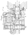
- a tool 50 is so-called a attachment tool or a spindle attachment which is adapted to be mounted to the end of a spindle apparatus of a machining center.
- the spindle apparatus includes a spindle S which is rotationally supported by a housing S h (hereinafter, the spindle housing S h ) of the spindle apparatus.
- the spindle S includes a tapered hole S a for receiving an input shaft 54 of the tool 50 at the end of the spindle S.
- An end plate E is mounted to the spindle housing S h around the end portion of the spindle S.
- a female member 64 of positioning means similar to the female member 24 of the first embodiment, is integrally connected to the end plate E.
- fitting protrusion 64 is shown as a portion of the male member.
- the female member 64 has an annular base member 64a, integrally connected to the end plate E, which female member includes a central opening 64d for the passage of the spindle S, a plurality of fitting recess 64b and abutments 64c which are circumferentially alternatively disposed on one end face, in particular axially outer end face when assembled, of the base member 64a.
- the fitting recesses 64b axially retreat (in the direction of the central axis O) from the one end face of the base member 64a to receive fitting protrusions 62 of the male member connected to the spindle housing.
- a pair of fitting arms 64e are provided on the periphery of the opening of each of the fitting recesses 64b, as in the first embodiment, so that the each pair of the fitting arms 64e fit on the fitting surfaces (not shown) of each of the fitting protrusions 62.
- the fitting arms 64e extend substantially in the plane of the end face of the base member 64a where the fitting recesses 64b are formed.
- Each of the abutments 64c is a protrusion in the form of a substantially a rectangular solid shape having end faces disposed in a plane perpendicular to the axis of the base member 64a.
- the tool 50 includes an input shaft 54 having a central axis O which is aligned with the rotational axis of the spindle S when the tool 50 is mounted to the spindle S.
- the tool 50 further includes an intermediate shaft 56 parallel to the input shaft 54 and an output shaft 58 extending along an axis O 2 perpendicular to the central axis O.
- the shafts 54, 56 and 58 are rotationally supported in a tool housing 52.
- a tapered portion 54a which is adapted to be fitted into the tapered hole S a of the spindle S, is provided at the rear end of the input shaft 54.
- the tapered portion 54a is drawn in the reward direction of the spindle S by a tool drawing device (not shown), provided in the spindle S, so that the tool 50 is securely mounted to the distal end of the spindle S.
- a gear wheel 60 is mounted to the input shaft 54 to rotate with the input shaft 54.
- a gear wheel 63 which engages the gear wheel 60 of the input shaft 54, and a helical gear wheel 68 are is mounted to the intermediate shaft 56 to rotate therewith.
- a helical gear wheel 70 which engages the helical gear wheel 68 of the intermediate shaft 56, is mounted to the output shaft 58 to rotate therewith.
- a pair of parallel cutters 74 which are oriented perpendicular to the axis O 2 , are mounted to the end of the output shaft 58.
- the positioning means which includes male and female members, which provide first and second fitting members, similar to the positioning means described with referring to Figures 2 and 3.
- the female member 64 shown in Figures 5A and 5B is connected to the end plate E of the spindle housing S h .
- a male member similar to the male member 22 shown in Figure 2, includes an annular base member which is integrally connected to the tool housing 52 and includes a central opening for the passage of the input shaft.
- a plurality of fitting protrusion 62 which is adapted to fit into the fitting recess 64b, and abutments (not shown), which adapted to contact abutments 64c of the female member 64 in direction of the central axis O, are provided on the axially outer end face of the annular base member connected to the tool housing 52 which contacts the end plate E of spindle housing S h .
- the tool 50 is mounted to the end of the spindle S with the tapered portion 54a of the input shaft 54 fitting into the tapered hole S a of the spindle S. Once the tool 50 is mounted to the spindle S, the rotation of spindle S rotationally drives the input shaft 54. The rotational power of the spindle S is transmitted to the output shaft 58 from the input shaft 54 through the gear train of the gear wheel 60 of the input shaft 54, the gear wheel 63 of the intermediate shaft 56 and the helical gear wheels 68 and 70.
- a Belleville spring 66 provided between a bearing 72 and the gear wheel 60 of the input shaft 54, resiliently biases the tool housing 52 to the spindle housing S h so that the fitting protrusion 62 of the male member is fitted into the fitting recess 64b of the female member 64 and the abutment of the male member contacts the abutments 64c of the female member 64.
- the spring coefficient of the Belleville spring 66 relative to the amount of the draw of the input shaft 54 allows to determine the pressure between the abutment of the male member and the abutments 64c of the female member 64.
- fitting the male member and the female member of the positioning means 64 to each other positions the tool housing 52 of the tool 50 axially and radially relative to the central axis O whereby the cutters 74 are precisely positioned.
Landscapes
- Engineering & Computer Science (AREA)
- Mechanical Engineering (AREA)
- Jigs For Machine Tools (AREA)
- Cutting Tools, Boring Holders, And Turrets (AREA)
- Drilling And Boring (AREA)
Abstract
Description
Claims (10)
- An apparatus for positioning a cutter of a tool relative to a spindle of a machine tool which includes a spindle having a rotating axis and a spindle housing for supporting the spindle for rotation about the rotating axis, the apparatus comprising:a shank adapted to be mounted to the spindle of the machine tool;a piston provided in the shank for movement along an axis which defines an angle relative to the rotating axis of the spindle;a cutter, connected to the piston, for machining a workpiece;a first fitting member provided on the shank;a second fitting member provided on the piston so as to be able to fit to the first fitting member;the first and second fitting members including abutments to contact each other in the direction of the axis, one of the first and second fitting members including a fitting recess, one of the second and first fitting members including a fitting protrusion for fitting into the fitting recess; andthe cutter being axially and circumferentially positioned relative to the axis of the movement of the piston by contacting the abutments each other and fitting the fitting protrusion into the fitting recess.
- An apparatus according to claim 1, further comprising a pair of fitting arms provided on the periphery of the opening of the fitting recess; and
the fitting protrusion including fitting surfaces, the ends of the fitting arms fitting on the fitting surfaces of the fitting protrusion when the fitting recess receives the protrusion. - An apparatus according to claim 1, wherein the abutments have end surfaces perpendicular to the axis of the movement of the piston.
- An apparatus according to claim 1, wherein the shank includes a cylinder bore for slidably receiving the piston;the piston having an arm portion extending along the axis of the movement of the piston;the first fitting member including an annular base member which is connected to the shank adjacent the opening of the cylinder bore and includes a central opening for the passage of the arm portion of the piston, the abutment extending from the inner end face of the annular base member and the fitting protrusion extending from the inner end face of the annular base member; andthe second fitting member including an annular base member which is connected to the piston and a central opening for the passage of the arm portion of the piston, the abutment extending from the outer end face of the annular base member, the outer end face being opposed to the inner end face of the annular base member of the first fitting member and the fitting recess axially retreating from the outer end face.
- An apparatus according to claim 1, wherein the tool is a boring bar.
- An apparatus according to claim 1, where in the cutter is detachably secured to the piston.
- An apparatus for positioning a cutter of a tool relative to a spindle of a machine tool which includes a spindle having a rotating axis and a spindle housing for supporting the spindle for rotation about the rotating axis, the apparatus comprising:an input shaft adapted to be connected to the spindle of the machine tool;an output shaft;a gear train for transmitting the rotational power from the input shaft to the output shaft;a tool housing for housing the input and output shafts and the gear train and for rotatably supporting the input and output shafts, the housing being adapted to be secured to the spindle housing of the machine tool;a cutter mounted to the output shaft for rotating therewith;a first fitting member fixed to the spindle housing;a second fitting member provided on the tool housing so as to be able to fit to the first fitting member;the first and second fitting members including abutments to contact each other in the direction of the axis, one of the first and second fitting members including a fitting recess, one of the second and first fitting members including a fitting protrusion for fitting into the fitting recess; andthe tool housing being axially and circumferentially positioned relative to the rotating axis of the spindle by contacting the abutments each other and fitting the fitting protrusion into the fitting recess whereby the cutter is positioned relative to the spindle.
- An apparatus according to claim 7, further comprising a pair of fitting arms provided on the periphery of the opening of the fitting recess; and
the fitting protrusion including fitting surfaces, the ends of the fitting arms fitting on the fitting surfaces of the fitting protrusion when the fitting recess receives the protrusion. - An apparatus according to claim 7, wherein the abutments have end surfaces perpendicular to the axis of the movement of the piston.
- An apparatus according to claim 7, wherein the first fitting member includes an annular base member which is connected to the spindle housing and includes a central opening for the passage of the spindle of the machine tool, the abutment extending from the outer end face of the annular base member and the fitting protrusion extending from the outer end face of the annular base member; and
the second fitting member including an annular base member which is connected to the tool housing and a central opening for the passage of the input shaft, the abutment extending from the outer end face of the annular base member, the outer end face being opposed to the inner end face of the annular base member of the first fitting member and the fitting recess axially retreating from the outer end face.
Applications Claiming Priority (2)
| Application Number | Priority Date | Filing Date | Title |
|---|---|---|---|
| JP2000329308 | 2000-10-27 | ||
| JP2000329308A JP2002137132A (en) | 2000-10-27 | 2000-10-27 | Tool edge positioning mechanism |
Publications (3)
| Publication Number | Publication Date |
|---|---|
| EP1201339A2 true EP1201339A2 (en) | 2002-05-02 |
| EP1201339A3 EP1201339A3 (en) | 2002-10-30 |
| EP1201339B1 EP1201339B1 (en) | 2007-12-05 |
Family
ID=18806001
Family Applications (1)
| Application Number | Title | Priority Date | Filing Date |
|---|---|---|---|
| EP01309051A Expired - Lifetime EP1201339B1 (en) | 2000-10-27 | 2001-10-25 | An apparatus for positioning a cutter of a tool relative to the spindle of a machine tool |
Country Status (4)
| Country | Link |
|---|---|
| US (1) | US6779953B2 (en) |
| EP (1) | EP1201339B1 (en) |
| JP (1) | JP2002137132A (en) |
| DE (1) | DE60131718T2 (en) |
Families Citing this family (11)
| Publication number | Priority date | Publication date | Assignee | Title |
|---|---|---|---|---|
| FI117593B (en) * | 2002-06-28 | 2006-12-15 | Mandrel Oy | Arrangement for machining |
| JP4369369B2 (en) * | 2002-09-03 | 2009-11-18 | ワイドマー、スタン・シー | Tool with selectively biased members and method of forming non-axisymmetric features |
| DE102004008725B4 (en) * | 2004-02-23 | 2006-09-21 | MAPAL Fabrik für Präzisionswerkzeuge Dr. Kress KG | Tool for machining workpieces |
| JP2006167862A (en) * | 2004-12-16 | 2006-06-29 | Mori Seiki Co Ltd | Turret |
| US7717652B2 (en) * | 2005-01-18 | 2010-05-18 | Makino, Inc. | Tool with selectively-biased member having an adjustment feature |
| IL167728A (en) * | 2005-03-29 | 2010-05-17 | Iscar Ltd | Rotary cutting tool |
| US7806635B2 (en) * | 2007-03-07 | 2010-10-05 | Makino, Inc. | Method and apparatus for producing a shaped bore |
| JP5173351B2 (en) * | 2007-10-19 | 2013-04-03 | 三菱マテリアル株式会社 | Inner diameter machining method |
| DE102008049520A1 (en) * | 2008-09-18 | 2010-03-25 | Ex-Cell-O Gmbh | Tool device and machine tool |
| DE102013208027A1 (en) * | 2013-05-02 | 2014-11-06 | Artis Gmbh | METHOD AND DEVICE FOR ADJUSTING TO A MOTOR SPINDLE OF A TOOL MACHINE OF ADJUSTABLE ADJUSTABLE TOOLS |
| JP7747551B2 (en) * | 2022-02-25 | 2025-10-01 | 株式会社ディスコ | Flange and cutting method |
Family Cites Families (13)
| Publication number | Priority date | Publication date | Assignee | Title |
|---|---|---|---|---|
| US2228005A (en) * | 1936-07-29 | 1941-01-07 | Charles W Giles | Releasing and tightening element |
| US2366051A (en) * | 1943-03-18 | 1944-12-26 | Conrad E Peterson | Tool support |
| US2575116A (en) * | 1946-04-02 | 1951-11-13 | Grove Regulator Company | Cutter head structure with hydraulically operated cutter mountings |
| DE1299483B (en) * | 1964-10-16 | 1969-07-17 | Wohlhaupter E & Co | Drilling or facing head |
| GB1348156A (en) * | 1970-09-15 | 1974-03-13 | Waldrich Werkzeugmasch | Milling machine |
| DE2804698C2 (en) * | 1978-02-03 | 1982-08-12 | Samson Ag, 6000 Frankfurt | Drill head |
| FR2556628B1 (en) * | 1983-12-16 | 1986-05-23 | Berthiez Saint Etienne | DEVICE FOR MOUNTING A TURNING OR MILLING TOOL HOLDER ON A MACHINE-TOOL SLIDE |
| DE4108038C2 (en) * | 1991-03-13 | 1994-04-28 | Doerries Scharmann Gmbh | Machine tool with a drive spindle mounted in a carrier and exchangeable machining heads that can be coupled to the carrier |
| US5632075A (en) * | 1995-03-09 | 1997-05-27 | Duplomatic S.R.L. | Tool-carrier turret |
| DE19540374C2 (en) * | 1995-10-30 | 1999-10-28 | Mapal Fab Praezision | Boring bar for machining bore surfaces arranged at a distance from one another in the axial direction |
| JP3657734B2 (en) | 1997-04-11 | 2005-06-08 | 株式会社牧野フライス製作所 | Spindle attachment mounting device for machine tools |
| DE19824692A1 (en) * | 1998-06-03 | 1999-12-16 | Sauter Kg Feinmechanik | Alignment device |
| ATE329710T1 (en) * | 1998-09-08 | 2006-07-15 | Makino Inc | CUTTING TOOL |
-
2000
- 2000-10-27 JP JP2000329308A patent/JP2002137132A/en active Pending
-
2001
- 2001-10-25 DE DE60131718T patent/DE60131718T2/en not_active Expired - Lifetime
- 2001-10-25 EP EP01309051A patent/EP1201339B1/en not_active Expired - Lifetime
- 2001-10-26 US US10/015,901 patent/US6779953B2/en not_active Expired - Fee Related
Also Published As
| Publication number | Publication date |
|---|---|
| JP2002137132A (en) | 2002-05-14 |
| EP1201339B1 (en) | 2007-12-05 |
| DE60131718D1 (en) | 2008-01-17 |
| US6779953B2 (en) | 2004-08-24 |
| US20020114676A1 (en) | 2002-08-22 |
| DE60131718T2 (en) | 2008-11-20 |
| EP1201339A3 (en) | 2002-10-30 |
Similar Documents
| Publication | Publication Date | Title |
|---|---|---|
| EP1201339B1 (en) | An apparatus for positioning a cutter of a tool relative to the spindle of a machine tool | |
| CA2676288C (en) | Quick-release jaws with single-piece bearing chuck | |
| US8596938B2 (en) | Backbore tool with coolant actuation | |
| JPS6062434A (en) | Rotary cutting tool holder | |
| JP2000505005A (en) | Inflatable chuck | |
| JP4436829B2 (en) | Indexable cutting tool | |
| JPS61121805A (en) | Core rod assembly and method for clamping the same | |
| NZ214860A (en) | Two jaw chuck | |
| US6568883B1 (en) | Method of finishing inner circumferential surface, and reamer | |
| JP2002511025A (en) | Precision center with compatible double arched floating collet | |
| US6910693B2 (en) | Draw down chuck | |
| JP3204205B2 (en) | Processing jig for constant velocity universal joint | |
| JP5378748B2 (en) | Boring tool and boring method | |
| JP2004042198A (en) | Jig for finishing operations of precision casting | |
| US5243885A (en) | Face driving center assembly for lathe | |
| JP4330277B2 (en) | Rotating guide bush | |
| TWM651666U (en) | Clamp for fixing the workpiece | |
| PT699494E (en) | TOOL | |
| KR20000062210A (en) | Interference fit type cutting tool | |
| JP4817144B2 (en) | Work machine | |
| JPH08197373A (en) | Machining tools | |
| EP4563271B1 (en) | Rotary cutting tool with replaceable cutting head | |
| JPH0739526Y2 (en) | Cutting tools | |
| JPS62157748A (en) | Tool replacing joint of machine tool | |
| JP2003053633A (en) | Work steadying device and machine tool equipped with the work steadying device |
Legal Events
| Date | Code | Title | Description |
|---|---|---|---|
| PUAI | Public reference made under article 153(3) epc to a published international application that has entered the european phase |
Free format text: ORIGINAL CODE: 0009012 |
|
| AK | Designated contracting states |
Kind code of ref document: A2 Designated state(s): AT BE CH CY DE DK ES FI FR GB GR IE IT LI LU MC NL PT SE TR |
|
| AX | Request for extension of the european patent |
Free format text: AL;LT;LV;MK;RO;SI |
|
| PUAL | Search report despatched |
Free format text: ORIGINAL CODE: 0009013 |
|
| RIC1 | Information provided on ipc code assigned before grant |
Free format text: 7B 23B 29/034 A, 7B 23Q 3/12 B |
|
| AK | Designated contracting states |
Kind code of ref document: A3 Designated state(s): AT BE CH CY DE DK ES FI FR GB GR IE IT LI LU MC NL PT SE TR |
|
| AX | Request for extension of the european patent |
Free format text: AL;LT;LV;MK;RO;SI |
|
| 17P | Request for examination filed |
Effective date: 20021206 |
|
| AKX | Designation fees paid |
Designated state(s): DE FR GB IT |
|
| 17Q | First examination report despatched |
Effective date: 20060703 |
|
| GRAP | Despatch of communication of intention to grant a patent |
Free format text: ORIGINAL CODE: EPIDOSNIGR1 |
|
| GRAS | Grant fee paid |
Free format text: ORIGINAL CODE: EPIDOSNIGR3 |
|
| RBV | Designated contracting states (corrected) |
Designated state(s): DE FR IT |
|
| GRAA | (expected) grant |
Free format text: ORIGINAL CODE: 0009210 |
|
| AK | Designated contracting states |
Kind code of ref document: B1 Designated state(s): DE FR IT |
|
| REF | Corresponds to: |
Ref document number: 60131718 Country of ref document: DE Date of ref document: 20080117 Kind code of ref document: P |
|
| ET | Fr: translation filed | ||
| PLBE | No opposition filed within time limit |
Free format text: ORIGINAL CODE: 0009261 |
|
| STAA | Information on the status of an ep patent application or granted ep patent |
Free format text: STATUS: NO OPPOSITION FILED WITHIN TIME LIMIT |
|
| 26N | No opposition filed |
Effective date: 20080908 |
|
| PGFP | Annual fee paid to national office [announced via postgrant information from national office to epo] |
Ref country code: FR Payment date: 20100927 Year of fee payment: 10 |
|
| PGFP | Annual fee paid to national office [announced via postgrant information from national office to epo] |
Ref country code: DE Payment date: 20101208 Year of fee payment: 10 |
|
| PGFP | Annual fee paid to national office [announced via postgrant information from national office to epo] |
Ref country code: IT Payment date: 20101025 Year of fee payment: 10 |
|
| REG | Reference to a national code |
Ref country code: FR Ref legal event code: ST Effective date: 20120629 |
|
| PG25 | Lapsed in a contracting state [announced via postgrant information from national office to epo] |
Ref country code: DE Free format text: LAPSE BECAUSE OF NON-PAYMENT OF DUE FEES Effective date: 20120501 |
|
| REG | Reference to a national code |
Ref country code: DE Ref legal event code: R119 Ref document number: 60131718 Country of ref document: DE Effective date: 20120501 |
|
| PG25 | Lapsed in a contracting state [announced via postgrant information from national office to epo] |
Ref country code: FR Free format text: LAPSE BECAUSE OF NON-PAYMENT OF DUE FEES Effective date: 20111102 Ref country code: IT Free format text: LAPSE BECAUSE OF NON-PAYMENT OF DUE FEES Effective date: 20111025 |