EP1201336A1 - Padding sand for sliding opening/closing unit of ladle - Google Patents
Padding sand for sliding opening/closing unit of ladle Download PDFInfo
- Publication number
- EP1201336A1 EP1201336A1 EP00929863A EP00929863A EP1201336A1 EP 1201336 A1 EP1201336 A1 EP 1201336A1 EP 00929863 A EP00929863 A EP 00929863A EP 00929863 A EP00929863 A EP 00929863A EP 1201336 A1 EP1201336 A1 EP 1201336A1
- Authority
- EP
- European Patent Office
- Prior art keywords
- sand
- mass
- particles
- filler
- chromite
- Prior art date
- Legal status (The legal status is an assumption and is not a legal conclusion. Google has not performed a legal analysis and makes no representation as to the accuracy of the status listed.)
- Withdrawn
Links
Images

Classifications
-
- F—MECHANICAL ENGINEERING; LIGHTING; HEATING; WEAPONS; BLASTING
- F27—FURNACES; KILNS; OVENS; RETORTS
- F27D—DETAILS OR ACCESSORIES OF FURNACES, KILNS, OVENS OR RETORTS, IN SO FAR AS THEY ARE OF KINDS OCCURRING IN MORE THAN ONE KIND OF FURNACE
- F27D3/00—Charging; Discharging; Manipulation of charge
- F27D3/15—Tapping equipment; Equipment for removing or retaining slag
- F27D3/1509—Tapping equipment
- F27D3/1536—Devices for plugging tap holes, e.g. plugs stoppers
-
- B—PERFORMING OPERATIONS; TRANSPORTING
- B22—CASTING; POWDER METALLURGY
- B22D—CASTING OF METALS; CASTING OF OTHER SUBSTANCES BY THE SAME PROCESSES OR DEVICES
- B22D41/00—Casting melt-holding vessels, e.g. ladles, tundishes, cups or the like
- B22D41/14—Closures
- B22D41/44—Consumable closure means, i.e. closure means being used only once
- B22D41/46—Refractory plugging masses
-
- C—CHEMISTRY; METALLURGY
- C21—METALLURGY OF IRON
- C21C—PROCESSING OF PIG-IRON, e.g. REFINING, MANUFACTURE OF WROUGHT-IRON OR STEEL; TREATMENT IN MOLTEN STATE OF FERROUS ALLOYS
- C21C5/00—Manufacture of carbon-steel, e.g. plain mild steel, medium carbon steel or cast steel or stainless steel
- C21C5/28—Manufacture of steel in the converter
- C21C5/42—Constructional features of converters
- C21C5/46—Details or accessories
- C21C5/4653—Tapholes; Opening or plugging thereof
-
- Y—GENERAL TAGGING OF NEW TECHNOLOGICAL DEVELOPMENTS; GENERAL TAGGING OF CROSS-SECTIONAL TECHNOLOGIES SPANNING OVER SEVERAL SECTIONS OF THE IPC; TECHNICAL SUBJECTS COVERED BY FORMER USPC CROSS-REFERENCE ART COLLECTIONS [XRACs] AND DIGESTS
- Y10—TECHNICAL SUBJECTS COVERED BY FORMER USPC
- Y10T—TECHNICAL SUBJECTS COVERED BY FORMER US CLASSIFICATION
- Y10T428/00—Stock material or miscellaneous articles
- Y10T428/29—Coated or structually defined flake, particle, cell, strand, strand portion, rod, filament, macroscopic fiber or mass thereof
- Y10T428/2982—Particulate matter [e.g., sphere, flake, etc.]
Definitions
- the present invention relates to a filler sand filled in a ladle tap hole valve, such as a sliding nozzle or a rotary nozzle, which is used in tapping molten steel from a steelmaking ladle etc.
- a ladle for receiving molten steel is used in a ladle refining process or continuous casting process carried out following a converter refining process, and a ladle tap hole valve (sliding nozzle or rotary nozzle) is arranged at the bottom of the ladle for tapping molten steel.
- a ladle tap hole valve sliding nozzle or rotary nozzle
- the nozzle is charged with a refractory filler sand before receiving molten steel, and after molten steel is poured into the ladle, the nozzle is opened, whereby the filler sand falls freely, creating an opening by itself, or a free opening, through which the molten steel flows down.
- silica sand (SiO 2 : 90 to 99%) is generally used.
- the purity of SiO 2 is adjusted as needed depending on use to prevent sintering (Unexamined Japanese Patent Publication (KOKAI) No. 64-4.8662), or conversely, orthoclase (K 2 O ⁇ Al 2 O 3 ⁇ 6SiO 2 ) is added to cause sintering, thereby forming a viscous film in a region which comes into contact with molten steel to prevent penetration of the molten steel.
- the filler sand can be prevented from sintering, penetration of molten steel cannot be effectively prevented, and thus no great improvement in the free opening ratio of the ladle can be expected.
- the filler sand can be used satisfactorily in ordinary operation, but in cases where molten steel needs to be processed at high temperature for a long time in ladle refining, etc. to produce high-grade steel, sintering of the filler sand itself progresses to such an extent that an unyielding film is formed, with the result that the free opening very often fails to be created.
- Carbon black has a high percentage of residue, has a small content of volatiles, and is excellent in preventing sintering and preventing penetration of molten steel, compared with the blending material such as flaky or earthy graphite, pitch, etc. Also, since carbon black has a large specific surface, it shows excellent dispersion when added to the filler sand and can prevent segregation. Further, carbon black is excellent in adhesion to silica sand. Filler sand admixed with carbon black is therefore regarded as a potential material having excellent properties required of the filler sand, such as the property of preventing sintering and penetration of molten steel.
- chromite sand having a higher melting point than silica sand is also used.
- chromite sand is used singly, it becomes sintered when molten steel is tapped, and the opening often fails to be created. Accordingly, chromite sand is seldom used singly and is used in combination with silica sand.
- An object of the present invention is to provide a filler sand for a ladle tap hole valve which filler sand ensures a high free opening ratio even when a high tapping temperature and long lead time process involving ladle refining (VAD, VOD, etc.) is performed.
- a filler sand for a ladle tap hole valve characterized in that the filler sand contains 45 to 55 mass % of zircon sand, 30 to 40 mass % of chromite sand and 10 to 20 mass % of silica sand and is blended externally with 0.05 to 5 mass % of carbon black calculated based on a total amount of the sands.
- the filler sand according to the first aspect of the invention is preferably blended with 0.05 to 1 mass % of carbon black calculated based on the total amount of the zircon sand, the chromite sand and the silica sand.
- 95 mass % or more of the zircon sand consists of particles having particle diameters falling within a range of 100 to 300 ⁇ m
- 95 mass % or more of the chromite sand consists of particles having particle diameters falling within a range of 150 to 850 ⁇ m
- 60 mass % or more of the chromite sand consists of particles having particle diameters falling within a range of 200 to 425 ⁇ m
- 95 mass % or more of the silica sand consists of particles having particle diameters falling within a range of 200 to 850 ⁇ m
- 60 mass % or more of the silica sand consists of particles having particle diameters falling within a range of 300 to 600 ⁇ m.
- the silica sand preferably has a particle diameter coefficient of 1.4 or less.
- the zircon sand contains substantially no particles having particle diameters smaller than 53 ⁇ m.
- the chromite sand preferably contains substantially no particles having particle diameters smaller than 53 ⁇ m and substantially no particles having particle diameters exceeding 1180 ⁇ m.
- the silica sand contains substantially no particles having particle diameters smaller than 106 ⁇ m and substantially no particles having particle diameters exceeding 1180 ⁇ m.
- the carbon black is preferably blended in such a manner that it is coated on the silica sand.
- a filler sand for a ladle tap hole valve characterized in that the filler sand contains 30 to 90 mass % of chromite sand and 10 to 70 mass % of silica sand, 95 mass % or more of the chromite sand consists of particles having particle diameters falling within a range of 150 to 850 ⁇ m, 60 mass % or more of the chromite sand consists of particles having particle diameters falling within a range of 212 to 600 ⁇ m, 95 mass % or more of the silica sand consists of particles having particle diameters falling within a range of 300 to 1180 ⁇ m, and 90 mass % or more of the silica sand consists of particles having particle diameters falling within a range of 600 to 1180 ⁇ m.
- a filler sand for a ladle tap hole valve characterized in that the filler sand contains 30 to 90 mass % of chromite sand and 10 to 70 mass % of silica sand and is blended externally with 0.05 to 5 mass % of carbon black calculated based on a total amount of the sands, 95 mass % or more of the chromite sand consists of particles having particle diameters falling within a range of 150 to 850 ⁇ m, 60 mass % or more of the chromite sand consists of particles having particle diameters falling within a range of 212 to 600 ⁇ m, 95 mass % or more of the silica sand consists of particles having particle diameters falling within a range of 300 to 1180 ⁇ m, and 90 mass % or more of the silica sand consists of particles having particle diameters falling within a range of 600 to 1180 ⁇ m.
- the silica sand preferably has a particle diameter coefficient of 1.4 or less.
- the chromite sand preferably contains substantially no particles having particle diameters 106 ⁇ m or less and substantially no particles having particle diameters exceeding 1180 ⁇ m.
- the silica sand contains substantially no particles having particle diameters smaller than 300 ⁇ m and substantially no particles having particle diameters exceeding 1700 ⁇ m.
- the silica sand preferably has an Al 2 O 3 content of 2 mass % or less, a total content of K 2 O and Na 2 O of 0.5 to 1.2 mass %, and an SiO 2 content of 96 to 98 mass %.
- the filler sand according to the third aspect of the invention is preferably blended with 0.05 to 1 mass % of carbon black calculated based on the total amount of the chromite sand and the silica sand. Further, the carbon black is preferably blended in such a manner that it is coated on the silica sand. For molten steel whose tapping temperature is 1700°C or more or whose molten steel holding time is 3 hours or more, the proportions of the chromite sand and the silica sand are preferably 70 to 90 mass % and 10 to 30 mass %, respectively.
- the proportions of the chromite sand and the silica sand are preferably 30 to 60 mass % and 40 to 70 mass %, respectively.
- the inventors hereof made a study of filler sand for use in a ladle tap hole valve which filler sand can ensure a high free opening ratio even when a high tapping temperature and long lead time process involving long time ladle refining is performed. As a result of the study, they found that excellent properties could be obtained by blending a base material, which consisted of zircon sand, chromite sand and silica sand mixed in a certain ratio, with a small amount of carbon black.
- the inventors also found that excellent properties could be obtained by mixing chromite sand and silica sand having respective predetermined particle diameter distributions in a predetermined ratio, and that the properties could be furthered by blending such a base material of chromite and silica sands externally with a small amount of carbon black.
- zircon sand which is high refractoriness and low in expansibility, is blended with chromite sand and silica sand in an appropriate ratio so that the drawback of chromite sand, that is, liability to sintering when used singly despite its high melting temperature, and the drawback of silica sand, that is, low refractoriness, can both be compensated for.
- the sand mixture is blended with carbon black, the particles of the zircon, chromite and silica sands can be prevented from sintering and thus binding together, and also due to the penetration preventing property of carbon black, molten steel can be prevented from penetrating into the filler sand. Consequently, an extremely high free opening ratio can be obtained even when a process at a molten steel lead time of 300 minutes or more involving long time ladle refining is performed.
- silica sand and chromite sand having respective appropriate particle diameter distributions in an appropriate ratio, the drawback of silica sand, that is, low refractoriness, and the drawback of chromite sand, that is, liability to sintering when used singly despite its high melting temperature, can both be compensated for, whereby a high free opening ratio can be obtained even when a high tapping temperature and long lead time process is performed.
- the particles of the chromite and silica sands can be prevented from sintering and thus binding together, and also due to the penetration preventing property of carbon black, penetration of molten steel into the filler sand can be prevented with higher reliability.
- a sufficiently high free opening ratio can therefore be obtained even when a higher tapping temperature and longer lead time process is performed.
- the limits on the tapping temperature and the molten steel holding time are approximately 1700°C and 3 hours, respectively.
- carbon black is added, on the other hand, a sufficiently high free opening ratio can be obtained even when a process is performed under severe conditions, such as at a tapping temperature of 1700°C or more for a molten steel holding time of 3 hours or more.
- the advantages of the filler sand according to the second aspect of the present invention can be achieved by an appropriate mixing ratio of chromite and silica sands and their appropriate particle diameter distributions
- the advantages of the filler sand according to the third aspect of the invention can be achieved by a combined effect of the mixing ratio and the particle diameter distributions combined with the addition of carbon black.
- the present invention was created based on the inventors' findings described above.
- a filler sand for a ladle tap hole valve contains 45 to 55 mass % of zircon sand, 30 to 40 mass % of chromite sand and 10 to 20 mass % of silica sand, and the filler sand is blended externally with 0.05 to 5 mass % of carbon black calculated based on the total amount of the sands.
- zircon sand and chromite sand have refractoriness of up to 2300°C and 2030°C, respectively, considerably higher than that of silica sand of 1750°C, and by blending zircon sand and chromite sand with 10 to 20 mass % of silica sand, the problem with chromite sand, that is, liability to sintering, can be solved.
- Preferred ranges are 45 to 50 mass % for zircon sand, 35 to 40 mass % for chromite sand, and 15 to 20 mass % for silica sand.
- the sand mixture is admixed externally with carbon black in the range of 0.05 to 5 mass % calculated based on the total amount of the zircon sand, the chromite sand and the silica sand, and adding carbon black in this range serves to prevent the particles of the zircon, chromite and silica sands from sintering and thus binding together. Also, due to the penetration preventing property of carbon black, molten steel can be prevented from penetrating into the filler sand.
- the content of carbon black is set to 0.05 to 5 mass %.
- the pickup amount of carbon into molten steel must be reduced to the smallest possible value, and in such a case the content of carbon black is preferably restricted to 1 mass % or less.
- zircon sand is mixed with chromite sand and silica sand in a predetermined ratio to compensate for the drawbacks of chromite sand and silica sand. Further, the sintering preventing effect and molten steel penetration preventing effect of carbon black are utilized in combination, whereby an extremely high free opening ratio can be obtained even when a process at the molten steel lead time of 300 minutes or more involving long time ladle refining.
- the filler sand is liable to be sintered to the surface of a well block.
- the well block needs to be cleaned with oxygen with increased frequency, possibly shortening the life of the well block and causing reduction in the yield because of residual steel in the ladle.
- Such a problem can, however, be solved by blending carbon black.
- 95 mass % or more of the zircon sand consists of particles having particle diameters falling within a range of 100 to 300 ⁇ m
- 95 mass % or more of the chromite sand consists of particles having particle diameters falling within a range of 150 to 850 ⁇ m
- 60 mass % or more of the chromite sand consists of particles having particle diameters falling within a range of 200 to 425 ⁇ m
- 95 mass % or more of the silica sand consists of particles having particle diameters falling within a range of 200 to 850 ⁇ m
- 60 mass % or more of the silica sand consists of particles having particle diameters falling within a range of 300 to 600 ⁇ m.
- the zircon sand contains substantially no particles having particle diameters smaller than 53 ⁇ m
- the chromite sand contains substantially no particles having particle diameters smaller than 53 ⁇ m and/or substantially no particles having particle diameters exceeding 850 ⁇ m
- the silica sand contains substantially no particles having particle diameters smaller than 106 ⁇ m and/or substantially no particles having particle diameters exceeding 1180 ⁇ m. This makes it possible to obtain a high free opening ratio.
- the particle size distribution is obtained based on the values measured in conformity with the particle size determination method (Z2602) for molding sand as provided by JIS.
- sieves are stacked up in order of nominal size such that the coarsest sieve is located on top, and with a material put on the uppermost sieve, that is, on the coarsest sieve, the material is sieved using a screening machine such as a law-tap-type screening machine.
- the silica sand used in the present invention preferably has a particle diameter coefficient of 1.4 or less, in order to improve the mixing uniformity.
- a more preferred range of the particle diameter coefficient is 1.3 to 1.
- the particle diameter coefficient referred to herein represents a value calculated using a sand surface area measuring instrument (manufactured by George-Fisher Corporation). Specifically, the particle diameter coefficient represents a value obtained by dividing a surface area (specific surface area) per 1 g of actual sand by a theoretical specific surface.
- the theoretical specific surface denotes a specific surface based on the assumption that all sand particles are spherical in shape. Accordingly, rounder particles have a particle diameter coefficient closer to 1.
- the zircon sand and the chromite sand also have a particle diameter coefficient of 1.4 or less.
- zircon sand and the chromite sand to be used in this embodiment are not particularly limited and may individually be obtained by subjecting naturally occurring sand as a raw material to drying, classifying, etc., or alternatively, naturally occurring sand may be directly used.
- Zircon sand generally contains about 65 mass % of ZrO 2 .
- Typical zircon sand contains 66 mass % ZrO 2 , 32 mass % SiO 2 , about 0.5 mass % Al 2 O 3 , about 0.1 mass % Fe 2 O 3 , and about 0.3 mass % TiO 2 . for example.
- Chromite sand though its composition varies depending on the place of production, generally contains 30 mass % or more Cr 2 O 3 , preferably 30 to 60 mass % Cr 2 O 3 .
- typical chromite sand contains 40 to 50 mass % of Cr 2 O 3 , 20 to 30 mass % of FeO, about 15 mass % of Al 2 O 3 , and about 10 mass % of MgO.
- the particle diameter coefficient of such chromite sand is 1.4 or less.
- the silica sand to be used is also not particularly limited and may be obtained by subjecting naturally occurring silica sand as a raw material to drying, classifying, etc.; alternatively, naturally occurring silica sand may be directly used.
- the composition of silica sand also varies depending on the place of production, and it generally contains 90 mass % or more SiO 2 .
- Silica sand may contain substances such as Al 2 O 3 , K 2 O, Na 2 O, etc.
- the content of Al 2 O 3 should be 2 mass % or less and the total content of K 2 O and Na 2 O should be approximately 0.5 to 1.2 mass %.
- the chromite sand and the silica sand constant may be used. Also, two or more types of ground or unground sands may be mixed.
- the dry grinding process includes a process using a pneumatic scrubber such as a Sand reclaimer in which a sand material is blown up by a high-speed air flow to collide against a collision plate so that the sand particles may be ground by mutual collision and friction, and a process using a high-speed agitator such as an agitator mill in which sand is ground by friction.
- the wet grinding process includes a process using a trough-type grinder in which blades are rotated so that sand particles in the trough may be ground by mutual friction.
- the wet process is preferred because, where the wet process is adopted, sand particles smaller in size than a desired particle size can be removed at the same time as they are washed in water during the grinding process. Even in the case where the dry process is employed, a similar effect can be obtained by using a water washing device in combination.
- the sand materials used in the filler sand of the present invention may be of any form insofar as the individual sands are blended in the aforementioned ratio.
- carbon black however, carbon black having a suitable viscosity, more particularly, granular carbon black, should preferably be used.
- Such carbon black is preferably coated on the surface of the silica sand, and the silica sand thus coated with carbon black is uniformly mixed with the chromite sand and the zircon sand. This permits carbon black to be uniformly dispersed and also more effectively prevents sintering of the silica sand.
- coat means herein causing carbon black particles to adhere to the surfaces of the silica sand particles, and it does not necessarily mean forming a layer of carbon black. Carbon black may alternatively be coated on both the silica sand and the zircon sand or be coated on all of the silica sand, the chromite sand and the zircon sand.
- a filler sand for a ladle tap hole valve contains 30 to 90 mass % of chromite sand and 10 to 70 mass % of silica sand, wherein 95 mass % or more of the chromite sand consists of particles having particle diameters falling within a range of 150 to 850 ⁇ m, 60 mass % or more of the chromite sand consists of particles having particle diameters falling within a range of 212 to 600 ⁇ m, 95 mass % or more of the silica sand consists of particles having particle diameters falling within a range of 300 to 1180 ⁇ m, and 90 mass % or more of the silica sand consists of particles having particle diameters falling within a range of 600 to 1180 ⁇ m.
- chromite sand and 10 to 70 mass % silica sand are blended so as to compensate for both the drawback of silica sand, that is, low refractoriness, and the drawback of chromite sand, that is, liability to sintering when used singly despite its high melting temperature, and thereby increase the free opening ratio.
- chromite sand has a refractoriness of up to 2030°C, considerably higher than that of silica sand of 1750°C, and by blending chromite sand with 10 to 70 mass % of silica sand, the problem with chromite sand, that is, liability to sintering, can be solved.
- the chromite sand has a particle diameter distribution such that 95 mass % or more of the chromite sand consists of particles having particle diameters falling within a range of 150 to 850 ⁇ m and that 60 mass % or more of the chromite sand consists of particles having particle diameters falling within a range of 212 to 600 ⁇ m.
- the silica sand has a particle diameter distribution such that 95 mass % or more of the silica sand consists of particles having particle diameters falling within a range of 300 to 1180 ⁇ m and that 90 mass % or more of the silica sand consists of particles having particle diameters falling within a range of 600 to 1180 ⁇ m.
- the chromite sand and the silica sand are blended in the specified ratio, whereby the drawbacks of the two sands can be compensated for, permitting high tapping temperature, long lead time process.
- the chromite sand contains substantially no particles having particle diameters smaller than 106 ⁇ m and/or substantially no particles having particle diameters exceeding 1180 ⁇ m.
- the silica sand contains substantially no particles having particle diameters smaller than 300 ⁇ m and/or substantially no particles having particle diameters exceeding 1700 ⁇ m. This makes it possible to obtain a higher free opening ratio.
- the silica sand to be used preferably has a particle diameter coefficient of 1.4 or less, in order to improve the mixing uniformity.
- a more preferred range of the particle diameter coefficient is 1.3 to 1.
- the chromite sand also preferably has a particle diameter coefficient of 1.4 or less.
- the particle diameter distribution is obtained based on the values measured in conformity with the particle size determination method (Z2602) for molding sand as provided by JIS.
- the particle diameter coefficient referred to herein represents a value calculated using the sand surface area measuring instrument (manufactured by George-Fisher Corporation), as in the first embodiment.
- the chromite sand and the silica sand to be used in this embodiment are not particularly limited and may individually be obtained by subjecting naturally occurring sand as a raw material to drying, classifying, etc., or alternatively, naturally occurring sand may be directly used, as in the first embodiment.
- naturally occurring sand may be directly used, as in the first embodiment.
- sand which has been subjected to the aforementioned grinding process may be used.
- two or more types of ground or unground sands may be mixed.
- a filler sand for a ladle tap hole valve contains 30 to 90 mass % of chromite sand and 10 to 70 mass % of silica sand and is blended externally with 0.05 to 5 mass % of carbon black calculated based on the total amount of the sands, wherein 95 mass % or more of the chromite sand consists of particles having particle diameters falling within a range of 150 to 850 ⁇ m, 60 mass % or more of the chromite sand consists of particles having particle diameters falling within a range of 212 to 600 ⁇ m, 95 mass % or more of the silica sand consists of particles having particle diameters falling within a range of 300 to 1180 ⁇ m, and 90 mass % or more of the silica sand consists of particles having particle diameters falling within a range of 600 to 1180 ⁇ m.
- the chromite and silica sands used in this embodiment have the same particle diameter distributions and contents as those of the second embodiment, but are blended externally with 0.05 to 5 mass % of carbon black calculated based on the total amount of the sands.
- the filler sand according to the second embodiment exhibits excellent properties for a high tapping temperature, long lead time process, but the conditions for using the filler sand are practically limited to a tapping temperature of not higher than 1700°C and a molten steel holding time of not longer than 3 hours, because the limits on the tapping temperature and the molten steel holding time are approximately 1700°C and 3 hours, respectively.
- the sintering preventing effect and molten steel penetration preventing effect of carbon black can be combined with the effects achieved by the aforementioned contents and particle diameter distributions of the chromite and silica sands.
- the resulting filler sand can ensure an extremely high free opening ratio even when a process at the tapping temperature of 1700°C or more or the molten steel holding time of 3 hours or more is performed, not to speak when a process at the tapping temperature of less than 1700°C and the molten steel holding time of less than 3 hours is performed.
- the sand mixture is admixed externally with carbon black in the range of 0.05 to 5 mass % calculated based on the total amount of the chromite sand and the silica sand, and adding carbon black in this range serves to prevent the particles of the chromite and silica sands from sintering and thus binding together. Also, due to the molten steel penetration preventing property of carbon black, molten steel can be prevented with higher reliability from penetrating into the filler sand. Consequently, a high free opening ratio can be obtained even when a higher tapping temperature, longer lead time process is performed, or more specifically, a process at tapping temperature of 1700°C or more and the molten steel holding time of 3 hours or more is performed.
- the pickup amount of carbon by molten steel becomes too large, with the result that the resulting steel fails to satisfy the composition standard.
- the pickup amount of carbon into molten steel must be reduced to the smallest possible value, and in such a case the content of carbon black is preferably restricted to 1 mass % or less.
- the filler sand is liable to be sintered to the surface of the well block.
- the well block needs to be cleaned with oxygen with increased frequency, possibly shortening the life of the well block and causing reduction in the yield because of residual steel in the ladle.
- Such a problem can, however, be solved by adding carbon black.
- the chromite sand contains substantially no particles having particle diameters smaller than 106 ⁇ m and/or substantially no particles having particle diameters exceeding 1180 ⁇ m
- the silica sand contains substantially no particles having particle diameters smaller than 300 ⁇ m and/or substantially no particles having particle diameters exceeding 1700 ⁇ m. This makes it possible to obtain a higher free opening ratio.
- the resulting filler sand can be used for a process whose tapping temperature is 1700°C or more or whose molten steel holding time is 3 hours or more, as mentioned above.
- the composition of the filler sand should preferably varied depending upon the tapping temperature and the molten steel holding time.
- the contents of the chromite and silica sands are preferably set to 70 to 90 mass % and 10 to 30 mass %, respectively, and for molten steel of which the tapping temperature is less than 1700°C and the molten steel holding time is less than 3 hours, the contents of the chromite and silica sands are preferably set to 30 to 60 mass % and 40 to 70 mass %, respectively.
- the silica sand to be used preferably has a particle diameter coefficient of 1.4 or less, in order to improve the mixing uniformity.
- a more preferred range of the particle diameter coefficient is 1.3 to 1.
- the chromite sand also preferably has a particle diameter coefficient of 1.4 or less.
- the particle size distribution is obtained based on the values measured in conformity with the particle size determination method (Z2602) for molding sand as provided by JIS.
- the particle diameter coefficient represents a value calculated using the sand surface area measuring instrument (manufactured by George-Fisher Corporation), as in the first and second embodiments.
- the chromite sand and the silica sand to be used in this embodiment are not particularly limited and may individually be obtained by subjecting naturally occurring sand as a raw material to drying, classifying, etc., or alternatively, naturally occurring sand may be directly used, as in the first and second embodiments.
- naturally occurring sand may be directly used, as in the first and second embodiments.
- sand which has been subjected to the aforementioned grinding process may be used.
- two or more types of ground or unground sands may be mixed.
- the sand materials used in the filler sand of the present invention may be of any form insofar as the individual sands are blended in the aforementioned ratio.
- carbon black however, carbon black having a suitable viscosity, more particularly, granular carbon black, should preferably be used, as in the first embodiment.
- Such carbon black is coated on the surface of the silica sand, and the silica sand thus coated with carbon black is uniformly mixed with the chromite sand. This permits carbon black to be uniformly dispersed and also more effectively prevents sintering of the silica sand.
- coat means herein causing carbon black particles to adhere to the surfaces of the silica sand particles, and it does not necessarily mean forming a layer of carbon black. Carbon black may be coated on the silica sand only or be coated on both the silica sand and the chromite sand.
- the ladle tap hole valve to which the filler sand of the present invention is applied includes a sliding nozzle and a rotary nozzle, the shape of which is not particularly limited.
- FIG. 1 shows a structure of a sliding nozzle, as an example of the ladle tap hole valve to which the filler sand of the present invention is applied.
- a sliding nozzle 10 comprises an upper nozzle 3, a well block 2 laterally supporting the upper nozzle, a fixed plate 4 supporting the upper nozzle 3 from below, a slide plate 5 slidable relative to the fixed plate 4, and a lower nozzle 6 attached to the bottom of the slide plate 5.
- a filler sand 1 according to the present invention is filled in a nozzle hole 7 defined by the upper nozzle 3. With the sliding nozzle 10 closed as illustrated in the figure, molten steel is poured into the ladle. After the molten steel is poured, the slide plate 5 is moved, whereby the sliding nozzle 10 opens. Consequently, the filler sand 1 falls and the nozzle hole 7 opens by itself.
- a rotary nozzle has a basic structure similar to that of the sliding nozzle and differs therefrom only in that the slide plate is rotatable.
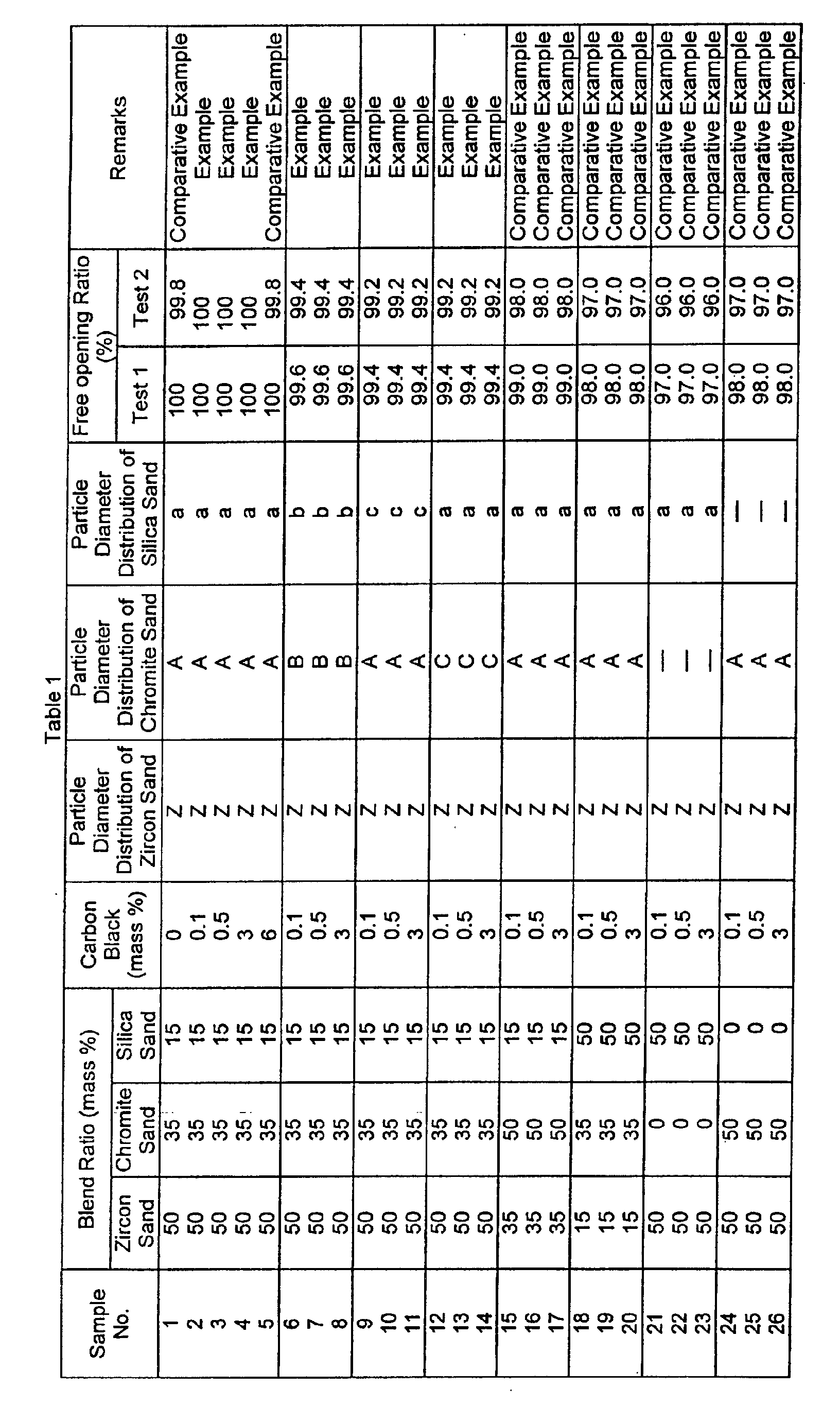
- Each of filler sands obtained by blending zircon sand, chromite sand, silica sand and carbon black in respective ratios shown in Table 1 was filled in the nozzle hole of 75 mm ⁇ in nozzle diameter of a ladle tap hole valve arranged at the bottom of a 250-ton ladle, and a free opening ratio was measured for 1000 charges.
- a process at a molten steel lead time of 200 minutes or less was performed for almost all charges.
- Test 2 a process under a severer condition of at a molten steel lead time of 300 minutes or more involving long time ladle refining was performed for 10% charges of all the charges.
- the free opening ratios obtained in these tests are also shown in Table 1.
- Sample Nos. 2 to 4 and 6 to 14 showed a high free opening ratio of 99.4% or more in Test 1, and showed a high free opening ratio of 99.2% or more in Test 2.
- Sample Nos. 2 to 4 and 6 to 8 of which the chromite sand and the silica sand had particle diameter distributions falling within respective preferred ranges showed excellent results, and among these, Sample Nos. 2 to 4 containing smaller amounts of coarse particles and fine particles showed a 100% free opening ratio in both tests.
- the pickup amount of carbon into molten steel was nearly zero, proving that these fillers could be used in making ultra low carbon steel.
- the particle diameter distributions of the zircon sand, the chromite sand and the silica sand used in Sample Nos. 2 to 4 are shown in FIG. 2.
- Sample No. 1 which contained chromite sand and silica sand in a ratio falling within the range of the present invention but no carbon black and of which the chromite sand and the silica sand had particle diameter distributions falling within the respective preferred ranges, showed an excellent free opening ratio in Test 1 but a somewhat low free opening ratio of 99.8% in Test 2, compared with the 100% free opening ratio. Also, this filler sand was sintered to the surface of the well block with high frequency and the frequency of cleaning the well block with oxygen was high, with the result that_the life of the well block greatly shortened. Sample No. 5 having a large carbon black content showed an excellent free opening ratio but was found to be unsuitable for actual use because of a large pickup amount of carbon by molten steel.
- the filler sand of the present invention is obtained by blending zircon sand, chromite sand, silica sand and carbon black in an appropriate ratio, whereby a high free opening ratio can be ensured even when a process is performed under severe conditions, such as a process at the molten steel lead time of 300 minutes or more involving long time ladle refining.
- granular carbon black having a particle diameter of 150 to 1000 ⁇ m was used.
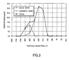
- the chromite sand and the silica sand had a particle diameter coefficient of 1.3 or less. Also, the particle diameter distributions of the chromite and silica sands used in Sample No. 27 are shown in FIG. 3.
- Each of filler sands obtained by blending chromite sand, silica sand and carbon black in respective ratios shown in Table 8 was filled in the nozzle hole of 75 mm ⁇ in nozzle diameter of a ladle tap hole valve arranged at the bottom of a 250-ton ladle, and a free opening ratio was measured for 1000 charges.
- a process at the tapping temperature of less than 1700°C and the molten steel residence time of less than 3 hours was performed for all charges.
- a process under severe conditions at a tapping temperature of 1700°C or more or a molten steel holding time of 3 hours or more involving long time ladle refining was performed for 100% charges of all the charges.
- Sample Nos. 38 to 40 and 51 to 59 corresponding to examples satisfying the ranges of the present invention showed a 100% free opening ratio in Test 3 which was conducted under the conditions that the tapping temperature and the molten steel holding time were less than 1700°C and 3 hours, respectively, and also showed an extremely high free opening ratio in Test 4 which was conducted under severer conditions that the tapping temperature was 1700°C or more or that the molten steel holding time was 3 hours or more.
- Sample Nos. 38 to 40 having an optimized ratio of the chromite and silica sands and admixed with carbon black showed a 100% free opening ratio in Test 4, proving remarkably good properties.
- Sample No. 38 containing 0.1 mass % carbon black and Sample No.. 39 containing 0.5 mass % carbon black the pickup amount of carbon into molten steel was nearly zero, proving that these filler sands can be used in making ultra low carbon steel.
- Sample Nos. 41 to 50 and 60 to 65 which did not satisfy some of the ranges of the present invention, failed to show good properties. Specifically, Sample No. 41 having a carbon black content outside the range of the present invention was found to be unsuitable for actual use because of a large pickup amount of carbon into molten steel. Also, Sample Nos. 42 to 50 of which at least one of the chromite and silica sands had a particle diameter distribution outside the range of the present invention, and Sample Nos. 60 to 65 containing either the chromite or silica sand alone with carbon black added did not show a high free opening ratio, though carbon black was added.
Landscapes
- Engineering & Computer Science (AREA)
- Mechanical Engineering (AREA)
- General Engineering & Computer Science (AREA)
- Casting Support Devices, Ladles, And Melt Control Thereby (AREA)
- Ceramic Products (AREA)
Abstract
Description


Claims (30)
- A filler sand for a ladle tap hole valve, characterized in that said filler sand contains 45 to 55 mass % of zircon sand, 30 to 40 mass % of chromite sand and 10 to 20 mass % of silica sand, and is blended externally with 0.05 to 5 mass % of carbon black calculated based on a total amount of the zircon sand, the chromite sand and the silica sand.
- The filler sand according to claim 1, wherein said filler sand is blended with 0.05 to 1 mass % of carbon black calculated based on the total amount of the zircon sand, the chromite sand and the silica sand.
- The filler sand according to claim 1, wherein 95 mass % or more of the zircon sand consists of particles having particle diameters falling within a range of 100 to 300 µm, 95 mass % or more of the chromite sand consists of particles having particle diameters falling within a range of 150 to 850 µm, 60 mass % or more of the chromite sand consists of particles having particle diameters falling within a range of 200 to 425 µm, 95 mass % or more of the silica sand consists of particles having particle diameters falling within a range of 200 to 850 µm, and 60 mass % or more of the silica sand consists of particles having particle diameters falling within a range of 300 to 600 µm.
- The filler sand according to claim 1, wherein the silica sand has a particle diameter coefficient of 1.4 or less.
- The filler sand according to claim 1, wherein the zircon sand contains substantially no particles having particle diameters smaller than 53 µm.
- The filler sand according to claim 1, wherein the chromite sand contains substantially no particles having particle diameters smaller than 53 µm.
- The filler sand according to claim 1, wherein the chromite sand contains substantially no particles having particle diameters exceeding 1180 µm.
- The filler sand according to claim 1, wherein the silica sand contains substantially no particles having particle diameters smaller than 106 µm.
- The filler sand according to claim 1, wherein the silica sand contains substantially no particles having particle diameters exceeding 1180 µm.
- The filler sand according to claim 1, wherein the carbon black is blended in a manner such that the carbon black is coated on the silica sand.
- A filler sand for a ladle tap hole valve, characterized in that said filler sand contains 30 to 90 mass % of chromite sand and 10 to 70 mass % of silica sand, 95 mass % or more of the chromite sand consists of particles having particle diameters falling within a range of 150 to 850 µm, 60 mass % or more of the chromite sand consists of particles having particle diameters falling within a range of 212 to 600 µm, 95 mass % or more of the silica sand consists of particles having particle diameters falling within a range of 300 to 1180 µm, and 90 mass % or more of the silica sand consists of particles having particle diameters falling within a range of 600 to 1180 µm.
- The filler sand according to claim 11, wherein the silica sand has a particle diameter coefficient of 1.4 or less.
- The filler sand according to claim 11, wherein the chromite sand contains substantially no particles having particle diameters 106 µm or less.
- The filler sand according to claim 11, wherein the chromite sand contains substantially no particles having particle diameters exceeding 1180 µm.
- The filler sand according to claim 11, wherein the silica sand contains substantially no particles having particle diameters smaller than 300 µm.
- The filler sand according to claim 11, wherein the silica sand contains substantially no particles having particle diameters exceeding 1700 µm.
- The filler sand according to claim 11, wherein the silica sand has an Al2O3 content of 2 mass % or less, and a total content of K2O and Na2O of 0.5 to 1.2 mass %.
- The filler sand according to claim 11, wherein the silica sand has an SiO2 content of 96 to 98 mass %.
- A filler sand for a ladle tap hole valve, characterized in that said filler sand contains 30 to 90 mass % of chromite sand and 10 to 70 mass % of silica sand and is blended externally with 0.05 to 5 mass % of carbon black calculated based on a total amount of the chromite sand and the silica sand, 95 mass % or more of the chromite sand consists of particles having particle diameters falling within a range of 150 to 850 µm, 60 mass % or more of the chromite sand consists of particles having particle diameters falling within a range of 212 to 600 µm, 95 mass % or more of the silica sand consists of particles having particle diameters falling within a range of 300 to 1180 µm, and 90 mass % or more of the silica sand consists of particles having particle diameters falling within a range of 600 to 1180 µm.
- The filler sand according to claim 19, wherein said filler sand is blended with 0.05 to 1 mass % of carbon black calculated based on the total amount of the chromite sand and the silica sand.
- The filler sand according to claim 19, wherein the silica sand has a particle diameter coefficient of 1.4 or less.
- The filler sand according to claim 19, wherein the chromite sand contains substantially no particles having particle diameters 106 µm or less.
- The filler sand according to claim 19, wherein the chromite sand contains substantially no particles having particle diameters exceeding 1180 µm.
- The filler sand according to claim 19, wherein the silica sand contains substantially no particles having particle diameters smaller than 300 µm.
- The filler sand according to claim 19, wherein the silica sand contains substantially no particles having particle diameters exceeding 1700 µm.
- The filler sand according to claim 19, wherein the carbon black is coated on the silica sand.
- The filler sand according to claim 19, wherein the silica sand has an Al2O3 content of 2 mass % or less, and a total content of K2O and Na2O of 0.5 to 1.2 mass %.
- The filler sand according to claim 19, wherein the silica sand has an SiO2 content of 96 to 98 mass %.
- The filler sand according to claim 19, wherein, for molten steel whose tapping temperature is 1700°C or more or whose molten steel holding time is 3 hours or more, the proportions of the chromite sand and the silica sand are 70 to 90 mass % and 10 to 30 mass %, respectively.
- The filler sand according to claim 19, wherein, for molten steel whose tapping temperature is less than 1700°C and whose molten steel holding time is less than 3 hours, the proportions of the chromite sand and the silica sand are 30 to 60 mass % and 40 to 70 mass %, respectively.
Applications Claiming Priority (3)
| Application Number | Priority Date | Filing Date | Title |
|---|---|---|---|
| JP14790699 | 1999-05-27 | ||
| JP14790699 | 1999-05-27 | ||
| PCT/JP2000/003345 WO2000073000A1 (en) | 1999-05-27 | 2000-05-25 | Padding sand for sliding opening/closing unit of ladle |
Publications (2)
| Publication Number | Publication Date |
|---|---|
| EP1201336A1 true EP1201336A1 (en) | 2002-05-02 |
| EP1201336A4 EP1201336A4 (en) | 2004-08-18 |
Family
ID=15440809
Family Applications (1)
| Application Number | Title | Priority Date | Filing Date |
|---|---|---|---|
| EP00929863A Withdrawn EP1201336A4 (en) | 1999-05-27 | 2000-05-25 | FILLING SAND FOR A SLIDING OPENING / CLOSING UNIT OF A POWDER |
Country Status (4)
| Country | Link |
|---|---|
| US (1) | US20020128144A1 (en) |
| EP (1) | EP1201336A4 (en) |
| JP (1) | JP3782306B2 (en) |
| WO (1) | WO2000073000A1 (en) |
Cited By (2)
| Publication number | Priority date | Publication date | Assignee | Title |
|---|---|---|---|---|
| WO2015146157A1 (en) * | 2014-03-26 | 2015-10-01 | Yamakawa Sangyo Co., Ltd. | Alumina-based filling sand for sliding nozzle |
| CN109014167A (en) * | 2018-08-27 | 2018-12-18 | 承德建龙特殊钢有限公司 | The outer guiding method of ladle draining sand and ladle open pouring technique |
Families Citing this family (10)
| Publication number | Priority date | Publication date | Assignee | Title |
|---|---|---|---|---|
| JP4641807B2 (en) * | 2005-01-24 | 2011-03-02 | Jfeスチール株式会社 | Ladle sliding opening and closing device |
| CN101972847B (en) * | 2010-09-21 | 2012-11-21 | 上海盛江特种耐火材料有限公司 | Chrome drainage sand for special steel and preparation technology thereof |
| JP6021788B2 (en) * | 2013-11-11 | 2016-11-09 | 株式会社神戸製鋼所 | How to improve the ladle natural opening rate |
| JP6021787B2 (en) * | 2013-11-11 | 2016-11-09 | 株式会社神戸製鋼所 | Evaluation and selection method of filling sand |
| CN108421970B (en) * | 2018-03-19 | 2020-05-22 | 河南通宇冶材集团有限公司 | A kind of preparation method of granular chromium drainage sand |
| CN112872347B (en) * | 2021-01-15 | 2022-07-19 | 山东钢铁集团日照有限公司 | A process for secondary filling of ladle drainage sand |
| IT202100008438A1 (en) * | 2021-04-15 | 2022-10-15 | Nico Busolini | APPARATUS AND METHOD FOR INTRODUCING CHROMITE SAND INTO THE UNLOADER OF A LADLE |
| CN113979759A (en) * | 2021-11-16 | 2022-01-28 | 中天钢铁集团有限公司 | Drainage sand suitable for high-manganese steel continuous casting production and high self-opening rate and use method |
| CN117326875A (en) * | 2022-06-27 | 2024-01-02 | 宝山钢铁股份有限公司 | Refining ladle zirconium drainage sand for high alloy steel and preparation method thereof |
| CN115156517B (en) * | 2022-08-11 | 2023-11-07 | 西峡龙成冶金材料有限公司 | Upper drainage sand and double-layer drainage sand and application thereof |
Family Cites Families (9)
| Publication number | Priority date | Publication date | Assignee | Title |
|---|---|---|---|---|
| DE3938050A1 (en) * | 1989-11-16 | 1991-05-23 | Dislich Margrit | COUPLING VALVE VALVE FOR COUPLING AND METHOD FOR THE PRODUCTION THEREOF |
| JPH0531573A (en) * | 1991-02-15 | 1993-02-09 | Shinagawa Refract Co Ltd | Packing sand for natural holing of ladle |
| JP3134018B2 (en) * | 1992-08-25 | 2001-02-13 | 東芝セラミックス株式会社 | Nozzle hole filler for molten metal flow controller |
| JPH0947863A (en) * | 1995-08-01 | 1997-02-18 | Nkk Corp | Filling filling for ladle nozzle |
| KR19990036280A (en) * | 1995-08-09 | 1999-05-25 | 미요시순키티 | Sliding nozzle filling |
| JP3216575B2 (en) * | 1996-06-07 | 2001-10-09 | 日本鋼管株式会社 | Sand filling of ladle sliding switchgear |
| BR9815515A (en) * | 1997-05-23 | 2001-07-24 | Nippon Kokan Kk | Filling sand for a borehole orifice valve |
| JPH11277220A (en) * | 1998-03-30 | 1999-10-12 | Nisshin Steel Co Ltd | Nozzle filler |
| JPH11300468A (en) * | 1998-04-20 | 1999-11-02 | Kobe Steel Ltd | Chromite-silica sand base ladle nozzle plugging sand |
-
2000
- 2000-05-25 JP JP2000621100A patent/JP3782306B2/en not_active Expired - Fee Related
- 2000-05-25 EP EP00929863A patent/EP1201336A4/en not_active Withdrawn
- 2000-05-25 WO PCT/JP2000/003345 patent/WO2000073000A1/en not_active Ceased
-
2001
- 2001-11-20 US US09/989,548 patent/US20020128144A1/en not_active Abandoned
Cited By (3)
| Publication number | Priority date | Publication date | Assignee | Title |
|---|---|---|---|---|
| WO2015146157A1 (en) * | 2014-03-26 | 2015-10-01 | Yamakawa Sangyo Co., Ltd. | Alumina-based filling sand for sliding nozzle |
| US9938194B2 (en) | 2014-03-26 | 2018-04-10 | Yamakawa Sangyo Co., Ltd. | Alumina-based filling sand for sliding nozzle |
| CN109014167A (en) * | 2018-08-27 | 2018-12-18 | 承德建龙特殊钢有限公司 | The outer guiding method of ladle draining sand and ladle open pouring technique |
Also Published As
| Publication number | Publication date |
|---|---|
| WO2000073000A1 (en) | 2000-12-07 |
| US20020128144A1 (en) | 2002-09-12 |
| EP1201336A4 (en) | 2004-08-18 |
| JP3782306B2 (en) | 2006-06-07 |
Similar Documents
| Publication | Publication Date | Title |
|---|---|---|
| EP0950452B1 (en) | Filling sand for apparatus for slidably opening and closing ladles | |
| US20020128144A1 (en) | Filler sand for a ladle tap hole valve | |
| JPWO1998052708A1 (en) | Sand packing for ladle sliding switchgear | |
| JPWO2000073000A1 (en) | Sand packing for ladle sliding switchgear | |
| JP4641807B2 (en) | Ladle sliding opening and closing device | |
| JP3216575B2 (en) | Sand filling of ladle sliding switchgear | |
| US6051514A (en) | Sliding nozzle filler | |
| EP1681114A1 (en) | Filler for ladle sliding and opening/closing device | |
| US4372779A (en) | Iron ore pellets containing coarse ore particles | |
| JPH0947863A (en) | Filling filling for ladle nozzle | |
| JPWO1997005978A1 (en) | Sliding nozzle filler | |
| JP4667110B2 (en) | Filling material for ladle sliding opening and closing device | |
| KR100461737B1 (en) | Ramming refractories for molten trough cover of blast furnace | |
| EP3887077B1 (en) | Mould powder and mould coating | |
| JP2000317625A (en) | Nozzle filler for steel making and method for producing the same | |
| JPH11300468A (en) | Chromite-silica sand base ladle nozzle plugging sand | |
| JPH07251261A (en) | Sliding nozzle filler | |
| KR20070022186A (en) | Filler for ladle sliding switch |
Legal Events
| Date | Code | Title | Description |
|---|---|---|---|
| PUAI | Public reference made under article 153(3) epc to a published international application that has entered the european phase |
Free format text: ORIGINAL CODE: 0009012 |
|
| 17P | Request for examination filed |
Effective date: 20011218 |
|
| AK | Designated contracting states |
Kind code of ref document: A1 Designated state(s): AT BE CH CY DE DK ES FI FR GB GR IE IT LI LU MC NL PT SE |
|
| RAP1 | Party data changed (applicant data changed or rights of an application transferred) |
Owner name: NKK CORPORATION Owner name: NIPPON ROTARY NOZZLE CO.,LTD. |
|
| RAP1 | Party data changed (applicant data changed or rights of an application transferred) |
Owner name: JFE STEEL CORPORATION Owner name: NIPPON ROTARY NOZZLE CO.,LTD. |
|
| RBV | Designated contracting states (corrected) |
Designated state(s): BE DE FR GB |
|
| A4 | Supplementary search report drawn up and despatched |
Effective date: 20040701 |
|
| 17Q | First examination report despatched |
Effective date: 20050216 |
|
| STAA | Information on the status of an ep patent application or granted ep patent |
Free format text: STATUS: THE APPLICATION IS DEEMED TO BE WITHDRAWN |
|
| 18D | Application deemed to be withdrawn |
Effective date: 20050628 |