EP1201178B1 - Revolving sprinkling assembly for dishwashers, provided with horizontal reciprocating motion - Google Patents
Revolving sprinkling assembly for dishwashers, provided with horizontal reciprocating motion Download PDFInfo
- Publication number
- EP1201178B1 EP1201178B1 EP20000830711 EP00830711A EP1201178B1 EP 1201178 B1 EP1201178 B1 EP 1201178B1 EP 20000830711 EP20000830711 EP 20000830711 EP 00830711 A EP00830711 A EP 00830711A EP 1201178 B1 EP1201178 B1 EP 1201178B1
- Authority
- EP
- European Patent Office
- Prior art keywords
- sprinkler
- shutter
- support arm
- sprinkling assembly
- arm
- Prior art date
- Legal status (The legal status is an assumption and is not a legal conclusion. Google has not performed a legal analysis and makes no representation as to the accuracy of the status listed.)
- Expired - Lifetime
Links
- 230000033001 locomotion Effects 0.000 title description 7
- 238000005406 washing Methods 0.000 claims description 18
- 230000010355 oscillation Effects 0.000 claims description 7
- XLYOFNOQVPJJNP-UHFFFAOYSA-N water Substances O XLYOFNOQVPJJNP-UHFFFAOYSA-N 0.000 claims description 7
- 230000005540 biological transmission Effects 0.000 claims description 5
- 230000000712 assembly Effects 0.000 description 1
- 238000000429 assembly Methods 0.000 description 1
- 230000003247 decreasing effect Effects 0.000 description 1
- 238000010586 diagram Methods 0.000 description 1
Images




Classifications
-
- A—HUMAN NECESSITIES
- A47—FURNITURE; DOMESTIC ARTICLES OR APPLIANCES; COFFEE MILLS; SPICE MILLS; SUCTION CLEANERS IN GENERAL
- A47L—DOMESTIC WASHING OR CLEANING; SUCTION CLEANERS IN GENERAL
- A47L15/00—Washing or rinsing machines for crockery or tableware
- A47L15/14—Washing or rinsing machines for crockery or tableware with stationary crockery baskets and spraying devices within the cleaning chamber
- A47L15/18—Washing or rinsing machines for crockery or tableware with stationary crockery baskets and spraying devices within the cleaning chamber with movably-mounted spraying devices
- A47L15/20—Swingable spraying devices
-
- A—HUMAN NECESSITIES
- A47—FURNITURE; DOMESTIC ARTICLES OR APPLIANCES; COFFEE MILLS; SPICE MILLS; SUCTION CLEANERS IN GENERAL
- A47L—DOMESTIC WASHING OR CLEANING; SUCTION CLEANERS IN GENERAL
- A47L15/00—Washing or rinsing machines for crockery or tableware
- A47L15/14—Washing or rinsing machines for crockery or tableware with stationary crockery baskets and spraying devices within the cleaning chamber
- A47L15/18—Washing or rinsing machines for crockery or tableware with stationary crockery baskets and spraying devices within the cleaning chamber with movably-mounted spraying devices
- A47L15/22—Rotary spraying devices
- A47L15/23—Rotary spraying devices moved by means of the sprays
Definitions
- the present invention relates to revolving sprinkling assemblies for dishwashers, and in particular to a sprinkling assembly capable of moving also with a reciprocating motion in the horizontal plane.
- conventional revolving sprinklers essentially consist of a single device pivoted on a vertical axis central shaft and provided with at least one propulsion nozzle at one end, as well as with other nozzles arranged along said device to sprinkle the dishes contained in the dishwasher rack. Since the rotation axis of said device is fixed, the resulting paths of the nozzles consist of circumferences centered on the rotation axis.
- the above-mentioned device directly sprinkles always and only the surfaces of the dishes which are along said circular paths, with a limited washing effectiveness.
- the area which can be reached by the water ejected from the nozzles approximately corresponds to the area of the square circumscribed about the circular path of the outermost nozzle.
- This solution has a first drawback of poor washing effectiveness in the end portion of the rack, since very inclined jets are unable to properly enter between the dishes arranged side by side like the almost vertical jets ejected by the other nozzles can do. Moreover, a second drawback stems from the fact that such inclined jets hit the walls of the washing space with a considerable horizontal component thus causing a significant noisiness of the dishwasher.
- the inclined jet coming out from a propulsion end nozzle of the sprinkler generates a reaction force which can be broken up in the horizontal plane into a first component along the longitudinal axis of the sprinkler and a second component along a direction perpendicular thereto. While this second component is the one which generates the rotation of the sprinkler, the component along the longitudinal axis is discharged on the shaft located at the end of the support arm. This results, therefore, in a horizontal rotation of said arm pivoted on the vertical axis of the feed duct, moving alternately from right to left and backwards according to the rotation of the sprinkler, i.e. according to the direction from which the axial component arrives on the sprinkler shaft.
- This arrangement allows to sprinkle also the outermost dishes when they are arranged in a rectangular washing space and also increases the surface directly sprinkled by the jets ejected from the nozzles thanks to the combination of the revolving motion of the sprinkler with the reciprocating motion. In this way, in fact, the nozzle paths have a much more complex development.
- the object of the present invention is to provide a revolving sprinkling assembly which overcomes the above-mentioned limitations of prior art sprinklers.
- This object is achieved by means of a sprinkling assembly wherein the ratio between the revolving frequency of the sprinkler and the oscillating frequency of the support arm is no longer one but much greater. In other words, it is possible to set a transmission ratio whereby the oscillation of the support arm occurs only every given number of rotations of the sprinkler.
- the fundamental advantage of the sprinkling assembly according to the present invention is lower noisiness and lower wear achieved thanks to the reduction of the oscillating frequency of the support arm.
- a further advantage comes from the possibility of easily setting within a certain range said transmission ratio, i.e. the time interval between the oscillations of the support arm.
- the present sprinkling assembly essentially consists of a vertical feed duct A, secured on one side of the bottom B of the washing space, at the top of which a support arm C is pivoted with a vertical axis X and carries at its free end a vertical shaft D, on which a sprinkler E is in turn centrally pivoted and has a reduced size with respect to the length of the dishwasher, as clearly resulting from the top plan views of figures 3 and 5.
- the pressurized water goes through duct A, arm C and shaft D to sprinkler E which rotates around axis Y due to at least one propulsion nozzle F (two in the illustrated example) which, differently from the above-mentioned device disclosed in EP-0727176, ejects a jet which generates a reaction force having in the horizontal plane only a component orthogonal to the longitudinal axis of the sprinkler E.
- the pivoting of sprinkler E is achieved through a lower socket which is snapped onto shaft D and externally provided with a tooth G.
- This tooth G engages at each rotation of sprinkler E with an adjacent horizontal toothed wheel H, which is integral with an underlying cylindrical shutter J provided with an opening K.
- Said shutter J is rotatably inserted within a cylindrical retaining wall L, which is in turn integral with arm C, having two opposite nozzles M, N arranged along a line orthogonal to the longitudinal axis of arm C.
- Nozzle M can be defined as front nozzle in that it faces the dishwasher door, while the opposite nozzle N facing the back of the washing space is defined rear nozzle.
- opening K arrives at nozzle N which can therefore eject a jet generating a reaction force on arm C such as to cause the rotation thereof around axis X.
- arm C oscillates towards the front portion of the washing space moving sprinkler E to the forward position illustrated in fig.3.
- the travel of arm C is obviously limited by a stop, which in the illustrated example is achieved through a horizontal peg P engaged into a slot R formed in the feed duct A.
- arm C rotates until peg P integral therewith abuts against the front end of slot R.
- a second embodiment which is different from the previous embodiment in that in wall L next to each nozzle M, N there are formed other two adjacent nozzles M', M" and N', N" respectively.
- arm C upon passage of opening K before each of said nozzles, arm C has the possibility of receiving three pulses for each forward or back shift, which may be useful in case the water pressure is low and a single pulse could therefore be insufficient to complete the oscillation of arm C.
- a third embodiment is illustrated in fig.7, which is different from the first embodiment in the position and number of openings in the rotating shutter.
- the rotating shutter U is inserted on the outside of the wall in which there are formed the front nozzle S and rear nozzle T, which are integral with arm C and formed slightly more inside with respect to shutter U.
- the latter is uninterrupted only along half of its extension whereas in the other half it has a plurality of openings V.
- This arrangement implies a greater consumption of water but reduces the risks of seizure of the sprinkler in that the play between the rotating member and the fixed member is much greater than in the preceding cases.
- duct A may be at the rear wall in case the washing space is more short than wide.
- the sprinkling assembly may be located also below or above the upper rack, by overturning it or not according to the desired position. In these cases, duct A can even come out directly from the ceiling or from the rear wall of the washing space, arm C being consequently longer or shorter.
- the number of openings in the rotating shutter and/or of nozzles, and consequently the number of pulses received by arm C at each shifting cycle can vary from the minimum illustrated in the first embodiment to the maximum illustrated in the third embodiment.
- shutter J could have two or more adjacent openings as shutter U.
- the transmission ratio can be set at the precise desired value by forming on the socket of sprinkler E even more than one tooth G, possibly arriving at a complete toothed rim which permanently engages toothed wheel H (obviously of larger size).
Landscapes
- Washing And Drying Of Tableware (AREA)
Description
- The present invention relates to revolving sprinkling assemblies for dishwashers, and in particular to a sprinkling assembly capable of moving also with a reciprocating motion in the horizontal plane.
- It is known that conventional revolving sprinklers essentially consist of a single device pivoted on a vertical axis central shaft and provided with at least one propulsion nozzle at one end, as well as with other nozzles arranged along said device to sprinkle the dishes contained in the dishwasher rack. Since the rotation axis of said device is fixed, the resulting paths of the nozzles consist of circumferences centered on the rotation axis.
- From this follows that the above-mentioned device directly sprinkles always and only the surfaces of the dishes which are along said circular paths, with a limited washing effectiveness. Moreover, the area which can be reached by the water ejected from the nozzles approximately corresponds to the area of the square circumscribed about the circular path of the outermost nozzle.
- The simplest solution in trying to overcome this latter limit is that of giving a greater inclination to the end nozzles of the sprinkler so that the water jets ejected therefrom reach beyond the area of rotation. For example, it is possible to use a sprinkler provided with a nozzle inclined at about 75° so as to cover also the foremost portion of the rack in a dishwasher whose width is smaller than its length (typically 45 x 60 cm).
- This solution has a first drawback of poor washing effectiveness in the end portion of the rack, since very inclined jets are unable to properly enter between the dishes arranged side by side like the almost vertical jets ejected by the other nozzles can do. Moreover, a second drawback stems from the fact that such inclined jets hit the walls of the washing space with a considerable horizontal component thus causing a significant noisiness of the dishwasher.
- An improvement with respect to this simple type of sprinkler is the mobile sprinkler disclosed in EP-0727176 which is pivoted on a shaft located at the end of a support arm which is in turn vertically pivoted at its other end to a feed duct integral with the washing space. This support arm is therefore provided also with a horizontal reciprocating motion generated by the sprinkler itself due to the distance between the axis of the shaft on which it is pivoted and the point where the support arm is pivoted on the feed duct.
- In fact, the inclined jet coming out from a propulsion end nozzle of the sprinkler generates a reaction force which can be broken up in the horizontal plane into a first component along the longitudinal axis of the sprinkler and a second component along a direction perpendicular thereto. While this second component is the one which generates the rotation of the sprinkler, the component along the longitudinal axis is discharged on the shaft located at the end of the support arm. This results, therefore, in a horizontal rotation of said arm pivoted on the vertical axis of the feed duct, moving alternately from right to left and backwards according to the rotation of the sprinkler, i.e. according to the direction from which the axial component arrives on the sprinkler shaft.
- This arrangement allows to sprinkle also the outermost dishes when they are arranged in a rectangular washing space and also increases the surface directly sprinkled by the jets ejected from the nozzles thanks to the combination of the revolving motion of the sprinkler with the reciprocating motion. In this way, in fact, the nozzle paths have a much more complex development.
- However even this arrangement is not free from drawbacks in that in this type of structure the revolving and reciprocating motions of the sprinkler are mutually bound, i.e. at each rotation of the sprinkler corresponds a translation thereof due to the oscillation of the support arm. This implies that a high revolving frequency of the sprinkler corresponds to a high oscillating frequency of the support arm and therefore to a certain noisiness since the support arm hits the end stops at the end of each travel. Moreover, it is impossible to reduce said oscillating frequency of the arm without decreasing the revolving speed of the sprinkler thus negatively affecting the washing effectiveness.
- Therefore, the object of the present invention is to provide a revolving sprinkling assembly which overcomes the above-mentioned limitations of prior art sprinklers.
- This object is achieved by means of a sprinkling assembly wherein the ratio between the revolving frequency of the sprinkler and the oscillating frequency of the support arm is no longer one but much greater. In other words, it is possible to set a transmission ratio whereby the oscillation of the support arm occurs only every given number of rotations of the sprinkler.
- The fundamental advantage of the sprinkling assembly according to the present invention is lower noisiness and lower wear achieved thanks to the reduction of the oscillating frequency of the support arm.
- A further advantage comes from the possibility of easily setting within a certain range said transmission ratio, i.e. the time interval between the oscillations of the support arm.
- These and other advantages and characteristics of the sprinkling assembly according to the present invention will be clear to those skilled in the art from the following detailed description of some embodiments thereof, with reference to the annexed drawings wherein:
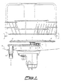
- Fig.1 is a diagrammatic partially sectional front view of a first embodiment of the sprinkling assembly located on the bottom of the washing space of a dishwasher whose width is smaller than its length;
- Figs.2a, 2b and 2c are partial top plan views of the above-mentioned sprinkling assembly at a back position;
- Fig.3 is a diagrammatic top plan view of the sprinkling assembly at a forward position;
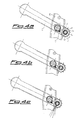
- Figs.4a, 4b and 4c are partial top plan views of the above-mentioned sprinkling assembly at a forward position;
- Fig.5 is a diagrammatic top plan view of the sprinkling assembly at a back position;
- Fig.6 is a partial top plan view of a second embodiment of the sprinkling assembly; and
- Fig.7 is a partial top plan view of a third embodiment of the sprinkling assembly.
-
- With reference to figures 1 to 5, there is seen that the present sprinkling assembly essentially consists of a vertical feed duct A, secured on one side of the bottom B of the washing space, at the top of which a support arm C is pivoted with a vertical axis X and carries at its free end a vertical shaft D, on which a sprinkler E is in turn centrally pivoted and has a reduced size with respect to the length of the dishwasher, as clearly resulting from the top plan views of figures 3 and 5.
- The pressurized water goes through duct A, arm C and shaft D to sprinkler E which rotates around axis Y due to at least one propulsion nozzle F (two in the illustrated example) which, differently from the above-mentioned device disclosed in EP-0727176, ejects a jet which generates a reaction force having in the horizontal plane only a component orthogonal to the longitudinal axis of the sprinkler E.
- The pivoting of sprinkler E is achieved through a lower socket which is snapped onto shaft D and externally provided with a tooth G. This tooth G engages at each rotation of sprinkler E with an adjacent horizontal toothed wheel H, which is integral with an underlying cylindrical shutter J provided with an opening K. Said shutter J is rotatably inserted within a cylindrical retaining wall L, which is in turn integral with arm C, having two opposite nozzles M, N arranged along a line orthogonal to the longitudinal axis of arm C. Nozzle M can be defined as front nozzle in that it faces the dishwasher door, while the opposite nozzle N facing the back of the washing space is defined rear nozzle.
- From the description above and from the operating diagrams of figures 2-5, the simple and reliable operation of the sprinkling assembly according to the invention can be readily understood.
- Assuming that nozzles F are oriented to rotate sprinkler E clockwise (as seen from above), it follows that tooth G at each rotation causes a partial counterclockwise rotation of the toothed wheel H. The number of rotations of sprinkler E corresponding to a complete rotation of toothed wheel H is obviously defined by the transmission ratio between said members, namely in practice by the number of teeth of wheel H (12 in the illustrated example).
- Consider to start from the position of fig.2a where arm C is at the back position in the washing space and opening K of shutter J has just passed beyond the front nozzle M, thus moving towards the rear nozzle N. After four rotations of sprinkler E, and as many partial rotations of wheel H due to tooth G, opening K arrives close to the rear nozzle N as shown in fig.2b.
- Upon the following rotation, opening K arrives at nozzle N which can therefore eject a jet generating a reaction force on arm C such as to cause the rotation thereof around axis X. As a consequence, arm C oscillates towards the front portion of the washing space moving sprinkler E to the forward position illustrated in fig.3. The travel of arm C is obviously limited by a stop, which in the illustrated example is achieved through a horizontal peg P engaged into a slot R formed in the feed duct A. In other words, arm C rotates until peg P integral therewith abuts against the front end of slot R.
- The oscillating cycle of arm C is completed by the similar reverse motion depicted in figures 4 and 5.
- Starting from the position of fig.4a where arm C is at the forward position and opening K has just passed beyond the rear nozzle N, after four rotations of sprinkler E opening K arrives close to the front nozzle M (fig.4b) and upon the following rotation it arrives at said nozzle which can therefore eject a jet causing the rotation of arm C towards the rear portion of the washing space. Sprinkler E is thus moved to the back position illustrated in fig.5, the rotation of arm C being obviously halted when peg P abuts against the rear end of slot R.
- Therefore it is clear how this simple structural arrangement allows to move sprinkler E only every 6 rotations, and it is also clear that it is sufficient to change the number of teeth of wheel H to change said moving interval. For example, when using a wheel with 14, 16 or 18 teeth then 7, 8 or 9 rotations respectively would be required to move sprinkler E between one position and the other. The arrangement described above is the simplest, but obviously other similar arrangements are possible.
- For example, in fig.6 there is illustrated a second embodiment which is different from the previous embodiment in that in wall L next to each nozzle M, N there are formed other two adjacent nozzles M', M" and N', N" respectively. In this way, upon passage of opening K before each of said nozzles, arm C has the possibility of receiving three pulses for each forward or back shift, which may be useful in case the water pressure is low and a single pulse could therefore be insufficient to complete the oscillation of arm C.
- A third embodiment is illustrated in fig.7, which is different from the first embodiment in the position and number of openings in the rotating shutter. In this case, the rotating shutter U is inserted on the outside of the wall in which there are formed the front nozzle S and rear nozzle T, which are integral with arm C and formed slightly more inside with respect to shutter U. The latter is uninterrupted only along half of its extension whereas in the other half it has a plurality of openings V. In practice this results in a continuous delivery of water through the two nozzles S, T but only one of them is capable of generating a reaction force since the other jet is blocked by the uninterrupted portion of shutter U. This arrangement implies a greater consumption of water but reduces the risks of seizure of the sprinkler in that the play between the rotating member and the fixed member is much greater than in the preceding cases.
- It should be noted that the illustrated embodiments concerning a sprinkling assembly secured on a side of the washing space are mere examples, in that the same structure can be applied in several other ways. First of all, duct A may be at the rear wall in case the washing space is more short than wide. Secondly, the sprinkling assembly may be located also below or above the upper rack, by overturning it or not according to the desired position. In these cases, duct A can even come out directly from the ceiling or from the rear wall of the washing space, arm C being consequently longer or shorter.
- Furthermore, it is clear that the number of openings in the rotating shutter and/or of nozzles, and consequently the number of pulses received by arm C at each shifting cycle, can vary from the minimum illustrated in the first embodiment to the maximum illustrated in the third embodiment. For example, shutter J could have two or more adjacent openings as shutter U.
- Finally, the transmission ratio can be set at the precise desired value by forming on the socket of sprinkler E even more than one tooth G, possibly arriving at a complete toothed rim which permanently engages toothed wheel H (obviously of larger size).
Claims (6)
- A revolving sprinkling assembly for a dishwasher including at least a sprinkler (E) provided with at least one propulsion nozzle (F) intended for rotating the sprinkler (E), the latter being pivoted at an end of a support arm (C) through which water under pressure is fed, said support arm (C) being in turn vertically pivotably disposed at its other end to a feed duct (A) integral with the washing space so as to allow an oscillation of said support arm (C), the oscillation of the support arm (C) being limited by a pair of stop means, characterized in that said at least one propulsion nozzle (F) generates a reaction force having in the horizontal plane only a component orthogonal to the longitudinal axis of said sprinkler (E), and in that the support arm (C) is provided with at least two oppositely disposed nozzles (M, N; S, T) suitable to eject jets having a component orthogonal to the longitudinal axis of said arm (C), the emission of said jets being controlled by a rotating shutter (J; U) provided with at least one opening (K; V), the rotation of said shutter (J; U) being controlled by the rotation of the sprinkler (E) according to a transmission ratio greater then unity.
- A sprinkling assembly according to claim 1, characterized in that the rotation of the shutter (J; U) is controlled by the sprinkler (E) through a lower socket provided at its exterior surface with at least one tooth (G) suitable to engage with an adjacent horizontal toothed wheel (H) which is integral with the shutter (J; U).
- A sprinkling assembly according to claim 2, characterized in that the shutter (J) is inserted within a cylindrical wall in which there are formed the two opposite nozzles (M, N).
- A sprinkling assembly according to claim 2, characterized in that the shutter (U) is inserted at the exterior surface of a cylindrical retaining wall (L) of the support arm (C) in which there are formed the two opposite nozzles (S, T) slightly more inside with respect to the shutter (U).
- A sprinkling assembly according to one or more of the preceding claims, characterized in that the stops means which limit the oscillation of the support arm (C) include a horizontal peg (P) integral with said arm (C) and engageable in of a horizontal slot (R) formed in the feed duct (A).
- A dishwasher with a rectangular washing space, characterized in that it includes at least one sprinkling assembly according to one or more of the preceding claims arranged on one of the long sides of the washing space.
Priority Applications (3)
| Application Number | Priority Date | Filing Date | Title |
|---|---|---|---|
| ES00830711T ES2174812T3 (en) | 2000-10-27 | 2000-10-27 | SPRAY SPRAY SET FOR DISHWASHERS, PROVIDED WITH MOVEMENT OF HORIZONTAL VAIVEN. |
| EP20000830711 EP1201178B1 (en) | 2000-10-27 | 2000-10-27 | Revolving sprinkling assembly for dishwashers, provided with horizontal reciprocating motion |
| DE2000600170 DE60000170T2 (en) | 2000-10-27 | 2000-10-27 | Rotating spray device for dishwasher with horizontal reciprocating movement |
Applications Claiming Priority (1)
| Application Number | Priority Date | Filing Date | Title |
|---|---|---|---|
| EP20000830711 EP1201178B1 (en) | 2000-10-27 | 2000-10-27 | Revolving sprinkling assembly for dishwashers, provided with horizontal reciprocating motion |
Publications (2)
| Publication Number | Publication Date |
|---|---|
| EP1201178A1 EP1201178A1 (en) | 2002-05-02 |
| EP1201178B1 true EP1201178B1 (en) | 2002-05-15 |
Family
ID=8175526
Family Applications (1)
| Application Number | Title | Priority Date | Filing Date |
|---|---|---|---|
| EP20000830711 Expired - Lifetime EP1201178B1 (en) | 2000-10-27 | 2000-10-27 | Revolving sprinkling assembly for dishwashers, provided with horizontal reciprocating motion |
Country Status (3)
| Country | Link |
|---|---|
| EP (1) | EP1201178B1 (en) |
| DE (1) | DE60000170T2 (en) |
| ES (1) | ES2174812T3 (en) |
Families Citing this family (3)
| Publication number | Priority date | Publication date | Assignee | Title |
|---|---|---|---|---|
| ES2405792T3 (en) | 2011-03-01 | 2013-06-03 | Bonferraro S.P.A. | Device for the projection of liquids for dishwashing machines, comprising an oscillating secondary projection device |
| EP3629872B1 (en) * | 2017-06-02 | 2025-12-10 | Arçelik Anonim Sirketi | Liquid spraying device for a dishwasher with improved cleaning performance |
| CN111772550B (en) * | 2020-07-23 | 2025-01-03 | 浙江中仪欧格电器有限公司 | Unmanned automatic tableware loading and unloading system |
Family Cites Families (6)
| Publication number | Priority date | Publication date | Assignee | Title |
|---|---|---|---|---|
| GB833434A (en) * | 1957-08-21 | 1960-04-27 | Sven Gustaf Nord | Dishwashing apparatus |
| US5477874A (en) * | 1993-08-13 | 1995-12-26 | Matsushita Electric Industrial Co., Ltd. | Dishwasher |
| DE4416655A1 (en) * | 1994-05-11 | 1995-11-16 | Heinz Gutoehrlein | Spray arm for domestic electric dishwashing machine |
| IT235026Y1 (en) * | 1994-06-16 | 2000-03-31 | Zanussi Elettrodomestici | DISHWASHER WITH ROTATING SPRAY REEL |
| IT1275156B (en) * | 1995-02-15 | 1997-07-30 | Smeg Spa | REVOLVING DISHWASHER GROUP FOR DISHWASHER EQUIPPED WITH A HORIZONTAL ALTERNATE MOTOR |
| IT1275155B (en) * | 1995-02-15 | 1997-07-30 | Smeg Spa | REVOLVING DISHWASHER GROUP FOR DISHWASHER EQUIPPED WITH A HORIZONTAL ALTERNATE MOTOR |
-
2000
- 2000-10-27 DE DE2000600170 patent/DE60000170T2/en not_active Expired - Lifetime
- 2000-10-27 EP EP20000830711 patent/EP1201178B1/en not_active Expired - Lifetime
- 2000-10-27 ES ES00830711T patent/ES2174812T3/en not_active Expired - Lifetime
Also Published As
| Publication number | Publication date |
|---|---|
| DE60000170T2 (en) | 2003-01-30 |
| EP1201178A1 (en) | 2002-05-02 |
| ES2174812T3 (en) | 2002-11-16 |
| DE60000170D1 (en) | 2002-07-11 |
Similar Documents
| Publication | Publication Date | Title |
|---|---|---|
| EP2494906B1 (en) | Sprinkling assembly for dishwashers comprising a secondary oscillating sprinkler | |
| EP1090579B1 (en) | Revolving sprinkling assembly for dishwasher provided with a device for horizontal shift | |
| EP1847207A3 (en) | Wash/rinse system for a drawer-type dishwasher | |
| EP3393327B1 (en) | Dishwasher comprising a wash arm arrangement | |
| EP0727177B1 (en) | Revolving sprinkling assembly for dishwashers, provided with horizontal reciprocating motion | |
| EP1201178A1 (en) | Revolving sprinkling assembly for dishwashers, provided with horizontal reciprocating motion | |
| CA2266247A1 (en) | An improved design of the nozzle arrangement on the spray tube of the conventional, oscillating lawn or hose sprinkler | |
| EP1132039A2 (en) | Revolving sprinkling assembly for dishwasher, provided with a device for horizontal shift | |
| KR200156558Y1 (en) | Spray arm of dishwasher | |
| EP0727176B1 (en) | Revolving sprinkling assembly for dishwashers, provided with horizontal reciprocating motion | |
| JP2782943B2 (en) | Dishwasher | |
| EP0474127A1 (en) | Improved dishwashing machine | |
| JP4726533B2 (en) | Spray nozzle for dishwasher | |
| JPH04338438A (en) | Dishwasher | |
| JP3415666B2 (en) | Washing nozzle in dishwasher | |
| JPH01135551A (en) | Multi-step spraying nozzle apparatus | |
| JP2011050782A (en) | Spray nozzle for dishwasher | |
| KR0122265Y1 (en) | Washing water spraying device for dish washer | |
| KR200433682Y1 (en) | Injector with rocking nozzle | |
| JP2772382B2 (en) | Liquid injection device | |
| KR200146272Y1 (en) | Rotary sprayers for dishwashers | |
| CN220344348U (en) | Spraying structure for cleaning machine and cleaning machine | |
| JPH0737725Y2 (en) | Sprinkler | |
| KR930000007Y1 (en) | Apparatus for cleansing tableware | |
| JP2002065559A (en) | Dishwasher |
Legal Events
| Date | Code | Title | Description |
|---|---|---|---|
| GRAG | Despatch of communication of intention to grant |
Free format text: ORIGINAL CODE: EPIDOS AGRA |
|
| GRAG | Despatch of communication of intention to grant |
Free format text: ORIGINAL CODE: EPIDOS AGRA |
|
| GRAH | Despatch of communication of intention to grant a patent |
Free format text: ORIGINAL CODE: EPIDOS IGRA |
|
| GRAH | Despatch of communication of intention to grant a patent |
Free format text: ORIGINAL CODE: EPIDOS IGRA |
|
| PUAI | Public reference made under article 153(3) epc to a published international application that has entered the european phase |
Free format text: ORIGINAL CODE: 0009012 |
|
| GRAA | (expected) grant |
Free format text: ORIGINAL CODE: 0009210 |
|
| 17P | Request for examination filed |
Effective date: 20010518 |
|
| AK | Designated contracting states |
Kind code of ref document: A1 Designated state(s): AT BE CH CY DE DK ES FI FR GB GR IE IT LI LU MC NL PT SE |
|
| AX | Request for extension of the european patent |
Free format text: AL;LT;LV;MK;RO;SI |
|
| AK | Designated contracting states |
Kind code of ref document: B1 Designated state(s): DE ES FR GB IT SE |
|
| AX | Request for extension of the european patent |
Free format text: AL;LT;LV;MK;RO;SI |
|
| LTIE | Lt: invalidation of european patent or patent extension |
Inventor name: TANAKA, YOSHINORI, UNI-CHARM CO., LTD. |
|
| REG | Reference to a national code |
Ref country code: GB Ref legal event code: FG4D |
|
| REG | Reference to a national code |
Ref country code: IE Ref legal event code: FG4D |
|
| REF | Corresponds to: |
Ref document number: 60000170 Country of ref document: DE Date of ref document: 20020711 |
|
| REG | Reference to a national code |
Ref country code: ES Ref legal event code: FG2A Ref document number: 2174812 Country of ref document: ES Kind code of ref document: T3 |
|
| AKX | Designation fees paid |
Free format text: DE ES FR GB IT SE |
|
| PLBE | No opposition filed within time limit |
Free format text: ORIGINAL CODE: 0009261 |
|
| STAA | Information on the status of an ep patent application or granted ep patent |
Free format text: STATUS: NO OPPOSITION FILED WITHIN TIME LIMIT |
|
| 26N | No opposition filed |
Effective date: 20030218 |
|
| REG | Reference to a national code |
Ref country code: IE Ref legal event code: MM4A |
|
| PGFP | Annual fee paid to national office [announced via postgrant information from national office to epo] |
Ref country code: SE Payment date: 20081014 Year of fee payment: 9 |
|
| PGFP | Annual fee paid to national office [announced via postgrant information from national office to epo] |
Ref country code: ES Payment date: 20091023 Year of fee payment: 10 |
|
| EUG | Se: european patent has lapsed | ||
| PG25 | Lapsed in a contracting state [announced via postgrant information from national office to epo] |
Ref country code: SE Free format text: LAPSE BECAUSE OF NON-PAYMENT OF DUE FEES Effective date: 20091028 |
|
| REG | Reference to a national code |
Ref country code: ES Ref legal event code: FD2A Effective date: 20111219 |
|
| PG25 | Lapsed in a contracting state [announced via postgrant information from national office to epo] |
Ref country code: ES Free format text: LAPSE BECAUSE OF NON-PAYMENT OF DUE FEES Effective date: 20101028 |
|
| REG | Reference to a national code |
Ref country code: FR Ref legal event code: PLFP Year of fee payment: 16 |
|
| REG | Reference to a national code |
Ref country code: FR Ref legal event code: PLFP Year of fee payment: 17 |
|
| REG | Reference to a national code |
Ref country code: FR Ref legal event code: PLFP Year of fee payment: 18 |
|
| REG | Reference to a national code |
Ref country code: FR Ref legal event code: PLFP Year of fee payment: 19 |
|
| PGFP | Annual fee paid to national office [announced via postgrant information from national office to epo] |
Ref country code: BE Payment date: 20181121 Year of fee payment: 16 |
|
| PGFP | Annual fee paid to national office [announced via postgrant information from national office to epo] |
Ref country code: DE Payment date: 20191021 Year of fee payment: 20 |
|
| PGFP | Annual fee paid to national office [announced via postgrant information from national office to epo] |
Ref country code: FR Payment date: 20191028 Year of fee payment: 20 Ref country code: IT Payment date: 20191016 Year of fee payment: 20 |
|
| GBPC | Gb: european patent ceased through non-payment of renewal fee |
Effective date: 20191027 |
|
| REG | Reference to a national code |
Ref country code: DE Ref legal event code: R071 Ref document number: 60000170 Country of ref document: DE |
|
| PG25 | Lapsed in a contracting state [announced via postgrant information from national office to epo] |
Ref country code: GB Free format text: LAPSE BECAUSE OF NON-PAYMENT OF DUE FEES Effective date: 20191027 |