EP1201176A1 - Disposable dirt wiping-out implement and production method therefor - Google Patents
Disposable dirt wiping-out implement and production method therefor Download PDFInfo
- Publication number
- EP1201176A1 EP1201176A1 EP00915498A EP00915498A EP1201176A1 EP 1201176 A1 EP1201176 A1 EP 1201176A1 EP 00915498 A EP00915498 A EP 00915498A EP 00915498 A EP00915498 A EP 00915498A EP 1201176 A1 EP1201176 A1 EP 1201176A1
- Authority
- EP
- European Patent Office
- Prior art keywords
- melting point
- sheath
- conjugated fiber
- base sheet
- sheet
- Prior art date
- Legal status (The legal status is an assumption and is not a legal conclusion. Google has not performed a legal analysis and makes no representation as to the accuracy of the status listed.)
- Granted
Links
Images



Classifications
-
- A—HUMAN NECESSITIES
- A47—FURNITURE; DOMESTIC ARTICLES OR APPLIANCES; COFFEE MILLS; SPICE MILLS; SUCTION CLEANERS IN GENERAL
- A47L—DOMESTIC WASHING OR CLEANING; SUCTION CLEANERS IN GENERAL
- A47L13/00—Implements for cleaning floors, carpets, furniture, walls, or wall coverings
- A47L13/10—Scrubbing; Scouring; Cleaning; Polishing
- A47L13/16—Cloths; Pads; Sponges
-
- A—HUMAN NECESSITIES
- A47—FURNITURE; DOMESTIC ARTICLES OR APPLIANCES; COFFEE MILLS; SPICE MILLS; SUCTION CLEANERS IN GENERAL
- A47L—DOMESTIC WASHING OR CLEANING; SUCTION CLEANERS IN GENERAL
- A47L13/00—Implements for cleaning floors, carpets, furniture, walls, or wall coverings
- A47L13/10—Scrubbing; Scouring; Cleaning; Polishing
- A47L13/20—Mops
-
- Y—GENERAL TAGGING OF NEW TECHNOLOGICAL DEVELOPMENTS; GENERAL TAGGING OF CROSS-SECTIONAL TECHNOLOGIES SPANNING OVER SEVERAL SECTIONS OF THE IPC; TECHNICAL SUBJECTS COVERED BY FORMER USPC CROSS-REFERENCE ART COLLECTIONS [XRACs] AND DIGESTS
- Y10—TECHNICAL SUBJECTS COVERED BY FORMER USPC
- Y10T—TECHNICAL SUBJECTS COVERED BY FORMER US CLASSIFICATION
- Y10T442/00—Fabric [woven, knitted, or nonwoven textile or cloth, etc.]
- Y10T442/60—Nonwoven fabric [i.e., nonwoven strand or fiber material]
- Y10T442/608—Including strand or fiber material which is of specific structural definition
- Y10T442/627—Strand or fiber material is specified as non-linear [e.g., crimped, coiled, etc.]
-
- Y—GENERAL TAGGING OF NEW TECHNOLOGICAL DEVELOPMENTS; GENERAL TAGGING OF CROSS-SECTIONAL TECHNOLOGIES SPANNING OVER SEVERAL SECTIONS OF THE IPC; TECHNICAL SUBJECTS COVERED BY FORMER USPC CROSS-REFERENCE ART COLLECTIONS [XRACs] AND DIGESTS
- Y10—TECHNICAL SUBJECTS COVERED BY FORMER USPC
- Y10T—TECHNICAL SUBJECTS COVERED BY FORMER US CLASSIFICATION
- Y10T442/00—Fabric [woven, knitted, or nonwoven textile or cloth, etc.]
- Y10T442/60—Nonwoven fabric [i.e., nonwoven strand or fiber material]
- Y10T442/608—Including strand or fiber material which is of specific structural definition
- Y10T442/627—Strand or fiber material is specified as non-linear [e.g., crimped, coiled, etc.]
- Y10T442/629—Composite strand or fiber material
-
- Y—GENERAL TAGGING OF NEW TECHNOLOGICAL DEVELOPMENTS; GENERAL TAGGING OF CROSS-SECTIONAL TECHNOLOGIES SPANNING OVER SEVERAL SECTIONS OF THE IPC; TECHNICAL SUBJECTS COVERED BY FORMER USPC CROSS-REFERENCE ART COLLECTIONS [XRACs] AND DIGESTS
- Y10—TECHNICAL SUBJECTS COVERED BY FORMER USPC
- Y10T—TECHNICAL SUBJECTS COVERED BY FORMER US CLASSIFICATION
- Y10T442/00—Fabric [woven, knitted, or nonwoven textile or cloth, etc.]
- Y10T442/60—Nonwoven fabric [i.e., nonwoven strand or fiber material]
- Y10T442/637—Including strand or fiber material which is a monofilament composed of two or more polymeric materials in physically distinct relationship [e.g., sheath-core, side-by-side, islands-in-sea, fibrils-in-matrix, etc.] or composed of physical blend of chemically different polymeric materials or a physical blend of a polymeric material and a filler material
-
- Y—GENERAL TAGGING OF NEW TECHNOLOGICAL DEVELOPMENTS; GENERAL TAGGING OF CROSS-SECTIONAL TECHNOLOGIES SPANNING OVER SEVERAL SECTIONS OF THE IPC; TECHNICAL SUBJECTS COVERED BY FORMER USPC CROSS-REFERENCE ART COLLECTIONS [XRACs] AND DIGESTS
- Y10—TECHNICAL SUBJECTS COVERED BY FORMER USPC
- Y10T—TECHNICAL SUBJECTS COVERED BY FORMER US CLASSIFICATION
- Y10T442/00—Fabric [woven, knitted, or nonwoven textile or cloth, etc.]
- Y10T442/60—Nonwoven fabric [i.e., nonwoven strand or fiber material]
- Y10T442/637—Including strand or fiber material which is a monofilament composed of two or more polymeric materials in physically distinct relationship [e.g., sheath-core, side-by-side, islands-in-sea, fibrils-in-matrix, etc.] or composed of physical blend of chemically different polymeric materials or a physical blend of a polymeric material and a filler material
- Y10T442/641—Sheath-core multicomponent strand or fiber material
-
- Y—GENERAL TAGGING OF NEW TECHNOLOGICAL DEVELOPMENTS; GENERAL TAGGING OF CROSS-SECTIONAL TECHNOLOGIES SPANNING OVER SEVERAL SECTIONS OF THE IPC; TECHNICAL SUBJECTS COVERED BY FORMER USPC CROSS-REFERENCE ART COLLECTIONS [XRACs] AND DIGESTS
- Y10—TECHNICAL SUBJECTS COVERED BY FORMER USPC
- Y10T—TECHNICAL SUBJECTS COVERED BY FORMER US CLASSIFICATION
- Y10T442/00—Fabric [woven, knitted, or nonwoven textile or cloth, etc.]
- Y10T442/60—Nonwoven fabric [i.e., nonwoven strand or fiber material]
- Y10T442/659—Including an additional nonwoven fabric
- Y10T442/66—Additional nonwoven fabric is a spun-bonded fabric
-
- Y—GENERAL TAGGING OF NEW TECHNOLOGICAL DEVELOPMENTS; GENERAL TAGGING OF CROSS-SECTIONAL TECHNOLOGIES SPANNING OVER SEVERAL SECTIONS OF THE IPC; TECHNICAL SUBJECTS COVERED BY FORMER USPC CROSS-REFERENCE ART COLLECTIONS [XRACs] AND DIGESTS
- Y10—TECHNICAL SUBJECTS COVERED BY FORMER USPC
- Y10T—TECHNICAL SUBJECTS COVERED BY FORMER US CLASSIFICATION
- Y10T442/00—Fabric [woven, knitted, or nonwoven textile or cloth, etc.]
- Y10T442/60—Nonwoven fabric [i.e., nonwoven strand or fiber material]
- Y10T442/659—Including an additional nonwoven fabric
- Y10T442/668—Separate nonwoven fabric layers comprise chemically different strand or fiber material
-
- Y—GENERAL TAGGING OF NEW TECHNOLOGICAL DEVELOPMENTS; GENERAL TAGGING OF CROSS-SECTIONAL TECHNOLOGIES SPANNING OVER SEVERAL SECTIONS OF THE IPC; TECHNICAL SUBJECTS COVERED BY FORMER USPC CROSS-REFERENCE ART COLLECTIONS [XRACs] AND DIGESTS
- Y10—TECHNICAL SUBJECTS COVERED BY FORMER USPC
- Y10T—TECHNICAL SUBJECTS COVERED BY FORMER US CLASSIFICATION
- Y10T442/00—Fabric [woven, knitted, or nonwoven textile or cloth, etc.]
- Y10T442/60—Nonwoven fabric [i.e., nonwoven strand or fiber material]
- Y10T442/674—Nonwoven fabric with a preformed polymeric film or sheet
-
- Y—GENERAL TAGGING OF NEW TECHNOLOGICAL DEVELOPMENTS; GENERAL TAGGING OF CROSS-SECTIONAL TECHNOLOGIES SPANNING OVER SEVERAL SECTIONS OF THE IPC; TECHNICAL SUBJECTS COVERED BY FORMER USPC CROSS-REFERENCE ART COLLECTIONS [XRACs] AND DIGESTS
- Y10—TECHNICAL SUBJECTS COVERED BY FORMER USPC
- Y10T—TECHNICAL SUBJECTS COVERED BY FORMER US CLASSIFICATION
- Y10T442/00—Fabric [woven, knitted, or nonwoven textile or cloth, etc.]
- Y10T442/60—Nonwoven fabric [i.e., nonwoven strand or fiber material]
- Y10T442/681—Spun-bonded nonwoven fabric
Definitions
- This invention relates to a disposable wipe-out sheet suitable for wiping out dust and/or dirt from floor or wall surfaces.
- Japanese Patent Application Publication No. 1997-135798 describes a disposable wipe-out sheet comprising a heat-sealable synthetic resin base sheet and a plurality of heat-sealable filaments bonded to the base sheet and extending in one direction.
- These filaments are obtained by deregistering or opening a tow of continuous filaments and bonded to the base sheet by a plurality of sealing lines extending transversely of the filaments and arranged intermittently in the one direction.
- An assembly of these filaments obtained by deregistering the two is bulky and, along the sealing lines formed by locally pressing this assembly under heating, a plurality of filaments are molten and solidified to form a high density film bonded to the base sheet. Between each pair of the adjacent sealing lines, filaments form convex bridge-like portions describing arcs which are convex upward from the base sheet.
- One of measures to improve a productivity per unit time of the wipe-out sheet of prior art is to feed the heat-sealable synthetic resin base sheet and the filaments at a high velocity onto a production line so that the base sheet and filaments may be heat-sealed together at a high velocity corresponding to said high feeding velocity.
- synthetic resin having a relatively low melting point for both the base sheet and the filaments and to use the press having high temperature and pressure.
- a temperature of the press is adjusted to a level substantially higher than the melting point of the synthetic resin, both the base sheet and the filaments would be deformed due to heat transferred from the press in their regions other than their regions in which the sheet and the filaments.
- a disposable wipe-out sheet comprising a heat-sealable synthetic resin base sheet and a plurality of heat-sealable synthetic resin long fibers heat-sealed with the base sheet and extending in one direction, wherein the long fibers are heat-sealed with the base sheet by a plurality of sealing lines arranged intermittently in the one direction, wherein: the long fibers comprise core-sheath type conjugated fibers wherein a melting point of the sheath is lower than a melting point of the core and such difference of the melting points is at least by 30 °C.
- a process for making a disposable wipe-out sheet comprising a heat-sealable synthetic resin base sheet and a plurality of heat-sealable synthetic resin long fibers heat-sealed with the base sheet and extending in one direction, wherein said long fibers are heat-sealed with the base sheet by a plurality of sealing lines arranged intermittently in the one direction, wherein:
- Fig. 1 is a perspective view showing a holder 2 with a disposable wipe-out sheet 1 attached thereto.
- the holder 2 comprises a base plate 3 and a stick 4.
- the wipe-out sheet 1 placed against the lower surface of the base plate 3 has its opposite long side edge regions 7 folded back onto the upper surface of the base plate 3 and fastened to the upper surface by means of clips 8 mounted on the base plate 3. Dust and/or dirt on floor or wall surfaces may be wiped out by the wipe-out sheet 1 attached to the holder 2 with the stick 4 gripped in user's hands.
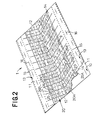
- Fig. 2 is a perspective view showing the same wipe-out sheet 1 as the wipe-out sheet 1 shown by Fig. 1 as partially broken away.
- the wipe-out sheet 1 is herein illustrated as have been detached from the base plate 3 and developed with its wiper surface facing upward.
- the wipe-out sheet 1 comprises a base sheet layer 10 made of a heat-sealable synthetic resin film or nonwoven fabric and a wiper layer 20 formed by a plurality of heat-sealable long fibers or filaments 25 bonded to the upper surface of the base sheet layer 10.
- the base sheet layer 10 is of a rectangular shape defined by a pair of opposite long side edge regions 11 extending parallel to each other and a pair of opposite short side edges 12 extending also parallel to each other.
- Band-like reinforcing sheets 13 made of a synthetic resin film are heat-sealed with the opposite side edge regions 11 at a plurality of spots 15 in order to improve a tear strength of these side edge regions 11.
- a pair of opposite side edge regions of the wiper layer 20 are covered with inner edge regions 14 of the respective reinforcing sheets 13.
- the side edge regions 11 of the base sheet layer 10 are formed with a plurality of slits 16 extending through these side edge regions 11 as well as the respective reinforcing sheets 13. These slits 16 facilitate the wipe-out sheet 1 to be attached to the holder 2 by means of the clips 8.
- the wiper layer 20 comprises a plurality of long fibers 25, i.e., continuous filaments extending substantially parallel to the side edge regions 11 of the base sheet layer 10. These long fibers 25 are heat-sealed with the base sheet layer 10 along a plurality of sealing lines 9 intermittently arranged to extend between the pair of opposite side edge regions 11 substantially parallel to each other toward the opposite short side edge regions 12 of the base sheet layer 10.
- the respective long fibers 25 partially define relatively long bridge-like portions 26A connecting each pair of the adjacent sealing lines 9 and relatively short fluffy portions 26B formed by severing the remaining long fibers 25 between each pair of the adjacent sealing lines 9.
- the severed portions define slits 29 extending in the direction intersecting the direction in which the long fibers 25 extend.
- Such wiper layer 20 may be obtained by a process comprising the following steps. First, a tow which is a bundle of the long fibers 25 is deregistered or opened to have a predetermined width. These long fibers 25 are fed onto a web of heat-sealable base sheet which is continuously fed. Then the sealing lines 9 extending across the web of heat-sealable base sheet are formed intermittently with respect to the direction in which the web of heat-sealable base sheet is fed. Between each pair of the adjacent sealing lines 9, the long fibers 25 are severed intermittently across the direction in which the long fibers 25 are fed.
- Fig. 3 is a fragmentary scale-enlarged perspective view showing an important part of Fig. 2.
- the sealing lines 9 are formed by heating the base sheet layer 10 together with an assembly of the long fibers 25 under a pressure exerted to them so that they are pressed against each other in the direction of thickness.
- the assembly of the long fibers 25 is bulky and the finished wipe-out sheet 1 is formed with a plurality of troughs 26C in the vicinity of the sealing lines 9 compressed at a high density as a result of the heating under a pressure.
- Lengths of the long fibers 25 continuously extending between each pair of the adjacent sealing lines 9 form the convex bridge-like portions 26A describing arcs which are convex upwardly of the base sheet layer 10.
- the lengths of the long fibers 25 extending each pair of the adjacent sealing lines 9 are partially severed in tow, respectively, to form the fluffy portions 26B.
- the heat-sealable base sheet having been assembled with the wiper layer 20 in the manner as has been described above may be provided along its opposite long side edge regions with the reinforcing sheets 13 bonded thereto and then cut into predetermined lengths to obtain the individual wipe-out sheets 1.
- the wiper layer 20 is defined preferably 10 ⁇ 100 mm, more preferably 20 ⁇ 60 mm inside the outermost edges of the long side edge regions 11 of the base sheet layer 10. With such arrangement, the wipe-out sheet 1 can be easily clipped to the base plate 3 (See Fig. 1) and the long fibers 25 can be economically used because the long fibers 25 are gathered to the transversely middle zone of the wipe-out sheet 1.
- the opposite short side regions of the wiper layer 20 may be substantially aligned and sealed with the opposite short side edge regions 12 of the base sheet layer 10, respectively, to improve a tear strength of the base sheet layer 10 along its opposite short side edge regions 12.
- Fig. 4 is a fragmentary sectional illustrating the base sheet layer 10 realized in different manners as illustrated by (A) ⁇ (C).
- Fig. 4 (A) illustrates a two layer laminated base sheet layer 10 comprising two different types of synthetic resin, i.e., a heat-sealable layer 31 participating in sealing with the long fibers 25 and a non-heat-sealable layer 32 not participating in sealing with the long fibers 25.
- the heat-sealable layer 31 has a melting point lower than a melting point of the non-heat-sealable layer 32 and is easily sealed with the long fibers 25.
- a difference between the melting points of these two base layers 31, 32 is preferably 70 °C or higher so that the non-heat-sealable base layer 32 may be free from deformation as well as damage even when the heat-sealable base layer 31 is heated at a temperature higher than its melting point.
- the base sheet layer 10 of this construction can be obtained using polyethylene resin as the heat-sealable base layer 31 and polyester resin as the non-heat-sealable base layer 32.
- Fig. 4 (B) illustrates a three layer laminated base sheet layer 10 comprising two different types of synthetic resin. Upper and lower layers are defined by the heat-sealable base layers 31 and the non-heat-sealable base layer 32 is disposed between the heat-sealable layers 31.
- the base sheet layer 10 of this construction enables the long fibers 25 to be heat-sealed with both surfaces of this base sheet layer 10.
- Fig. 4 (C) illustrates a base sheet layer 10 made of a nonwoven fabric comprising core-sheath type conjugated fiber 33.
- Component fibers of the conjugated fiber 33 are mechanically entangled and/or heat-sealed together to form the nonwoven fabric.
- the sheath 36 has a melting point lower than a melting point of the core 37 preferably at least by 30 °C, more preferably at least by 70 °C.
- the core 37 maintains its initial shape even when the sheath 36 is molten to be heat-sealed with the long fibers 25.
- the base sheet layer 10 itself also can maintain its function as well as its shape.
- This base sheet layer 10 enables the long fibers 25 to be heat-sealed with both surfaces of the base sheet layer 10.
- Polyethylene resin may be used for the sheath 36 and polypropylene resin may be used for the core 37.
- Fig. 5 is a fragmentary sectional view illustrating the long fibers 25 forming the bridge-like portion 26A. While the long fibers 25 comprise core-sheath type conjugated fiber, preferably comprise mechanically crimped or heat-crimped conjugated fiber, Fig. 5 illustrate the long fibers 25 having no crimps.
- the sheath 46 has a melting point lower than a melting point of the core preferably at least by 30 °C, more preferably at least by 70 °C.
- a press temperature is adjusted to a temperature higher than the melting point of the sheath 46 preferably by 20 °C or more, and more preferably by 60 °C but lower than the melting point of the core 47.
- the core 47 maintains each of the long fiber 25 in its initial shape, for example, so that this long fiber 25 reliably describes the arc.
- Polyethylene resin may be used for the sheath 46 and polyester resin may be used for the core 47.
- the base sheet layer 10 and the long fibers 25 are simultaneously molten and thereby rapidly as well as reliably heat-sealed together.
- materials for the base sheet layer 10 and the long fibers 25 are preferably selected so that a difference between the melting points of the components to be heat-sealed together may be limited to a level less than 20 °C.
- the heat-sealable layer 31 of the base sheet layer 10 illustrated in Fig. 4 and the conjugated fiber's sheath 46 constituting the long fibers 25 illustrated in Fig. 5 are preferably made of polyethylene resin having substantially the same melting point.
- the core-sheath type conjugated fiber is used as material for the long fibers forming the wiper layer of the wipe-out sheet so that the melting point of the sheath is lower than the melting point of the core preferably at least by 30 °C, more preferably at least by 70 °C.
- Selection of such relationship between the core and the sheath in the conjugated fiber enables the wipe-out sheet to be mass-produced at a high rate without deformation of the long fibers even if a temperature of the press used to seal the long fibers with the base sheet layer is relatively high.
- the synthetic resin sheet forming the base sheet layer of the wipe-out sheet also comprises the layer having a relatively high melting point and the layer having a relatively low melting point so that the layer having the relatively low melting point may be heat-sealed with the long fibers. In this manner, the productivity for the wipe-out sheet is further improved.
Landscapes
- Cleaning Implements For Floors, Carpets, Furniture, Walls, And The Like (AREA)
- Laminated Bodies (AREA)
- Nonwoven Fabrics (AREA)
- Cookers (AREA)
- Finishing Walls (AREA)
Abstract
Description
- This invention relates to a disposable wipe-out sheet suitable for wiping out dust and/or dirt from floor or wall surfaces.
- Japanese Patent Application Publication No. 1997-135798 describes a disposable wipe-out sheet comprising a heat-sealable synthetic resin base sheet and a plurality of heat-sealable filaments bonded to the base sheet and extending in one direction. These filaments are obtained by deregistering or opening a tow of continuous filaments and bonded to the base sheet by a plurality of sealing lines extending transversely of the filaments and arranged intermittently in the one direction. An assembly of these filaments obtained by deregistering the two is bulky and, along the sealing lines formed by locally pressing this assembly under heating, a plurality of filaments are molten and solidified to form a high density film bonded to the base sheet. Between each pair of the adjacent sealing lines, filaments form convex bridge-like portions describing arcs which are convex upward from the base sheet.
- One of measures to improve a productivity per unit time of the wipe-out sheet of prior art is to feed the heat-sealable synthetic resin base sheet and the filaments at a high velocity onto a production line so that the base sheet and filaments may be heat-sealed together at a high velocity corresponding to said high feeding velocity. To improve the heat-sealing velocity, it is preferable to use synthetic resin having a relatively low melting point for both the base sheet and the filaments and to use the press having high temperature and pressure. However, if a temperature of the press is adjusted to a level substantially higher than the melting point of the synthetic resin, both the base sheet and the filaments would be deformed due to heat transferred from the press in their regions other than their regions in which the sheet and the filaments. As a result, it is difficult for the wipe-out sheet to maintain its initial shape. Accordingly, an improvement of the productivity by adopting a higher press temperature is inevitably limited.
- It is an object of this invention to improve the conventional disposable wipe-out sheet so that a relatively high press temperature can be employed during a process for making the wipe-out sheet.
- According to the invention, there is provided a disposable wipe-out sheet comprising a heat-sealable synthetic resin base sheet and a plurality of heat-sealable synthetic resin long fibers heat-sealed with the base sheet and extending in one direction, wherein the long fibers are heat-sealed with the base sheet by a plurality of sealing lines arranged intermittently in the one direction, wherein: the long fibers comprise core-sheath type conjugated fibers wherein a melting point of the sheath is lower than a melting point of the core and such difference of the melting points is at least by 30 °C.
- According to the invention, there is also provided a process for making a disposable wipe-out sheet comprising a heat-sealable synthetic resin base sheet and a plurality of heat-sealable synthetic resin long fibers heat-sealed with the base sheet and extending in one direction, wherein said long fibers are heat-sealed with the base sheet by a plurality of sealing lines arranged intermittently in the one direction, wherein:
- the long fibers comprise core-sheath type conjugated fiber wherein a melting point of the sheath is lower than a melting point of the core and such difference of the melting points is at least by 30 °C; a difference between a melting point of the base sheet as measured along the sealing lines and a melting point of the sheath in the conjugated fiber is less than 20 °C; and the base sheet and the long fibers are bonded together at a temperature higher than the melting point of the sheath in the conjugated fiber by 20 °C or more but lower than the melting point of the core in the conjugated fiber.
-
-
- Fig. 1 is a perspective view showing a wipe-out sheet according to this invention as being actually used;
- Fig. 2 is a perspective view showing the wipe-out sheet alone;
- Fig. 3 is a perspective view showing an important part of the wipe-out sheet;
- Fig. 4 is a fragmentary diagram of the base sheet layer realized in different manners (A) ∼ (C); and
- Fig. 5 is a sectional view showing the long fibers.
-
- Details of a disposable wipe-out sheet according to this invention will be more fully understood from the description given hereunder with reference to the accompanying drawings.
- Fig. 1 is a perspective view showing a
holder 2 with a disposable wipe-outsheet 1 attached thereto. Theholder 2 comprises a base plate 3 and a stick 4. The wipe-outsheet 1 placed against the lower surface of the base plate 3 has its opposite long side edge regions 7 folded back onto the upper surface of the base plate 3 and fastened to the upper surface by means of clips 8 mounted on the base plate 3. Dust and/or dirt on floor or wall surfaces may be wiped out by the wipe-outsheet 1 attached to theholder 2 with the stick 4 gripped in user's hands. - Fig. 2 is a perspective view showing the same wipe-out
sheet 1 as the wipe-outsheet 1 shown by Fig. 1 as partially broken away. The wipe-outsheet 1 is herein illustrated as have been detached from the base plate 3 and developed with its wiper surface facing upward. The wipe-outsheet 1 comprises abase sheet layer 10 made of a heat-sealable synthetic resin film or nonwoven fabric and awiper layer 20 formed by a plurality of heat-sealable long fibers orfilaments 25 bonded to the upper surface of thebase sheet layer 10. - The
base sheet layer 10 is of a rectangular shape defined by a pair of opposite longside edge regions 11 extending parallel to each other and a pair of oppositeshort side edges 12 extending also parallel to each other. Band-like reinforcing sheets 13 made of a synthetic resin film are heat-sealed with the oppositeside edge regions 11 at a plurality ofspots 15 in order to improve a tear strength of theseside edge regions 11. Referring to Fig. 2, a pair of opposite side edge regions of thewiper layer 20 are covered withinner edge regions 14 of therespective reinforcing sheets 13. Theside edge regions 11 of thebase sheet layer 10 are formed with a plurality ofslits 16 extending through theseside edge regions 11 as well as therespective reinforcing sheets 13. Theseslits 16 facilitate the wipe-outsheet 1 to be attached to theholder 2 by means of the clips 8. - The
wiper layer 20 comprises a plurality oflong fibers 25, i.e., continuous filaments extending substantially parallel to theside edge regions 11 of thebase sheet layer 10. Theselong fibers 25 are heat-sealed with thebase sheet layer 10 along a plurality of sealing lines 9 intermittently arranged to extend between the pair of oppositeside edge regions 11 substantially parallel to each other toward the opposite shortside edge regions 12 of thebase sheet layer 10. The respectivelong fibers 25 partially define relatively long bridge-like portions 26A connecting each pair of the adjacent sealing lines 9 and relatively shortfluffy portions 26B formed by severing the remaininglong fibers 25 between each pair of the adjacent sealing lines 9. The severed portions defineslits 29 extending in the direction intersecting the direction in which thelong fibers 25 extend.Such wiper layer 20 may be obtained by a process comprising the following steps. First, a tow which is a bundle of thelong fibers 25 is deregistered or opened to have a predetermined width. Theselong fibers 25 are fed onto a web of heat-sealable base sheet which is continuously fed. Then the sealing lines 9 extending across the web of heat-sealable base sheet are formed intermittently with respect to the direction in which the web of heat-sealable base sheet is fed. Between each pair of the adjacent sealing lines 9, thelong fibers 25 are severed intermittently across the direction in which thelong fibers 25 are fed. - Fig. 3 is a fragmentary scale-enlarged perspective view showing an important part of Fig. 2. The sealing lines 9 are formed by heating the
base sheet layer 10 together with an assembly of thelong fibers 25 under a pressure exerted to them so that they are pressed against each other in the direction of thickness. The assembly of thelong fibers 25 is bulky and the finished wipe-outsheet 1 is formed with a plurality oftroughs 26C in the vicinity of the sealing lines 9 compressed at a high density as a result of the heating under a pressure. Lengths of thelong fibers 25 continuously extending between each pair of the adjacent sealing lines 9 form the convex bridge-like portions 26A describing arcs which are convex upwardly of thebase sheet layer 10. The lengths of thelong fibers 25 extending each pair of the adjacent sealing lines 9 are partially severed in tow, respectively, to form thefluffy portions 26B. - The heat-sealable base sheet having been assembled with the
wiper layer 20 in the manner as has been described above may be provided along its opposite long side edge regions with thereinforcing sheets 13 bonded thereto and then cut into predetermined lengths to obtain the individual wipe-out sheets 1. Thewiper layer 20 is defined preferably 10 ∼ 100 mm, more preferably 20 ∼ 60 mm inside the outermost edges of the longside edge regions 11 of thebase sheet layer 10. With such arrangement, the wipe-outsheet 1 can be easily clipped to the base plate 3 (See Fig. 1) and thelong fibers 25 can be economically used because thelong fibers 25 are gathered to the transversely middle zone of the wipe-outsheet 1. The opposite short side regions of thewiper layer 20 may be substantially aligned and sealed with the opposite shortside edge regions 12 of thebase sheet layer 10, respectively, to improve a tear strength of thebase sheet layer 10 along its opposite shortside edge regions 12. - Fig. 4 is a fragmentary sectional illustrating the
base sheet layer 10 realized in different manners as illustrated by (A) ∼ (C). Fig. 4 (A) illustrates a two layer laminatedbase sheet layer 10 comprising two different types of synthetic resin, i.e., a heat-sealable layer 31 participating in sealing with thelong fibers 25 and a non-heat-sealable layer 32 not participating in sealing with thelong fibers 25. The heat-sealable layer 31 has a melting point lower than a melting point of the non-heat-sealable layer 32 and is easily sealed with thelong fibers 25. A difference between the melting points of these twobase layers sealable base layer 32 may be free from deformation as well as damage even when the heat-sealable base layer 31 is heated at a temperature higher than its melting point. Thebase sheet layer 10 of this construction can be obtained using polyethylene resin as the heat-sealable base layer 31 and polyester resin as the non-heat-sealable base layer 32. - Fig. 4 (B) illustrates a three layer laminated
base sheet layer 10 comprising two different types of synthetic resin. Upper and lower layers are defined by the heat-sealable base layers 31 and the non-heat-sealable base layer 32 is disposed between the heat-sealable layers 31. Thebase sheet layer 10 of this construction enables thelong fibers 25 to be heat-sealed with both surfaces of thisbase sheet layer 10. - Fig. 4 (C) illustrates a
base sheet layer 10 made of a nonwoven fabric comprising core-sheath type conjugatedfiber 33. Component fibers of the conjugatedfiber 33 are mechanically entangled and/or heat-sealed together to form the nonwoven fabric. In theconjugated fiber 33, thesheath 36 has a melting point lower than a melting point of the core 37 preferably at least by 30 °C, more preferably at least by 70 °C. With thebase sheet layer 10 of this construction, thecore 37 maintains its initial shape even when thesheath 36 is molten to be heat-sealed with thelong fibers 25. Accordingly, thebase sheet layer 10 itself also can maintain its function as well as its shape. Thisbase sheet layer 10 enables thelong fibers 25 to be heat-sealed with both surfaces of thebase sheet layer 10. Polyethylene resin may be used for thesheath 36 and polypropylene resin may be used for thecore 37. - Fig. 5 is a fragmentary sectional view illustrating the
long fibers 25 forming the bridge-like portion 26A. While thelong fibers 25 comprise core-sheath type conjugated fiber, preferably comprise mechanically crimped or heat-crimped conjugated fiber, Fig. 5 illustrate thelong fibers 25 having no crimps. Thesheath 46 has a melting point lower than a melting point of the core preferably at least by 30 °C, more preferably at least by 70 °C. When thelong fibers 25 are pressed against thebase sheet layer 10 under heating in order to seal them with thebase sheet layer 10, a press temperature is adjusted to a temperature higher than the melting point of thesheath 46 preferably by 20 °C or more, and more preferably by 60 °C but lower than the melting point of thecore 47. At such press temperature, thecore 47 maintains each of thelong fiber 25 in its initial shape, for example, so that thislong fiber 25 reliably describes the arc. Polyethylene resin may be used for thesheath 46 and polyester resin may be used for thecore 47. - It is desired that the
base sheet layer 10 and thelong fibers 25 are simultaneously molten and thereby rapidly as well as reliably heat-sealed together. To this end, materials for thebase sheet layer 10 and thelong fibers 25 are preferably selected so that a difference between the melting points of the components to be heat-sealed together may be limited to a level less than 20 °C. For example, the heat-sealable layer 31 of thebase sheet layer 10 illustrated in Fig. 4 and the conjugated fiber'ssheath 46 constituting thelong fibers 25 illustrated in Fig. 5 are preferably made of polyethylene resin having substantially the same melting point. - According to this invention, the core-sheath type conjugated fiber is used as material for the long fibers forming the wiper layer of the wipe-out sheet so that the melting point of the sheath is lower than the melting point of the core preferably at least by 30 °C, more preferably at least by 70 °C. Selection of such relationship between the core and the sheath in the conjugated fiber enables the wipe-out sheet to be mass-produced at a high rate without deformation of the long fibers even if a temperature of the press used to seal the long fibers with the base sheet layer is relatively high.
- According to this invention, the synthetic resin sheet forming the base sheet layer of the wipe-out sheet also comprises the layer having a relatively high melting point and the layer having a relatively low melting point so that the layer having the relatively low melting point may be heat-sealed with the long fibers. In this manner, the productivity for the wipe-out sheet is further improved.
Claims (16)
- A disposable wipe-out sheet comprising a heat-sealable synthetic resin base sheet and a plurality of heat-sealable synthetic resin long fibers heat-sealed with said base sheet and extending in one direction, wherein said long fibers are heat-sealed with said base sheet by a plurality of sealing lines arranged intermittently in said one direction, wherein:said long fibers comprise core-sheath type conjugated fiber wherein a melting point of the sheath is lower than a melting point of the core and such difference of the melting points is at least 30 °C.
- The disposable wipe-out sheet according to Claim 1, wherein said difference of the melting points is at least 70 °C.
- The disposable wipe-out sheet according to Claim 1, wherein said conjugated fiber comprises said core made of polyester resin and said sheath made of polyethylene resin.
- The disposable wipe-out sheet according to Claim 1, wherein said conjugated fiber is crimped.
- The disposable wipe-out sheet according to Claim 1, wherein a difference between a melting point of said base sheet as measured along said sealing lines and a melting point of said sheath in said conjugated fiber is less than 20 °C.
- The disposable wipe-out sheet according to Claim 1, wherein said base sheet comprises a nonwoven fabric of core-sheath type conjugated fiber, wherein a difference between a melting point of the sheath in said nonwoven fabric and a melting point of the sheath in said conjugated fiber constituting said long fibers is less than 20 °C and wherein these sheaths are bonded one to another.
- The disposable wipe-out sheet according to Claim 1, wherein said base sheet comprises a laminated sheet composed of at least two component synthetic resin sheets having different melting points and wherein the component sheet having a relatively lower melting point and the sheath of said conjugated fiber constituting said long fibers are bonded together.
- The disposable wipe-out sheet according to Claim 1, wherein the sheath of said conjugated fiber constituting said sheet has a melting point lower than a melting point of the core and such difference of the melting points is at least 30 °C.
- The disposable wipe-out sheet according to Claim 8, wherein said difference of the melting points is at least 70 °C.
- The disposable wipe-out sheet according to Claim 7, wherein, in said laminated sheet, a difference between the melting point of the component sheet bonded to the sheath of said conjugated fiber and the melting point of the component sheet not bonded to said sheath is at least 30 °C.
- The disposable wipe-out sheet according to Claim 10, wherein said difference of the melting points is at least 70 °C.
- A process for making a disposable wipe-out sheet comprising a heat-sealable synthetic resin base sheet and a plurality of heat-sealable synthetic resin long fibers heat-sealed with said base sheet and extending in one direction, wherein said long fibers are heat-sealed with said base sheet by a plurality of sealing lines arranged intermittently in said one direction, wherein:said long fibers comprise core-sheath type conjugated fiber wherein a melting point of the sheath is lower than a melting point of the core and such difference of the melting points is at least 30 °C;a difference between a melting point of said base sheet as measured along said sealing lines and a melting point of said sheath in said conjugated fiber is less than 20 °C; andsaid base sheet and said long fibers are bonded together at a temperature higher than the melting point of the sheath in said conjugated fiber by 20 °C or more but lower than the melting point of the core in said conjugated fiber.
- The process according to Claim 12, wherein said difference of the melting points is at least 70 °C and said base sheet is bonded to said long fibers at a temperature higher than a melting point of the sheath in said conjugated fiber by 60 °C or more but lower than a melting point of the core in said conjugated fiber.
- The process according to Claim 12, wherein said base sheet comprises a nonwoven fabric made of core-sheath type conjugated fiber, wherein a difference between a melting point of the sheath in said nonwoven fabric and a melting point of the sheath in said conjugated fiber constituting said long fibers is less than 20 °C and wherein these sheaths are bonded one to another.
- The process according to Claim 14, wherein the sheath and the core of the conjugated fiber constituting said base sheet have their melting points differing from each other at least by 70 °C.
- The process according to Claim 12, wherein said base sheet comprises a laminated sheet consisting of at least two component synthetic resin sheets having different melting points and wherein the component sheet having a relatively lower melting point and the sheath of said conjugated fiber constituting said long fibers are bonded together.
Applications Claiming Priority (3)
| Application Number | Priority Date | Filing Date | Title |
|---|---|---|---|
| JP10595699 | 1999-04-13 | ||
| JP11105956A JP2000296085A (en) | 1999-04-13 | 1999-04-13 | Disposable wiping tool and its manufacture |
| PCT/JP2000/002389 WO2000060993A1 (en) | 1999-04-13 | 2000-04-12 | Disposable dirt wiping-out implement and production method therefor |
Publications (3)
| Publication Number | Publication Date |
|---|---|
| EP1201176A1 true EP1201176A1 (en) | 2002-05-02 |
| EP1201176A4 EP1201176A4 (en) | 2007-01-17 |
| EP1201176B1 EP1201176B1 (en) | 2011-01-26 |
Family
ID=14421281
Family Applications (1)
| Application Number | Title | Priority Date | Filing Date |
|---|---|---|---|
| EP00915498A Expired - Lifetime EP1201176B1 (en) | 1999-04-13 | 2000-04-12 | Disposable wipe and production process |
Country Status (26)
| Country | Link |
|---|---|
| US (1) | US6774070B1 (en) |
| EP (1) | EP1201176B1 (en) |
| JP (1) | JP2000296085A (en) |
| KR (1) | KR100452568B1 (en) |
| CN (1) | CN1264469C (en) |
| AR (1) | AR023474A1 (en) |
| AT (1) | ATE496569T1 (en) |
| AU (1) | AU766700B2 (en) |
| BR (1) | BR0011165B1 (en) |
| CA (1) | CA2369254C (en) |
| CZ (1) | CZ300973B6 (en) |
| DE (1) | DE60045580D1 (en) |
| EG (1) | EG22654A (en) |
| ES (1) | ES2358976T3 (en) |
| HK (1) | HK1043928B (en) |
| HU (1) | HU229468B1 (en) |
| ID (1) | ID30354A (en) |
| IL (2) | IL145856A0 (en) |
| MX (1) | MXPA01010478A (en) |
| MY (1) | MY124763A (en) |
| PL (1) | PL194434B1 (en) |
| RU (1) | RU2239349C2 (en) |
| TR (1) | TR200102935T2 (en) |
| TW (1) | TW418076B (en) |
| WO (1) | WO2000060993A1 (en) |
| ZA (1) | ZA200108208B (en) |
Cited By (2)
| Publication number | Priority date | Publication date | Assignee | Title |
|---|---|---|---|---|
| US7228587B2 (en) | 2000-07-10 | 2007-06-12 | Unicharm Corporation | Cleaning article |
| EP3811839A1 (en) * | 2019-10-23 | 2021-04-28 | Jens Fritsch | Drying and / or cleaning cloth |
Families Citing this family (25)
| Publication number | Priority date | Publication date | Assignee | Title |
|---|---|---|---|---|
| ES2204218B1 (en) * | 2001-01-17 | 2005-06-01 | Mopatex, S.A. | MOP FOR MOPS. |
| US7431975B2 (en) * | 2002-11-29 | 2008-10-07 | Dzs, L.L.C. | Textured composite material |
| FR2870436B1 (en) * | 2004-05-21 | 2006-07-14 | Aplix Sa | FILAMENT WITH INDIVIDUAL FILAMENTS ANCHORS |
| DE102011107648A1 (en) | 2011-07-12 | 2013-01-17 | Carl Freudenberg Kg | Flat mop cover with antimicrobial or antibacterial finish |
| JP6300484B2 (en) * | 2013-09-30 | 2018-03-28 | ユニ・チャーム株式会社 | Cleaning sheet and cleaning tool |
| JP6300483B2 (en) * | 2013-09-30 | 2018-03-28 | ユニ・チャーム株式会社 | Cleaning sheet and cleaning tool |
| US11045061B2 (en) | 2017-09-11 | 2021-06-29 | The Procter & Gamble Company | Method of making a tufted laminated cleaning article |
| US11253128B2 (en) | 2017-09-11 | 2022-02-22 | The Procter & Gamble Company | Cleaning article with differential pitch tow tufts |
| US11950737B2 (en) | 2017-09-11 | 2024-04-09 | The Procter & Gamble Company | Cleaning article with irregularly spaced tow tufts |
| US10730081B2 (en) | 2017-09-11 | 2020-08-04 | The Procter & Gamble Company | Method of making a cleaning article having cutouts |
| EP3453303B1 (en) | 2017-09-11 | 2022-08-31 | The Procter & Gamble Company | Method of making a cleaning article having cutouts |
| US10653286B2 (en) | 2017-10-06 | 2020-05-19 | The Procter & Gamble Company | Cleaning article with preferential coating |
| US10722091B2 (en) | 2017-10-06 | 2020-07-28 | The Procter & Gamble Company | Cleaning article with preferentially coated tow fibers |
| US11903542B2 (en) | 2018-04-03 | 2024-02-20 | The Procter & Gamble Company | Cleaning article with double bonded tow tufts |
| US11375867B2 (en) | 2018-04-03 | 2022-07-05 | The Procter & Gamble Company | Cleaning article with differential sized tow tufts |
| US12082760B2 (en) | 2018-04-03 | 2024-09-10 | The Procter & Gamble Company | Cleaning article with irregularly spaced tow tufts |
| EP4132454A1 (en) | 2020-04-10 | 2023-02-15 | The Procter & Gamble Company | Oral care product comprising a rheological solid composition |
| WO2021207440A1 (en) | 2020-04-10 | 2021-10-14 | The Procter & Gamble Company | Rheological solid composition |
| WO2021207441A1 (en) | 2020-04-10 | 2021-10-14 | The Procter & Gamble Company | Cleaning article with preferential rheological solid composition |
| US11812909B2 (en) | 2020-04-10 | 2023-11-14 | The Procter & Gamble Company | Cleaning implement with a rheological solid composition |
| EP4132476A1 (en) | 2020-04-10 | 2023-02-15 | The Procter & Gamble Company | Rheological solid oral composition |
| CN115443120A (en) | 2020-04-10 | 2022-12-06 | 宝洁公司 | Rheological solid composition |
| US12122979B2 (en) | 2020-04-10 | 2024-10-22 | The Procter & Gamble Company | Cleaning article with preferential rheological solid composition |
| US20220117458A1 (en) | 2020-10-16 | 2022-04-21 | The Procter & Gamble Company | Cleaning article with preferential coating |
| US11833237B2 (en) | 2021-03-09 | 2023-12-05 | The Procter & Gamble Company | Method for enhancing scalp active deposition |
Family Cites Families (10)
| Publication number | Priority date | Publication date | Assignee | Title |
|---|---|---|---|---|
| US3978541A (en) * | 1974-04-12 | 1976-09-07 | Gunnar Gustafsson | Dry mop element |
| JPH05192284A (en) * | 1990-12-14 | 1993-08-03 | Daiwabo Create Kk | Cloth for cleaning |
| JPH0624665U (en) * | 1992-06-05 | 1994-04-05 | 大和紡績株式会社 | Wiping cloth |
| JPH0624665A (en) * | 1992-07-10 | 1994-02-01 | Ohbayashi Corp | Ventilating equipment for building utilizing elevator |
| JP3208306B2 (en) * | 1995-11-17 | 2001-09-10 | ユニ・チャーム株式会社 | Disposable wiping tools |
| JP3124478B2 (en) * | 1995-12-01 | 2001-01-15 | ユニ・チャーム株式会社 | Manufacturing method of disposable wiping tools |
| IT1276249B1 (en) | 1995-12-15 | 1997-10-27 | Cml Costr Mecc Liri Srl | SELF-POSITIONING OSCILLATING SUPPORT FOR BENDING MACHINES |
| JP3409988B2 (en) * | 1997-03-21 | 2003-05-26 | ユニ・チャーム株式会社 | Wipe sheet |
| JPH10272081A (en) * | 1997-03-31 | 1998-10-13 | Fukuron Kk | Nonwoven fabric for cleaning, and manufacture thereof |
| CA2291124C (en) * | 1997-05-23 | 2004-09-14 | Saeed Fereshtehkhou | Structures useful as cleaning sheets |
-
1999
- 1999-04-13 JP JP11105956A patent/JP2000296085A/en active Pending
-
2000
- 2000-04-12 CZ CZ20013684A patent/CZ300973B6/en not_active IP Right Cessation
- 2000-04-12 HU HU0200742A patent/HU229468B1/en unknown
- 2000-04-12 CA CA002369254A patent/CA2369254C/en not_active Expired - Lifetime
- 2000-04-12 US US09/958,849 patent/US6774070B1/en not_active Expired - Lifetime
- 2000-04-12 EG EG20000450A patent/EG22654A/en active
- 2000-04-12 AU AU36773/00A patent/AU766700B2/en not_active Expired
- 2000-04-12 MY MYPI20001533A patent/MY124763A/en unknown
- 2000-04-12 AT AT00915498T patent/ATE496569T1/en not_active IP Right Cessation
- 2000-04-12 HK HK02105119.3A patent/HK1043928B/en unknown
- 2000-04-12 KR KR10-2001-7012946A patent/KR100452568B1/en not_active Expired - Lifetime
- 2000-04-12 WO PCT/JP2000/002389 patent/WO2000060993A1/en not_active Ceased
- 2000-04-12 TR TR2001/02935T patent/TR200102935T2/en unknown
- 2000-04-12 PL PL00350826A patent/PL194434B1/en unknown
- 2000-04-12 MX MXPA01010478A patent/MXPA01010478A/en active IP Right Grant
- 2000-04-12 RU RU2001127666/12A patent/RU2239349C2/en active
- 2000-04-12 DE DE60045580T patent/DE60045580D1/en not_active Expired - Lifetime
- 2000-04-12 TW TW089106832A patent/TW418076B/en not_active IP Right Cessation
- 2000-04-12 ID IDW00200102230A patent/ID30354A/en unknown
- 2000-04-12 BR BRPI0011165-1A patent/BR0011165B1/en not_active IP Right Cessation
- 2000-04-12 EP EP00915498A patent/EP1201176B1/en not_active Expired - Lifetime
- 2000-04-12 ES ES00915498T patent/ES2358976T3/en not_active Expired - Lifetime
- 2000-04-12 CN CNB008075050A patent/CN1264469C/en not_active Expired - Lifetime
- 2000-04-12 IL IL14585600A patent/IL145856A0/en active IP Right Grant
- 2000-04-13 AR ARP000101704A patent/AR023474A1/en active IP Right Grant
-
2001
- 2001-10-05 ZA ZA200108208A patent/ZA200108208B/en unknown
- 2001-10-11 IL IL145856A patent/IL145856A/en not_active IP Right Cessation
Non-Patent Citations (2)
| Title |
|---|
| No further relevant documents disclosed * |
| See also references of WO0060993A1 * |
Cited By (12)
| Publication number | Priority date | Publication date | Assignee | Title |
|---|---|---|---|---|
| US7228587B2 (en) | 2000-07-10 | 2007-06-12 | Unicharm Corporation | Cleaning article |
| US7231685B2 (en) | 2000-07-10 | 2007-06-19 | Unicharm Corporation | Cleaning article |
| US7234194B2 (en) | 2000-07-10 | 2007-06-26 | Uni - Charm Corporation | Cleaning article |
| US7234193B2 (en) | 2000-07-10 | 2007-06-26 | Uni-Charm Corporation | Cleaning article |
| US7237297B2 (en) | 2000-07-10 | 2007-07-03 | Uni-Charm Corporation | Cleaning article |
| US7237296B2 (en) | 2000-07-10 | 2007-07-03 | Uni-Charm Corporation | Cleaning article |
| US7243391B2 (en) | 2000-07-10 | 2007-07-17 | Uni-Charm Corporation | Cleaning article |
| US7302729B2 (en) | 2000-07-10 | 2007-12-04 | Uni-Charm Corporation | Cleaning article |
| US7302730B2 (en) | 2000-07-10 | 2007-12-04 | Uni - Charm Corporation | Cleaning article |
| US7334287B2 (en) | 2000-07-10 | 2008-02-26 | Uni-Charm Corporation | Cleaning article |
| US7640618B2 (en) | 2000-07-10 | 2010-01-05 | Uni-Charm Corporation | Cleaning article |
| EP3811839A1 (en) * | 2019-10-23 | 2021-04-28 | Jens Fritsch | Drying and / or cleaning cloth |
Also Published As
Similar Documents
| Publication | Publication Date | Title |
|---|---|---|
| US6774070B1 (en) | Disposable wipe-out sheet and process for making the same | |
| US6830801B1 (en) | Disposable wipe-out sheet and process for making the same | |
| AU754044B2 (en) | Production method for disposable dirt wiping-out implement | |
| CN1921793B (en) | Cleaning tool and manufacturing method thereof |
Legal Events
| Date | Code | Title | Description |
|---|---|---|---|
| PUAI | Public reference made under article 153(3) epc to a published international application that has entered the european phase |
Free format text: ORIGINAL CODE: 0009012 |
|
| 17P | Request for examination filed |
Effective date: 20011022 |
|
| AK | Designated contracting states |
Kind code of ref document: A1 Designated state(s): AT BE CH CY DE DK ES FI FR GB GR IE IT LI LU MC NL PT SE |
|
| A4 | Supplementary search report drawn up and despatched |
Effective date: 20061218 |
|
| RIC1 | Information provided on ipc code assigned before grant |
Ipc: A47L 13/20 20060101ALI20061212BHEP Ipc: A47L 13/16 20060101AFI20001023BHEP |
|
| 17Q | First examination report despatched |
Effective date: 20071005 |
|
| RTI1 | Title (correction) |
Free format text: DISPOSABLE WIPE AND PRODUCTION PROCESS |
|
| GRAP | Despatch of communication of intention to grant a patent |
Free format text: ORIGINAL CODE: EPIDOSNIGR1 |
|
| RTI1 | Title (correction) |
Free format text: DISPOSABLE WIPE AND PRODUCTION PROCESS |
|
| RTI1 | Title (correction) |
Free format text: DISPOSABLE WIPE AND PRODUCTION PROCESS |
|
| GRAS | Grant fee paid |
Free format text: ORIGINAL CODE: EPIDOSNIGR3 |
|
| GRAA | (expected) grant |
Free format text: ORIGINAL CODE: 0009210 |
|
| AK | Designated contracting states |
Kind code of ref document: B1 Designated state(s): AT BE CH CY DE DK ES FI FR GB GR IE IT LI LU MC NL PT SE |
|
| REG | Reference to a national code |
Ref country code: GB Ref legal event code: FG4D |
|
| REG | Reference to a national code |
Ref country code: CH Ref legal event code: EP |
|
| REG | Reference to a national code |
Ref country code: IE Ref legal event code: FG4D |
|
| REF | Corresponds to: |
Ref document number: 60045580 Country of ref document: DE Date of ref document: 20110310 Kind code of ref document: P |
|
| REG | Reference to a national code |
Ref country code: DE Ref legal event code: R096 Ref document number: 60045580 Country of ref document: DE Effective date: 20110310 |
|
| REG | Reference to a national code |
Ref country code: HK Ref legal event code: GR Ref document number: 1043928 Country of ref document: HK |
|
| REG | Reference to a national code |
Ref country code: ES Ref legal event code: FG2A Ref document number: 2358976 Country of ref document: ES Kind code of ref document: T3 Effective date: 20110517 |
|
| REG | Reference to a national code |
Ref country code: NL Ref legal event code: VDEP Effective date: 20110126 |
|
| PG25 | Lapsed in a contracting state [announced via postgrant information from national office to epo] |
Ref country code: SE Free format text: LAPSE BECAUSE OF FAILURE TO SUBMIT A TRANSLATION OF THE DESCRIPTION OR TO PAY THE FEE WITHIN THE PRESCRIBED TIME-LIMIT Effective date: 20110126 Ref country code: GR Free format text: LAPSE BECAUSE OF FAILURE TO SUBMIT A TRANSLATION OF THE DESCRIPTION OR TO PAY THE FEE WITHIN THE PRESCRIBED TIME-LIMIT Effective date: 20110427 Ref country code: PT Free format text: LAPSE BECAUSE OF FAILURE TO SUBMIT A TRANSLATION OF THE DESCRIPTION OR TO PAY THE FEE WITHIN THE PRESCRIBED TIME-LIMIT Effective date: 20110526 |
|
| PG25 | Lapsed in a contracting state [announced via postgrant information from national office to epo] |
Ref country code: AT Free format text: LAPSE BECAUSE OF FAILURE TO SUBMIT A TRANSLATION OF THE DESCRIPTION OR TO PAY THE FEE WITHIN THE PRESCRIBED TIME-LIMIT Effective date: 20110126 Ref country code: CY Free format text: LAPSE BECAUSE OF FAILURE TO SUBMIT A TRANSLATION OF THE DESCRIPTION OR TO PAY THE FEE WITHIN THE PRESCRIBED TIME-LIMIT Effective date: 20110126 Ref country code: BE Free format text: LAPSE BECAUSE OF FAILURE TO SUBMIT A TRANSLATION OF THE DESCRIPTION OR TO PAY THE FEE WITHIN THE PRESCRIBED TIME-LIMIT Effective date: 20110126 Ref country code: FI Free format text: LAPSE BECAUSE OF FAILURE TO SUBMIT A TRANSLATION OF THE DESCRIPTION OR TO PAY THE FEE WITHIN THE PRESCRIBED TIME-LIMIT Effective date: 20110126 Ref country code: NL Free format text: LAPSE BECAUSE OF FAILURE TO SUBMIT A TRANSLATION OF THE DESCRIPTION OR TO PAY THE FEE WITHIN THE PRESCRIBED TIME-LIMIT Effective date: 20110126 |
|
| PG25 | Lapsed in a contracting state [announced via postgrant information from national office to epo] |
Ref country code: DK Free format text: LAPSE BECAUSE OF FAILURE TO SUBMIT A TRANSLATION OF THE DESCRIPTION OR TO PAY THE FEE WITHIN THE PRESCRIBED TIME-LIMIT Effective date: 20110126 |
|
| PG25 | Lapsed in a contracting state [announced via postgrant information from national office to epo] |
Ref country code: MC Free format text: LAPSE BECAUSE OF NON-PAYMENT OF DUE FEES Effective date: 20110430 |
|
| REG | Reference to a national code |
Ref country code: CH Ref legal event code: PL |
|
| PLBE | No opposition filed within time limit |
Free format text: ORIGINAL CODE: 0009261 |
|
| STAA | Information on the status of an ep patent application or granted ep patent |
Free format text: STATUS: NO OPPOSITION FILED WITHIN TIME LIMIT |
|
| 26N | No opposition filed |
Effective date: 20111027 |
|
| PG25 | Lapsed in a contracting state [announced via postgrant information from national office to epo] |
Ref country code: LI Free format text: LAPSE BECAUSE OF NON-PAYMENT OF DUE FEES Effective date: 20110430 Ref country code: CH Free format text: LAPSE BECAUSE OF NON-PAYMENT OF DUE FEES Effective date: 20110430 |
|
| REG | Reference to a national code |
Ref country code: IE Ref legal event code: MM4A |
|
| REG | Reference to a national code |
Ref country code: DE Ref legal event code: R097 Ref document number: 60045580 Country of ref document: DE Effective date: 20111027 |
|
| PG25 | Lapsed in a contracting state [announced via postgrant information from national office to epo] |
Ref country code: IE Free format text: LAPSE BECAUSE OF NON-PAYMENT OF DUE FEES Effective date: 20110412 |
|
| PG25 | Lapsed in a contracting state [announced via postgrant information from national office to epo] |
Ref country code: LU Free format text: LAPSE BECAUSE OF NON-PAYMENT OF DUE FEES Effective date: 20110412 |
|
| REG | Reference to a national code |
Ref country code: FR Ref legal event code: PLFP Year of fee payment: 16 |
|
| REG | Reference to a national code |
Ref country code: FR Ref legal event code: PLFP Year of fee payment: 17 |
|
| REG | Reference to a national code |
Ref country code: FR Ref legal event code: PLFP Year of fee payment: 18 |
|
| REG | Reference to a national code |
Ref country code: FR Ref legal event code: PLFP Year of fee payment: 19 |
|
| PGFP | Annual fee paid to national office [announced via postgrant information from national office to epo] |
Ref country code: FR Payment date: 20190313 Year of fee payment: 20 |
|
| PGFP | Annual fee paid to national office [announced via postgrant information from national office to epo] |
Ref country code: DE Payment date: 20190402 Year of fee payment: 20 Ref country code: ES Payment date: 20190506 Year of fee payment: 20 Ref country code: IT Payment date: 20190419 Year of fee payment: 20 |
|
| PGFP | Annual fee paid to national office [announced via postgrant information from national office to epo] |
Ref country code: GB Payment date: 20190410 Year of fee payment: 20 |
|
| REG | Reference to a national code |
Ref country code: DE Ref legal event code: R071 Ref document number: 60045580 Country of ref document: DE |
|
| REG | Reference to a national code |
Ref country code: GB Ref legal event code: PE20 Expiry date: 20200411 |
|
| PG25 | Lapsed in a contracting state [announced via postgrant information from national office to epo] |
Ref country code: GB Free format text: LAPSE BECAUSE OF EXPIRATION OF PROTECTION Effective date: 20200411 |
|
| REG | Reference to a national code |
Ref country code: ES Ref legal event code: FD2A Effective date: 20201001 |
|
| PG25 | Lapsed in a contracting state [announced via postgrant information from national office to epo] |
Ref country code: ES Free format text: LAPSE BECAUSE OF EXPIRATION OF PROTECTION Effective date: 20200413 |