EP1201038B1 - System and method to avoid interference between co-located transmitter and receiver - Google Patents
System and method to avoid interference between co-located transmitter and receiver Download PDFInfo
- Publication number
- EP1201038B1 EP1201038B1 EP00936295A EP00936295A EP1201038B1 EP 1201038 B1 EP1201038 B1 EP 1201038B1 EP 00936295 A EP00936295 A EP 00936295A EP 00936295 A EP00936295 A EP 00936295A EP 1201038 B1 EP1201038 B1 EP 1201038B1
- Authority
- EP
- European Patent Office
- Prior art keywords
- receiver
- recited
- transmitter
- signal
- transmission intervals
- Prior art date
- Legal status (The legal status is an assumption and is not a legal conclusion. Google has not performed a legal analysis and makes no representation as to the accuracy of the status listed.)
- Expired - Lifetime
Links
- 238000000034 method Methods 0.000 title claims abstract description 24
- 238000004891 communication Methods 0.000 claims abstract description 26
- 230000005540 biological transmission Effects 0.000 claims description 31
- 238000005516 engineering process Methods 0.000 claims description 9
- 230000004044 response Effects 0.000 claims description 7
- 238000012544 monitoring process Methods 0.000 claims description 3
- 230000000694 effects Effects 0.000 abstract description 7
- 230000000737 periodic effect Effects 0.000 abstract description 4
- 238000000586 desensitisation Methods 0.000 abstract description 3
- 230000002411 adverse Effects 0.000 abstract description 2
- 230000001413 cellular effect Effects 0.000 description 60
- 238000010586 diagram Methods 0.000 description 15
- 238000012986 modification Methods 0.000 description 4
- 230000004048 modification Effects 0.000 description 4
- 238000002955 isolation Methods 0.000 description 3
- 230000008901 benefit Effects 0.000 description 2
- 230000008878 coupling Effects 0.000 description 2
- 238000010168 coupling process Methods 0.000 description 2
- 238000005859 coupling reaction Methods 0.000 description 2
- 230000001419 dependent effect Effects 0.000 description 2
- 230000003287 optical effect Effects 0.000 description 2
- 238000012545 processing Methods 0.000 description 2
- 238000012552 review Methods 0.000 description 2
- 238000000926 separation method Methods 0.000 description 2
- 230000007704 transition Effects 0.000 description 2
- 230000000295 complement effect Effects 0.000 description 1
- 238000004590 computer program Methods 0.000 description 1
- 230000008030 elimination Effects 0.000 description 1
- 238000003379 elimination reaction Methods 0.000 description 1
- 230000002452 interceptive effect Effects 0.000 description 1
- 239000013307 optical fiber Substances 0.000 description 1
- 230000008520 organization Effects 0.000 description 1
- 229920001690 polydopamine Polymers 0.000 description 1
- 230000008569 process Effects 0.000 description 1
- 230000004043 responsiveness Effects 0.000 description 1
- 239000004065 semiconductor Substances 0.000 description 1
- 230000035945 sensitivity Effects 0.000 description 1
- 238000012546 transfer Methods 0.000 description 1
Images




Classifications
-
- G—PHYSICS
- G01—MEASURING; TESTING
- G01S—RADIO DIRECTION-FINDING; RADIO NAVIGATION; DETERMINING DISTANCE OR VELOCITY BY USE OF RADIO WAVES; LOCATING OR PRESENCE-DETECTING BY USE OF THE REFLECTION OR RERADIATION OF RADIO WAVES; ANALOGOUS ARRANGEMENTS USING OTHER WAVES
- G01S19/00—Satellite radio beacon positioning systems; Determining position, velocity or attitude using signals transmitted by such systems
- G01S19/01—Satellite radio beacon positioning systems transmitting time-stamped messages, e.g. GPS [Global Positioning System], GLONASS [Global Orbiting Navigation Satellite System] or GALILEO
- G01S19/13—Receivers
- G01S19/21—Interference related issues ; Issues related to cross-correlation, spoofing or other methods of denial of service
-
- H—ELECTRICITY
- H04—ELECTRIC COMMUNICATION TECHNIQUE
- H04B—TRANSMISSION
- H04B1/00—Details of transmission systems, not covered by a single one of groups H04B3/00 - H04B13/00; Details of transmission systems not characterised by the medium used for transmission
- H04B1/06—Receivers
- H04B1/10—Means associated with receiver for limiting or suppressing noise or interference
- H04B1/109—Means associated with receiver for limiting or suppressing noise or interference by improving strong signal performance of the receiver when strong unwanted signals are present at the receiver input
-
- H—ELECTRICITY
- H04—ELECTRIC COMMUNICATION TECHNIQUE
- H04B—TRANSMISSION
- H04B1/00—Details of transmission systems, not covered by a single one of groups H04B3/00 - H04B13/00; Details of transmission systems not characterised by the medium used for transmission
- H04B1/38—Transceivers, i.e. devices in which transmitter and receiver form a structural unit and in which at least one part is used for functions of transmitting and receiving
- H04B1/3805—Transceivers, i.e. devices in which transmitter and receiver form a structural unit and in which at least one part is used for functions of transmitting and receiving with built-in auxiliary receivers
Definitions
- the present invention relates generally to the field of communication, and, more particularly, to communication devices having a co-located transmitter and receiver in which the transmitter can interfere with the operation of the receiver.
- GPS Global Positioning System
- triangulation the GPS receiver determines the distance to particular satellites using the travel time of the GPS signals transmitted by those satellites.
- the receiver may also obtain information from a GPS signal that indicates the position of the transmitting satellite in space.
- the receiver may correct for delay that a GPS signal can experience in traveling through the atmosphere.
- wireless communicator can include a cellular radiotelephone with a multi-line display, a Personal Communications System (PCS) terminal that may combine a cellular radiotelephone with data processing, facsimile and data communications capabilities, a Personal Digital Assistant (PDA) that can include a radiotelephone, pager, Internet/intranet access, Web browser, organizer, calendar and/or a GPS receiver, and conventional laptop and/or palmtop receivers that include radiotelephone transceivers.
- Wireless communicators also may be referred to as "pervasive computing" devices.
- Wireless communicators that include both a cellular radiotelephone and a GPS receiver, for example, may be susceptible to interference between the cellular phone transmitter circuitry and the GPS receiver circuitry.
- a wireless communicator 22 is illustrated in which a GPS receiver 24 and a cellular transceiver 26 are co-located. Because the wireless communicator 22 may be relatively small and have minimal separation between the GPS antenna 28 and the cellular antenna 32, it is not uncommon for radio frequency (RF) signals transmitted from the cellular transceiver 26 to couple from the cellular antenna 32 to the GPS antenna 28. As a result, this unwanted interference from the cellular transceiver 26 may inhibit operation of the GPS receiver 24.
- RF radio frequency
- an automatic gain control (AGC) module 34 is typically used to adjust the gain of the signal received through the GPS antenna 28 to a power level suitable for processing by the GPS receiver 24.
- the coupling of an RF signal from the cellular antenna 32 to the GPS antenna 28 generally increases the strength of the signal applied to the input of the GPS receiver 24. Therefore, the AGC module 34 may reduce the gain applied at a multiplier 36 when the cellular transceiver 26 transmits.
- the gain applied by the AGC module 34 may be insufficient to provide a suitable signal power level at the input of the GPS receiver 24.
- the AGC module 34 may thus increase the gain in response to the lower power level of the signal from the GPS antenna 28, but the cellular transceiver 26 may eventually transition back into the transmit mode, thereby causing the cycle to repeat.
- the GPS receiver 24 can be difficult to maintain operation of the GPS receiver 24 when it is co-located with a cellular transceiver 26.
- the transmitted signal can interfere with the reception and decoding of a GPS signal by the GPS receiver 24.
- the GPS signal received at the GPS receiver 24 may be too weak to decode because the gain applied by the AGC module 34 has been reduced from its normal operating value due to the prior interference from the signal transmitted by the cellular transceiver 26.
- Document WO 99 36795 discloses a combined GPS receiver and communication system in which the same control signal that activates transmission stops GPS reception at the same time.
- independent claims 1 and 11 and to the dependent claims that can be used to maintain the operation of receiver co-located with a transmitter in a communication device and susceptible to interference therefrom by anticipating the intervals during which the transmitter is active (i.e., transmitting) and then desensitizing the receiver during that interval.
- the receiver may operate in a reduced capacity due to periodic desensitization, the adverse effects of interference from the signal generated by the transmitter can be avoided.
- interference from the transmitter can cause variables, such as the gain applied by an AGC module at the receiver input, to deviate from a normal operating or steady state value, which must then be recovered when the interference from the transmitter ceases.
- control logic is used to monitor a signal generated by the transmitter.
- the control logic is able to anticipate the beginning of the transmission intervals and generate a control signal that identifies or corresponds to the intervals in which the transmitter is active or transmitting.
- This control signal is then supplied to an automatic gain control module to maintain the gain applied at the input of a second receiver at or above its current-level.
- the automatic gain control module will not reduce the gain applied due to the enhanced signal strength resulting from the interference.
- the gain provided by the automatic gain control module is therefore at a proper level for normal or steady state operation.
- control logic is used to anticipate the beginning of a transmission interval; however, the control signal generated in response thereto is used to drive a switch that electrically isolates the second receiver from an antenna associated therewith during the transmission interval.
- a communication protocol e.g. , a protocol based on time division multiple access (TDMA) technology
- TDMA time division multiple access
- the present invention can allow, for example, a GPS receiver, co-located in a cellular phone terminal, to operate almost simultaneously with a TDMA transmitter.
- a GPS receiver co-located in a cellular phone terminal
- operation of the GPS receiver may be severely hampered due to disruption of the gain applied by an automatic gain control module at the input of the GPS receiver.
- TDMA Time Division Multiple Access
- EIA Electronic Industries Association
- DAMPS digital advanced mobile phone service
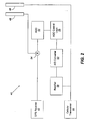
- FIG. 2 is a block diagram illustrating systems and methods for maintaining operation of a GPS receiver co-located with a cellular transceiver in accordance with a first embodiment of the present invention.
- a wireless communicator 40 includes a GPS receiver 42 co-located with a cellular transceiver 44.
- the cellular transceiver 44 includes both a transmit and a receive capability, which may be embodied as separate components as is understood by those skilled in the art.
- the cellular transceiver 44 is configured to communicate using TDMA wireless access technology. It should be understood that alternative wireless access technologies can be used without departing from the principles of the present invention.
- the communication protocol associated with the wireless access technology includes periodic intervals during which the cellular transceiver 44 is not transmitting.
- the wireless communicator 40 further includes a cellular antenna 46 and a GPS antenna 48 that may be imperfectly isolated from each other. For example, when multiple radio band antennas are co-located in the same housing, antenna isolation is typically in the range of 10dB - 15dB. Assuming that the cellular transceiver 44 transmits at a power level of 26dB and there is only 10dB - 15dB separation between the antennas 46, 48, the transmitted TDMA signal may be coupled to the input of the GPS receiver 42 at a power level of 11 dB - 16dB. This superimposed TDMA signal can interfere with the reception and decoding of the GPS signal at the GPS receiver 42.
- a TDMA frame comprises a transmit interval, a mobile assisted handoff (MAHO) interval, and a receive interval.
- the TDMA signal transmitted by the cellular transceiver 44 can be coupled to the input of the GPS receiver 42 through the GPS antenna 48, which can disrupt the reception and decoding of the GPS signal at the GPS receiver 42.
- the signal applied to the input of the GPS receiver which is a combination of the desired GPS signal and the undesired TDMA signal, generally exhibits an enhanced power level due to the addition of the TDMA signal.
- an AGC module 52 may reduce the gain applied to the signal at the input of the GPS receiver 42 through a multiplier 54.
- a MAHO interval and a receive interval are shown, for example, to follow the transmit interval in a conventional TDMA frame. While a TDMA transmitter is active during the transmit interval, the TDMA transmitter is generally inactive during the MAHO and receive intervals when the TDMA receiver is active.
- the MAHO interval is used to monitor the signal strength of the setup channels of neighboring cells to identify potential candidates for handoff should the signal strength of the voice channel in the current cell become too weak.
- the receive interval is complementary to the transmit interval to provide full duplex communication with another party.
- the cellular transceiver 44 does not transmit during either the MAHO or receive intervals, thereby ending the interference with the GPS receiver due to coupling of the TDMA signal through the GPS antenna 48.
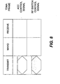
- FIG. 8 illustrates a single TDMA frame.
- the cellular transceiver 44 may transmit and receive during portions of each of a plurality of successive TDMA frames.
- each TDMA frame may include periods during which the transceiver is neither transmitting nor receiving.
- the gain applied to the signal at the input of the GPS receiver 42 through the multiplier 54 is typically reduced by the AGC module 52 due to the enhanced signal strength provided by the undesired TDMA signal. Therefore, even though the interference from the TDMA signal transmitted by the cellular transmitter 44 will have ceased at the beginning of the MAHO interval, the GPS receiver 42 may not be able to decode the GPS signal because the gain applied to the GPS signal by the AGC module 52 through the multiplier 54 is too low. The AGC module 52 will begin to raise the gain applied at the multiplier 54 as it detects the reduced signal strength of GPS signal as compared to the combination of the GPS signal and the coupled TDMA transmission signal.
- the present invention maintains operation of the GPS receiver 42 by using AGC control logic 56 that is responsive to the TDMA radio signal that is transmitted by the cellular transceiver 44. More specifically, the AGC control logic 56 monitors this transmission signal to anticipate the beginning of the transmit interval. As a result, the AGC control logic 56 identifies the beginning of the transmit interval and generates a control signal, which is applied to the AGC module 52 to preserve the gain value ( i.e., prevents the gain value from being reduced) that is applied to the input signal of the GPS receiver 42 through the multiplier 54. Thus, the GPS receiver 42 is desensitized to the effects of the TDMA signal transmitted by the cellular transceiver 44.
- the AGC control logic 56 continues to monitor the TDMA radio signal that is transmitted by the cellular transceiver 44 to determine the end of the transmit interval. During the MAHO and receive intervals (and other intervals during which the transceiver 44 does not transmit), the AGC control logic 56 ceases generation of the control signal to allow the AGC module 52 to adjust the gain applied in accordance with the strength of the GPS signal. This procedure is illustrated, for example, in FIG. 8 where the AGC control signal is driven high during the transmit interval and is driven low during the MAHO and receive intervals.
- a rectifier 58 is used to convert the TDMA radio signal to a DC value, which is then converted to digital form by an analog to digital (A/D) converter 62.
- AGC control logic 56 can then be implemented as digital logic to process the digital information output from the A/D converter 62.
- GPS reception and decoding will still be subject to interference from the TDMA signal transmitted by the cellular transceiver 44 during the transmit interval. Nevertheless, by preventing the AGC module 52 from oscillating due to the cyclical application of a TDMA interference signal during successive TDMA frames, GPS operation can be successfully maintained during the MAHO and receive intervals.
- FIG. 3A is a block diagram illustrating systems and methods for maintaining operation of a GPS receiver co-located with a cellular transceiver in accordance with a second embodiment of the present invention.
- the wireless communicator 70 illustrated in FIG. 3A is substantially similar to the wireless communicator 40 of FIG. 2 .
- RF switch control logic 72 is used that is responsive to the TDMA radio signal that is transmitted by the cellular transceiver 44. More specifically, the RF switch control logic 72 monitors this transmission signal to anticipate the beginning of the transmit interval. As a result, the RF switch control logic 56 identifies the beginning of the transmit interval and generates a control signal that causes a switch 74 to open when applied thereto. Because the switch 74 and the GPS receiver 42 are connected in series, the GPS receiver 42 is electrically isolated from the GPS antenna 48 when the switch 74 is open.
- the GPS receiver 42 and the AGC module 52 are desensitized to the effects of the TDMA signal transmitted by the cellular transceiver 44 when the switch 74 is in the open position. Complete isolation of the GPS receiver 42 may be preferred during the TDMA transmit interval particularly when the cellular transceiver 44 transmits at very high power levels.
- the RF switch control logic 72 continues to monitor the TDMA radio signal that is transmitted by the cellular transceiver 44 to determine the end of the transmit interval. During the MAHO and receive intervals, the RF switch control logic 72 ceases generation of the control signal to allow the switch 74 to close, thereby electrically reconnecting the GPS receiver 42 with the GPS antenna 48. This procedure is illustrated, for example, in FIG. 8 where the RF switch control signal is driven high during the transmit interval and is driven low during the MAHO and receive intervals.
- FIG. 3B An alternative configuration for the switch 74 of FIG. 3A is shown in FIG. 3B .
- the switch 74' is connected in parallel between the GPS antenna 48 and the GPS receiver 42 such that the GPS antenna 48 is shorted to ground when the switch 74' is closed.
- the operations of switch 74 of FIG. 3A and switch 74' of FIG. 3B are opposite. That is, the GPS receiver 42 and the AGC module 52 are desensitized by causing the switch 74' to close through a control signal generated by the RF switch control logic 72 in FIG. 3B . Conversely, the GPS receiver 42 and the AGC module 52 are desensitized by causing the switch 74 to open through a control signal generated by the RF switch control logic 72 in FIG. 3A
- FIG. 4 is a block diagram illustrating systems and methods for maintaining operation of a GPS receiver co-located with a cellular transceiver in accordance with a third embodiment of the present invention.
- the wireless communicator 80 illustrated in FIG. 4 uses both the AGC control logic 56 of FIG. 2 and the RF switch control logic 72 of FIGS. 3A-3B . Because the response times for operating the switch 74 and the AGC module 52 may differ, and the response time of the AGC control logic 56 and the RF switch control logic 72 may also differ, this embodiment ensures that the GPS receiver 42 and the AGC module 52 are desensitized to the effects of the transmitted TDMA signal via whichever of the two means is faster. It should also be understood that while the switch 74 in FIG. 4 is configured in series with the GPS receiver 42 as discussed hereinbefore with reference to FIG. 3A , the switch 74 may alternatively be configured between the GPS antenna 48 and ground as discussed and illustrated hereinbefore with reference to FIG. 3B .
- FIG. 5 is a block diagram illustrating systems and methods for maintaining operation of a GPS receiver co-located with a cellular transceiver in accordance with a fourth embodiment of the present invention.
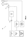
- the wireless communicator 90 is based on a similar architecture as the embodiments of FIGS. 2 , 3A , 3B , and 4 . By contrast, however, the wireless communicator 90 does not include AGC control logic 56 nor RF switch control logic 72. Operation of the AGC module 52 is maintained through use of a processor 92, which communicates with a computer readable storage medium or memory 94.
- the present invention can therefore take the form of a computer program product on a computer-usable or computer-readable storage medium having computer-usable or computer-readable program code means embodied in the medium for use by or in connection with an instruction execution system.
- a computer-usable or computer-readable medium can be any means that can contain, store, communicate, propagate, or transport the program for use by or in connection with the instruction execution system, apparatus, or device.
- the computer-usable or computer-readable medium can be, for example but not limited to, an electronic, magnetic, optical, electromagnetic, infrared, or semiconductor system, apparatus, device, or propagation medium. More specific examples (a nonexhaustive list) of the computer-readable medium would include the following: an electrical connection having one or more wires, a portable computer diskette, a random access memory (RAM), a read-only memory (ROM), an erasable programmable read-only memory (EPROM or Flash memory), an optical fiber, and a portable compact disc read-only memory (CD-ROM).
- RAM random access memory
- ROM read-only memory
- EPROM or Flash memory erasable programmable read-only memory
- CD-ROM portable compact disc read-only memory
- the computer-usable or computer-readable medium could even be paper or another suitable medium upon which the program is printed, as the program can be electronically captured, via, for instance, optical scanning of the paper or other medium, then compiled, interpreted, or otherwise processed in a suitable manner if necessary, and then stored in a computer memory.
- the memory 94 includes a communication protocol program 96 that controls operations of the cellular transceiver 44 in implementing a communication session.
- the communication protocol corresponds to a particular wireless access technology being used, such as TDMA.
- the communication protocol program 96 is responsive to call setup information received by the cellular transceiver 44 that, in the case of TDMA, identifies particular time slots or intervals in each TDMA frame during which the transceiver 44 can transmit.
- the communication protocol program 96 can thus use this knowledge of the intervals or time slots that will be used for transmission by the cellular transceiver in the TDMA frames to generate a control signal from the processor 92 that identifies or corresponds to these transmission intervals. This control signal can then be applied to the AGC module 52 to preserve the gain value ( i.e. , prevent the gain value from being reduced) as discussed hereinbefore.
- FIG. 6 is a block diagram illustrating systems and methods for maintaining operation of a GPS receiver co-located with a cellular transceiver in accordance with a fifth embodiment of the present invention.
- the wireless communicator 110 illustrated in FIG. 6 is substantially similar to the wireless communicator 90 of FIG. 5 .
- the control signal is applied to a switch 74 that is configured in series with the GPS receiver 42.
- the control signal causes the switch 74 to open thereby electrically isolating the GPS receiver 42 from the GPS antenna 48.
- the switch 74 in FIG. 6 is configured in series with the GPS receiver 42, the switch 74 may alternatively be configured between the GPS antenna 48 and ground as discussed and illustrated hereinbefore with reference to FIG. 3B .
- FIG. 7 is a block diagram illustrating systems and methods for maintaining operation of a GPS receiver co-located with a cellular transceiver in accordance with a sixth embodiment of the present invention.
- the wireless communicator 110 illustrated in FIG. 4 uses two control signals--one control signal is provided by the processor 92 to the AGC module as discussed hereinabove with reference to FIG. 5 and a second control signal is provided by the processor 92 to the switch 74 as discussed hereinabove with reference to FIG. 6 . Because the response times for operating the switch 74 and the AGC module 52 may differ, this embodiment ensures that the GPS receiver 42 and the AGC module 52 are desensitized to the effects of the transmitted TDMA signal via whichever of the two means is faster.
- the switch 74 in FIG. 7 is configured in series with the GPS receiver 42, the switch 74 may alternatively be configured between the GPS antenna 48 and ground as discussed and illustrated hereinbefore with reference to FIG. 3B .
- Bluetooth is a universal radio interface in the 2.45 GHz frequency band that enables portable electronic devices to connect and communicate wirelessly via short-range, ad hoc networks. Bluetooth technology is generally targeted towards the elimination of wires, cables, and connectors between such devices and systems as cordless or mobile phones, modems, headsets, PDAs, computers, printers, projectors, and local area networks.
Landscapes
- Engineering & Computer Science (AREA)
- Computer Networks & Wireless Communication (AREA)
- Signal Processing (AREA)
- Remote Sensing (AREA)
- Radar, Positioning & Navigation (AREA)
- Physics & Mathematics (AREA)
- General Physics & Mathematics (AREA)
- Transceivers (AREA)
- Mobile Radio Communication Systems (AREA)
- Noise Elimination (AREA)
- Position Fixing By Use Of Radio Waves (AREA)
- Transmitters (AREA)
- Paper (AREA)
Abstract
Description
- The present invention relates generally to the field of communication, and, more particularly, to communication devices having a co-located transmitter and receiver in which the transmitter can interfere with the operation of the receiver.
- Wireless communicators are being used in ever increasing numbers for voice calls, data calls, facsimile transfer, Internet access, paging, and other personal organization features such as calendar management or even travel directions via the Global Positioning System (GPS). GPS is a worldwide navigation system that is based on a constellation of satellites, which are used as reference points to calculate positions on earth. More specifically, GPS uses a technique known as "triangulation" in which the GPS receiver determines the distance to particular satellites using the travel time of the GPS signals transmitted by those satellites. In addition to determining the distance to a transmitting satellite, the receiver may also obtain information from a GPS signal that indicates the position of the transmitting satellite in space. Finally, the receiver may correct for delay that a GPS signal can experience in traveling through the atmosphere.
- As used herein, the term "wireless communicator" can include a cellular radiotelephone with a multi-line display, a Personal Communications System (PCS) terminal that may combine a cellular radiotelephone with data processing, facsimile and data communications capabilities, a Personal Digital Assistant (PDA) that can include a radiotelephone, pager, Internet/intranet access, Web browser, organizer, calendar and/or a GPS receiver, and conventional laptop and/or palmtop receivers that include radiotelephone transceivers. Wireless communicators also may be referred to as "pervasive computing" devices.
- Wireless communicators that include both a cellular radiotelephone and a GPS receiver, for example, may be susceptible to interference between the cellular phone transmitter circuitry and the GPS receiver circuitry. With reference to
FIG. 1 , awireless communicator 22 is illustrated in which aGPS receiver 24 and acellular transceiver 26 are co-located. Because thewireless communicator 22 may be relatively small and have minimal separation between theGPS antenna 28 and thecellular antenna 32, it is not uncommon for radio frequency (RF) signals transmitted from thecellular transceiver 26 to couple from thecellular antenna 32 to theGPS antenna 28. As a result, this unwanted interference from thecellular transceiver 26 may inhibit operation of theGPS receiver 24. - In addition to interfering with the reception and decoding of a GPS signal while the
cellular transceiver 26 is transmitting, operation of theGPS receiver 24 may also be disrupted while thecellular transceiver 26 is idle or is in a receive mode. As shown inFIG. 1 , an automatic gain control (AGC)module 34 is typically used to adjust the gain of the signal received through theGPS antenna 28 to a power level suitable for processing by theGPS receiver 24. The coupling of an RF signal from thecellular antenna 32 to theGPS antenna 28, however, generally increases the strength of the signal applied to the input of theGPS receiver 24. Therefore, theAGC module 34 may reduce the gain applied at amultiplier 36 when thecellular transceiver 26 transmits. When thecellular transceiver 26 transitions to an idle mode or a receive mode for the particular communication protocol that it is implementing, the gain applied by theAGC module 34 may be insufficient to provide a suitable signal power level at the input of theGPS receiver 24. TheAGC module 34 may thus increase the gain in response to the lower power level of the signal from theGPS antenna 28, but thecellular transceiver 26 may eventually transition back into the transmit mode, thereby causing the cycle to repeat. - Thus, it can be difficult to maintain operation of the
GPS receiver 24 when it is co-located with acellular transceiver 26. When thecellular transceiver 26 is transmitting, the transmitted signal can interfere with the reception and decoding of a GPS signal by theGPS receiver 24. When thecellular transceiver 26 is idle or is receiving a cellular signal, the GPS signal received at theGPS receiver 24 may be too weak to decode because the gain applied by theAGC module 34 has been reduced from its normal operating value due to the prior interference from the signal transmitted by thecellular transceiver 26. - Consequently, a need exists for improved communication devices in which the operation of a receiver can be maintained notwithstanding interference from a co-located transmitter. Document
WO 99 36795 - It is therefore an object of the present invention to provide improved communication devices in which a receiver is co-located with a transmitter and is susceptible to interference therefrom.
- It is another object of the present invention to provide systems and methods that can be used to maintain operation of a receiver in a communication device that is subject to interference from a co-located transmitter during periodic transmission intervals.
- These and other objects, advantages, and features of the present invention may be provided by systems and methods according to
independent claims - In accordance with the present invention, control logic is used to monitor a signal generated by the transmitter. By monitoring the aforementioned signal, the control logic is able to anticipate the beginning of the transmission intervals and generate a control signal that identifies or corresponds to the intervals in which the transmitter is active or transmitting. This control signal is then supplied to an automatic gain control module to maintain the gain applied at the input of a second receiver at or above its current-level. Advantageously, if the signal transmitted by the transmitter is coupled to the second receiver thereby causing interference, then the automatic gain control module will not reduce the gain applied due to the enhanced signal strength resulting from the interference. When a transmission interval completes, the gain provided by the automatic gain control module is therefore at a proper level for normal or steady state operation.
- In accordance with another illustrative embodiment of the invention, control logic is used to anticipate the beginning of a transmission interval; however, the control signal generated in response thereto is used to drive a switch that electrically isolates the second receiver from an antenna associated therewith during the transmission interval.
- In accordance with still another illustrative embodiment of the invention, a communication protocol (e.g., a protocol based on time division multiple access (TDMA) technology) program is used that anticipates the active or transmission intervals of the transmitter and generates a control signal via a processor to desensitize the receiver during these intervals.
- The present invention can allow, for example, a GPS receiver, co-located in a cellular phone terminal, to operate almost simultaneously with a TDMA transmitter. Heretofore, in an application where there is minimal antenna isolation between the GPS receiver antenna and the cellular phone antenna, operation of the GPS receiver may be severely hampered due to disruption of the gain applied by an automatic gain control module at the input of the GPS receiver.
- Other features of the present invention will be more readily understood from the following detailed description of specific embodiments thereof when read in conjunction with the accompanying drawings, in which:
-
FIG. 1 is a block diagram of a conventional wireless communicator including a GPS receiver co-located with a cellular transceiver; -
FIG. 2 is a block diagram illustrating an exemplary system for maintaining operation of a GPS receiver co-located with a cellular transceiver according to a first embodiment of the present invention; -
FIG. 3A is a block diagram illustrating an exemplary system for maintaining operation of a GPS receiver co-located with a cellular transceiver according to a second embodiment of the present invention; -
FIG. 3B is a block diagram illustrating an alternative configuration for the switch ofFIG. 3A ; -
FIG. 4 is a block diagram illustrating an exemplary system for maintaining operation of a GPS receiver co-located with a cellular transceiver according to a third embodiment of the present invention that combines aspects of theFIG. 2 andFIG. 3A embodiments; -
FIG. 5 is a block diagram illustrating an exemplary system for maintaining operation of a GPS receiver co-located with a cellular transceiver according to a fourth embodiment of the present invention; -
FIG. 6 is a block diagram illustrating an exemplary system for maintaining operation of a GPS receiver co-located with a cellular transceiver according to a fifth embodiment of the present invention; -
FIG. 7 is a block diagram illustrating an exemplary system for maintaining operation of a GPS receiver co-located with a cellular transceiver according to a third embodiment of the present invention that combines aspects of theFIG. 5 andFIG. 6 embodiments; and -
FIG. 8 illustrates signal-timing diagrams associated with the embodiments ofFIGS. 2-7 . - While the invention is susceptible to various modifications and alternative forms, specific embodiments thereof are shown by way of example in the drawings and will herein be described in detail. It should be understood, however, that there is no intent to limit the invention to the particular forms disclosed, but on the contrary, the invention is to cover all modifications, equivalents, and alternatives falling within the scope of the invention as defined by the claims. Like reference numbers signify like elements throughout the description of the figures.
- For purposes of illustration and in no way limited thereto, systems and methods for maintaining operation of a receiver co-located with a transmitter will be discussed hereafter in connection with a wireless communicator comprising a GPS receiver and a cellular transceiver using TDMA technology (e.g., the Telecommunication Industry Association (TIA)/ Electronic Industries Association (EIA) 136 or digital advanced mobile phone service (DAMPS) standard). It should be understood, therefore, that the systems and methods according to the present invention can be applied generally to communication devices in which a receiver co-located with a transmitter is susceptible to interference from a signal transmitted by the transmitter.
-
FIG. 2 is a block diagram illustrating systems and methods for maintaining operation of a GPS receiver co-located with a cellular transceiver in accordance with a first embodiment of the present invention. As shown inFIG. 2 , awireless communicator 40 includes aGPS receiver 42 co-located with acellular transceiver 44. Thecellular transceiver 44 includes both a transmit and a receive capability, which may be embodied as separate components as is understood by those skilled in the art. Thecellular transceiver 44 is configured to communicate using TDMA wireless access technology. It should be understood that alternative wireless access technologies can be used without departing from the principles of the present invention. Preferably, the communication protocol associated with the wireless access technology includes periodic intervals during which thecellular transceiver 44 is not transmitting. - The
wireless communicator 40 further includes acellular antenna 46 and aGPS antenna 48 that may be imperfectly isolated from each other. For example, when multiple radio band antennas are co-located in the same housing, antenna isolation is typically in the range of 10dB - 15dB. Assuming that thecellular transceiver 44 transmits at a power level of 26dB and there is only 10dB - 15dB separation between theantennas GPS receiver 42 at a power level of 11 dB - 16dB. This superimposed TDMA signal can interfere with the reception and decoding of the GPS signal at theGPS receiver 42. - It may be helpful to briefly review the nature of the interference with GPS signal reception that may be caused by the
cellular transmitter 44 and was discussed previously hereinbefore. With reference toFIG. 8 , a TDMA frame comprises a transmit interval, a mobile assisted handoff (MAHO) interval, and a receive interval. During the transmit interval, the TDMA signal transmitted by thecellular transceiver 44 can be coupled to the input of theGPS receiver 42 through theGPS antenna 48, which can disrupt the reception and decoding of the GPS signal at theGPS receiver 42. In addition, however, the signal applied to the input of the GPS receiver, which is a combination of the desired GPS signal and the undesired TDMA signal, generally exhibits an enhanced power level due to the addition of the TDMA signal. As a result, anAGC module 52 may reduce the gain applied to the signal at the input of theGPS receiver 42 through amultiplier 54. - Referring again to
FIG. 8 , a MAHO interval and a receive interval are shown, for example, to follow the transmit interval in a conventional TDMA frame. While a TDMA transmitter is active during the transmit interval, the TDMA transmitter is generally inactive during the MAHO and receive intervals when the TDMA receiver is active. The MAHO interval is used to monitor the signal strength of the setup channels of neighboring cells to identify potential candidates for handoff should the signal strength of the voice channel in the current cell become too weak. The receive interval is complementary to the transmit interval to provide full duplex communication with another party. Thus, thecellular transceiver 44 does not transmit during either the MAHO or receive intervals, thereby ending the interference with the GPS receiver due to coupling of the TDMA signal through theGPS antenna 48. Nevertheless, the residual effect of the TDMA signal transmitted from thecellular transceiver 44 may still remain. Moreover,FIG. 8 illustrates a single TDMA frame. Thecellular transceiver 44 may transmit and receive during portions of each of a plurality of successive TDMA frames. Furthermore, each TDMA frame may include periods during which the transceiver is neither transmitting nor receiving. - At the end of the transmit interval, the gain applied to the signal at the input of the
GPS receiver 42 through themultiplier 54 is typically reduced by theAGC module 52 due to the enhanced signal strength provided by the undesired TDMA signal. Therefore, even though the interference from the TDMA signal transmitted by thecellular transmitter 44 will have ceased at the beginning of the MAHO interval, theGPS receiver 42 may not be able to decode the GPS signal because the gain applied to the GPS signal by theAGC module 52 through themultiplier 54 is too low. TheAGC module 52 will begin to raise the gain applied at themultiplier 54 as it detects the reduced signal strength of GPS signal as compared to the combination of the GPS signal and the coupled TDMA transmission signal. Nevertheless, there will be some latency or delay before a suitable gain is applied at themultiplier 54, which may disrupt GPS reception and decoding for some period during the MAHO interval and possibly the receive interval (or during any interval without transmission by the transceiver 44) following an interval with transmission. - It can be seen, therefore, that successful GPS reception and decoding can be achieved during the MAHO and receive intervals (or any other intervals without transmission) after the
AGC module 52 has detected the absence of the coupled TDMA signal from thecellular transceiver 44 and adjusted the gain accordingly. The interval during which GPS operation is feasible is thus dependent upon the sensitivity and responsiveness of theAGC module 52 and the length of the MAHO and receive intervals of the TDMA frame. Unfortunately, in some circumstances the gain applied by theAGC module 52 may be increased to a level sufficient to support GPS reception and decoding just prior to the beginning of the transmit interval of the next TDMA frame, which may not be long enough to provide practical GPS service. - The present invention maintains operation of the
GPS receiver 42 by usingAGC control logic 56 that is responsive to the TDMA radio signal that is transmitted by thecellular transceiver 44. More specifically, theAGC control logic 56 monitors this transmission signal to anticipate the beginning of the transmit interval. As a result, theAGC control logic 56 identifies the beginning of the transmit interval and generates a control signal, which is applied to theAGC module 52 to preserve the gain value (i.e., prevents the gain value from being reduced) that is applied to the input signal of theGPS receiver 42 through themultiplier 54. Thus, theGPS receiver 42 is desensitized to the effects of the TDMA signal transmitted by thecellular transceiver 44. TheAGC control logic 56 continues to monitor the TDMA radio signal that is transmitted by thecellular transceiver 44 to determine the end of the transmit interval. During the MAHO and receive intervals (and other intervals during which thetransceiver 44 does not transmit), theAGC control logic 56 ceases generation of the control signal to allow theAGC module 52 to adjust the gain applied in accordance with the strength of the GPS signal. This procedure is illustrated, for example, inFIG. 8 where the AGC control signal is driven high during the transmit interval and is driven low during the MAHO and receive intervals. - Preferably, a
rectifier 58 is used to convert the TDMA radio signal to a DC value, which is then converted to digital form by an analog to digital (A/D)converter 62.AGC control logic 56 can then be implemented as digital logic to process the digital information output from the A/D converter 62. - Note that GPS reception and decoding will still be subject to interference from the TDMA signal transmitted by the
cellular transceiver 44 during the transmit interval. Nevertheless, by preventing theAGC module 52 from oscillating due to the cyclical application of a TDMA interference signal during successive TDMA frames, GPS operation can be successfully maintained during the MAHO and receive intervals. -
FIG. 3A is a block diagram illustrating systems and methods for maintaining operation of a GPS receiver co-located with a cellular transceiver in accordance with a second embodiment of the present invention. Thewireless communicator 70 illustrated inFIG. 3A is substantially similar to thewireless communicator 40 ofFIG. 2 . Instead of usingAGC control logic 56, however, RFswitch control logic 72 is used that is responsive to the TDMA radio signal that is transmitted by thecellular transceiver 44. More specifically, the RFswitch control logic 72 monitors this transmission signal to anticipate the beginning of the transmit interval. As a result, the RFswitch control logic 56 identifies the beginning of the transmit interval and generates a control signal that causes aswitch 74 to open when applied thereto. Because theswitch 74 and theGPS receiver 42 are connected in series, theGPS receiver 42 is electrically isolated from theGPS antenna 48 when theswitch 74 is open. - Thus, the
GPS receiver 42 and theAGC module 52 are desensitized to the effects of the TDMA signal transmitted by thecellular transceiver 44 when theswitch 74 is in the open position. Complete isolation of theGPS receiver 42 may be preferred during the TDMA transmit interval particularly when thecellular transceiver 44 transmits at very high power levels. The RFswitch control logic 72 continues to monitor the TDMA radio signal that is transmitted by thecellular transceiver 44 to determine the end of the transmit interval. During the MAHO and receive intervals, the RFswitch control logic 72 ceases generation of the control signal to allow theswitch 74 to close, thereby electrically reconnecting theGPS receiver 42 with theGPS antenna 48. This procedure is illustrated, for example, inFIG. 8 where the RF switch control signal is driven high during the transmit interval and is driven low during the MAHO and receive intervals. - An alternative configuration for the
switch 74 ofFIG. 3A is shown inFIG. 3B . In theFIG. 3B embodiment, the switch 74' is connected in parallel between theGPS antenna 48 and theGPS receiver 42 such that theGPS antenna 48 is shorted to ground when the switch 74' is closed. Note that the operations ofswitch 74 ofFIG. 3A and switch 74' ofFIG. 3B are opposite. That is, theGPS receiver 42 and theAGC module 52 are desensitized by causing the switch 74' to close through a control signal generated by the RFswitch control logic 72 inFIG. 3B . Conversely, theGPS receiver 42 and theAGC module 52 are desensitized by causing theswitch 74 to open through a control signal generated by the RFswitch control logic 72 inFIG. 3A -
FIG. 4 is a block diagram illustrating systems and methods for maintaining operation of a GPS receiver co-located with a cellular transceiver in accordance with a third embodiment of the present invention. Thewireless communicator 80 illustrated inFIG. 4 uses both theAGC control logic 56 ofFIG. 2 and the RFswitch control logic 72 ofFIGS. 3A-3B . Because the response times for operating theswitch 74 and theAGC module 52 may differ, and the response time of theAGC control logic 56 and the RFswitch control logic 72 may also differ, this embodiment ensures that theGPS receiver 42 and theAGC module 52 are desensitized to the effects of the transmitted TDMA signal via whichever of the two means is faster. It should also be understood that while theswitch 74 inFIG. 4 is configured in series with theGPS receiver 42 as discussed hereinbefore with reference toFIG. 3A , theswitch 74 may alternatively be configured between theGPS antenna 48 and ground as discussed and illustrated hereinbefore with reference toFIG. 3B . -
FIG. 5 is a block diagram illustrating systems and methods for maintaining operation of a GPS receiver co-located with a cellular transceiver in accordance with a fourth embodiment of the present invention. Thewireless communicator 90 is based on a similar architecture as the embodiments ofFIGS. 2 ,3A ,3B , and4 . By contrast, however, thewireless communicator 90 does not includeAGC control logic 56 nor RFswitch control logic 72. Operation of theAGC module 52 is maintained through use of aprocessor 92, which communicates with a computer readable storage medium ormemory 94. The present invention can therefore take the form of a computer program product on a computer-usable or computer-readable storage medium having computer-usable or computer-readable program code means embodied in the medium for use by or in connection with an instruction execution system. In the context of this document, a computer-usable or computer-readable medium can be any means that can contain, store, communicate, propagate, or transport the program for use by or in connection with the instruction execution system, apparatus, or device. - The computer-usable or computer-readable medium can be, for example but not limited to, an electronic, magnetic, optical, electromagnetic, infrared, or semiconductor system, apparatus, device, or propagation medium. More specific examples (a nonexhaustive list) of the computer-readable medium would include the following: an electrical connection having one or more wires, a portable computer diskette, a random access memory (RAM), a read-only memory (ROM), an erasable programmable read-only memory (EPROM or Flash memory), an optical fiber, and a portable compact disc read-only memory (CD-ROM). Note that the computer-usable or computer-readable medium could even be paper or another suitable medium upon which the program is printed, as the program can be electronically captured, via, for instance, optical scanning of the paper or other medium, then compiled, interpreted, or otherwise processed in a suitable manner if necessary, and then stored in a computer memory.
- The
memory 94 includes acommunication protocol program 96 that controls operations of thecellular transceiver 44 in implementing a communication session. Recall that the communication protocol corresponds to a particular wireless access technology being used, such as TDMA. Thus, thecommunication protocol program 96 is responsive to call setup information received by thecellular transceiver 44 that, in the case of TDMA, identifies particular time slots or intervals in each TDMA frame during which thetransceiver 44 can transmit. - The
communication protocol program 96 can thus use this knowledge of the intervals or time slots that will be used for transmission by the cellular transceiver in the TDMA frames to generate a control signal from theprocessor 92 that identifies or corresponds to these transmission intervals. This control signal can then be applied to theAGC module 52 to preserve the gain value (i.e., prevent the gain value from being reduced) as discussed hereinbefore. -
FIG. 6 is a block diagram illustrating systems and methods for maintaining operation of a GPS receiver co-located with a cellular transceiver in accordance with a fifth embodiment of the present invention. Thewireless communicator 110 illustrated inFIG. 6 is substantially similar to thewireless communicator 90 ofFIG. 5 . Instead of using the control signal generated from theprocessor 92 to preserve the gain applied by theAGC module 52; however, the control signal is applied to aswitch 74 that is configured in series with theGPS receiver 42. During a transmission interval, the control signal causes theswitch 74 to open thereby electrically isolating theGPS receiver 42 from theGPS antenna 48. It should also be understood that while theswitch 74 inFIG. 6 is configured in series with theGPS receiver 42, theswitch 74 may alternatively be configured between theGPS antenna 48 and ground as discussed and illustrated hereinbefore with reference toFIG. 3B . - Lastly,
FIG. 7 is a block diagram illustrating systems and methods for maintaining operation of a GPS receiver co-located with a cellular transceiver in accordance with a sixth embodiment of the present invention. Thewireless communicator 110 illustrated inFIG. 4 uses two control signals--one control signal is provided by theprocessor 92 to the AGC module as discussed hereinabove with reference toFIG. 5 and a second control signal is provided by theprocessor 92 to theswitch 74 as discussed hereinabove with reference toFIG. 6 . Because the response times for operating theswitch 74 and theAGC module 52 may differ, this embodiment ensures that theGPS receiver 42 and theAGC module 52 are desensitized to the effects of the transmitted TDMA signal via whichever of the two means is faster. Again, it should be understood that while theswitch 74 inFIG. 7 is configured in series with theGPS receiver 42, theswitch 74 may alternatively be configured between theGPS antenna 48 and ground as discussed and illustrated hereinbefore with reference toFIG. 3B . - The principles of the present invention have been illustrated herein as they are applied to a
GPS receiver 42. It should be understood, however, that the principles are equally applicable to alternative receiver types that may be susceptible to interference from a signal generated by a co-located transmitter and could benefit from desensitization during transmission intervals. One such example is a Bluetooth receiver. Bluetooth is a universal radio interface in the 2.45 GHz frequency band that enables portable electronic devices to connect and communicate wirelessly via short-range, ad hoc networks. Bluetooth technology is generally targeted towards the elimination of wires, cables, and connectors between such devices and systems as cordless or mobile phones, modems, headsets, PDAs, computers, printers, projectors, and local area networks. More information on the Bluetooth interface can be found in an article authored by Jaap Haartsen entitled "Bluetooth--The universal radio interface for ad hoc, wireless connectivity," Ericsson Review, No. 3, 1998, which is hereby incorporated herein by reference. - In concluding the detailed description, it should be noted that many variations and modifications can be made to the preferred embodiments without substantially departing from the principles of the present invention. All such variations and modifications are intended to be included herein within the scope of the present invention, as set forth in the following claims.
Claims (17)
- A system (40; 70; 80; 90; 100; 110) for maintaining operation of a communication device comprising:a transmitter (44) that implements a communication protocol having active and inactive transmission intervals; anda receiver (42) that is susceptible to interference from the transmitter (44) during active transmission intervals; characterized in that the system further comprisescontrol logic (72; 92, 94, 96) that anticipates the active transmission intervals by monitoring the transmission signals and identifying the active transmission intervals, and generates a control signal to desensitize the receiver (42) during the active transmission intervals.
- A system as recited in Claim 1, further comprising:a rectifier (58), responsive to the transmitter (44), that generates a direct current signal; andan analog to digital converter (62) that generates a digital signal in response to the direct current signal and provides the digital signal to the control logic (72).
- A system as recited in Claim 1, wherein the control logic comprises:a computer readable storage medium (94) having computer readable program code means (96) that anticipate the active transmission intervals; anda processor (92), responsive to the computer readable program code means (96), that generates the control signal.
- A system as recited in Claim 1 or 2, further comprising:an automatic gain control (56), responsive to the control signal, that prevents a gain applied at an input of the receiver (42) from being reduced during the active transmission intervals.
- A system as recited in any of Claims 1-4, further comprising:a switch (74), responsive to the control signal that electrically isolates the receiver (42) from the transmitter (44).
- A system as recited in Claim 5, wherein the switch (74) is connected in series between the receiver (42) and an antenna (48).
- A system as recited in Claim 5, wherein the switch (74) is connected between an antenna (48) that is electrically connected to the receiver (42) and ground.
- A system as recited in any of claims 1-7, wherein the receiver is a global positioning system (GPS) receiver (42).
- A system as recited in any of Claims 1-7, wherein the receiver is a Bluetooth receiver.
- A system as recited in any of Claims 1-9, wherein the communication protocol is based on TDMA wireless access technology.
- A method of maintaining operation of a communication device (40; 70; 80; 90; 100; 110), comprising the steps of:providing a transmitter (44) that implements a communication protocol having active and inactive transmission intervals;providing a receiver (42) that is susceptible to interference from the transmitter (44) during active transmission intervals; characterized in that the method further comprisesanticipating the active transmission intervals by monitoring the transmission signals and identifying the active transmission intervals; anddesensitizing, responsive to the anticipating step, the receiver (42).
- A method as recited in Claim 11, wherein the desensitizing step comprises:preventing a gain applied at an input of the receiver (42) from being reduced.
- A method as recited in Claim 11 or 12, wherein the desensitizing step comprises:electrically isolating the receiver (42) from the transmitter (44).
- A method as recited in Claim 13, wherein the isolating step comprises:disconnecting the receiver (42) from an antenna (48) electrically connected thereto.
- A method as recited in Claim 13, wherein the isolating step comprises:grounding an antenna (48) electrically connected to the receiver (42).
- A method as recited in any of Claims 11-15, wherein the anticipating step comprises:converting an analog signal generated by the transmitter (44) to a digital signal; andgenerating a control signal in response to the digital signal that identifies the active transmission intervals.
- A method as recited in any of Claims 11-16, wherein the communication protocol is based on TDMA wireless access technology.
Applications Claiming Priority (3)
| Application Number | Priority Date | Filing Date | Title |
|---|---|---|---|
| US353238 | 1999-07-14 | ||
| US09/353,238 US6442375B1 (en) | 1999-07-14 | 1999-07-14 | Systems and methods for maintaining operation of a receiver co-located with a transmitter and susceptible to interference therefrom by desensitization of the receiver |
| PCT/US2000/014421 WO2001006669A1 (en) | 1999-07-14 | 2000-05-25 | Systems and methods for maintaining operation of a receiver co-located with a transmitter and susceptible to interference therefrom by desensitization of the receiver |
Publications (2)
| Publication Number | Publication Date |
|---|---|
| EP1201038A1 EP1201038A1 (en) | 2002-05-02 |
| EP1201038B1 true EP1201038B1 (en) | 2009-01-28 |
Family
ID=23388288
Family Applications (1)
| Application Number | Title | Priority Date | Filing Date |
|---|---|---|---|
| EP00936295A Expired - Lifetime EP1201038B1 (en) | 1999-07-14 | 2000-05-25 | System and method to avoid interference between co-located transmitter and receiver |
Country Status (12)
| Country | Link |
|---|---|
| US (1) | US6442375B1 (en) |
| EP (1) | EP1201038B1 (en) |
| JP (1) | JP4553538B2 (en) |
| CN (1) | CN100468978C (en) |
| AR (1) | AR028152A1 (en) |
| AT (1) | ATE422117T1 (en) |
| AU (1) | AU5163100A (en) |
| CO (1) | CO5310566A1 (en) |
| DE (1) | DE60041494D1 (en) |
| ES (1) | ES2319854T3 (en) |
| MY (1) | MY126035A (en) |
| WO (1) | WO2001006669A1 (en) |
Families Citing this family (77)
| Publication number | Priority date | Publication date | Assignee | Title |
|---|---|---|---|---|
| FI107493B (en) * | 1999-06-07 | 2001-08-15 | Nokia Mobile Phones Ltd | A data transmission adapter and a method of data transfer |
| EP1079533B1 (en) * | 1999-08-24 | 2004-12-22 | Telefonaktiebolaget LM Ericsson (publ) | Parallel operation of devices using multiple communication standards |
| US20030069996A1 (en) * | 1999-08-30 | 2003-04-10 | William M. Parrott | Infrared to radio frequency adapter and method for using the same |
| EP1113684A1 (en) * | 1999-12-29 | 2001-07-04 | Koninklijke Philips Electronics N.V. | System, device and method of simultaneously connecting to two TDMA transmission systems |
| JP4292442B2 (en) * | 2000-01-31 | 2009-07-08 | ソニー株式会社 | Global positioning system receiver and portable radio terminal |
| US6694150B1 (en) * | 2000-02-12 | 2004-02-17 | Qualcomm, Incorporated | Multiple band wireless telephone with multiple antennas |
| JP2001236138A (en) * | 2000-02-22 | 2001-08-31 | Sony Corp | Communication terminal device |
| GB0011547D0 (en) * | 2000-05-12 | 2000-06-28 | Esselte Nv | A printer |
| FI110296B (en) * | 2000-05-26 | 2002-12-31 | Nokia Corp | Hands free feature |
| DE20009885U1 (en) * | 2000-06-02 | 2001-10-18 | SCM Microsystems GmbH, 85276 Pfaffenhofen | Accumulator with reading device |
| US6961019B1 (en) * | 2000-08-10 | 2005-11-01 | Sirf Technology, Inc. | Method and apparatus for reducing GPS receiver jamming during transmission in a wireless receiver |
| AU2002243279A1 (en) | 2000-11-01 | 2002-06-18 | Flexiworld Technologies, Inc. | Controller and manager for device-to-device pervasive digital output |
| US10915296B2 (en) | 2000-11-01 | 2021-02-09 | Flexiworld Technologies, Inc. | Information apparatus that includes a touch sensitive screen interface for managing or replying to e-mails |
| US11204729B2 (en) | 2000-11-01 | 2021-12-21 | Flexiworld Technologies, Inc. | Internet based digital content services for pervasively providing protected digital content to smart devices based on having subscribed to the digital content service |
| US10860290B2 (en) | 2000-11-01 | 2020-12-08 | Flexiworld Technologies, Inc. | Mobile information apparatuses that include a digital camera, a touch sensitive screen interface, support for voice activated commands, and a wireless communication chip or chipset supporting IEEE 802.11 |
| US6831911B1 (en) * | 2000-11-18 | 2004-12-14 | Ashvattha Semiconductor Inc. | System and method for receiving and processing GPS and wireless signals |
| US7318086B2 (en) | 2000-11-20 | 2008-01-08 | Flexiworld Technologies, Inc. | System for mobile and pervasive output |
| FI20002881A7 (en) * | 2000-12-29 | 2002-06-30 | Nokia Corp | Arrangement and method for reducing radio transmitter losses |
| US20020097418A1 (en) | 2001-01-19 | 2002-07-25 | Chang William Ho | Raster image processor and processing method for universal data output |
| JP2002291019A (en) * | 2001-03-23 | 2002-10-04 | Japan Radio Co Ltd | Mobile data communication device |
| FI113990B (en) * | 2001-04-27 | 2004-07-15 | Nokia Corp | Procedure for reducing interference in a receiver and electronic device |
| US6799050B1 (en) | 2001-06-04 | 2004-09-28 | Snaptrack, Inc. | Reducing cross-interference in a combined GPS receiver and communication system |
| US6892076B2 (en) | 2002-06-05 | 2005-05-10 | Nokia Corporation | Digital video broadcast-terrestrial (DVB-T) receiver interoperable with a GSM transmitter in a non-interfering manner using classmark change procedure |
| EP1947470A3 (en) * | 2002-06-20 | 2011-09-28 | Snaptrack Inc. | Reducing cross-interference in a combined GPS receiver and communication system |
| US20040043745A1 (en) * | 2002-08-30 | 2004-03-04 | Richard Najarian | Integrated GPS receiver architecture |
| US7197089B2 (en) * | 2002-08-30 | 2007-03-27 | Rf Micro Devices, Inc. | Frequency plan for GPS receiver |
| US7099406B2 (en) * | 2002-08-30 | 2006-08-29 | Rf Micro Devices, Inc. | Alias sampling for IF-to-baseband conversion in a GPS receiver |
| US6825802B2 (en) * | 2002-11-18 | 2004-11-30 | Andreas Warloe | Avoiding interference to a GPS receiver from wireless transmissions by time multiplexing GPS reception |
| US20040095272A1 (en) * | 2002-11-18 | 2004-05-20 | Rf Micro Devices, Inc. | Saving power in a GPS receiver by controlling domain clocking |
| US6806827B2 (en) * | 2002-11-18 | 2004-10-19 | Rf Micro Devices, Inc. | Using FFT engines to process decorrelated GPS signals to establish frequencies of received signals |
| US6778135B2 (en) * | 2002-11-18 | 2004-08-17 | Rf Micro Devices, Inc. | GPS Receiver |
| US7065629B2 (en) * | 2002-11-18 | 2006-06-20 | Rf Micro Devices, Inc. | Address translation logic for use in a GPS receiver |
| US8253624B2 (en) | 2003-06-02 | 2012-08-28 | Motorola Mobility Llc | Detection and reduction of periodic jamming signals in GPS receivers and methods therefor |
| US7724846B2 (en) * | 2003-06-05 | 2010-05-25 | Broadcom Corporation | Method and apparatus for mitigating interference in a satellite signal receiver |
| ATE464769T1 (en) | 2003-06-10 | 2010-04-15 | Nokia Corp | IMPROVING THE PERFORMANCE OF A RECEIVER IN INTERFERENCE CONDITIONS |
| US7535413B2 (en) * | 2003-06-10 | 2009-05-19 | Nokia Corporation | Reception of signals in a device comprising a transmitter |
| FI116111B (en) * | 2003-06-10 | 2005-09-15 | Nokia Corp | A method for reducing the impact of interference on a receiver and electronic device |
| KR100531879B1 (en) * | 2003-07-09 | 2005-11-29 | 엘지전자 주식회사 | Radio frequency reception circuit for mobile phone |
| FI20045450A0 (en) | 2004-11-22 | 2004-11-22 | Nokia Corp | Method and apparatus for checking a radio connection |
| WO2006085139A2 (en) * | 2004-12-22 | 2006-08-17 | Nokia Corporation | Interoperability improvement between receivers and transmitters in a mobile station |
| US20060135083A1 (en) * | 2004-12-22 | 2006-06-22 | Nokia Corporation | Interoperability between receivers and transmitters in a mobile station |
| DE602004011679T2 (en) * | 2004-12-23 | 2009-02-05 | Infineon Technologies Ag | Treatment of disorders |
| US7453396B2 (en) * | 2005-04-04 | 2008-11-18 | Atc Technologies, Llc | Radioterminals and associated operating methods that alternate transmission of wireless communications and processing of global positioning system signals |
| KR100834644B1 (en) * | 2005-08-27 | 2008-06-02 | 삼성전자주식회사 | Apparatus and method for selecting antennas in telecommunication systems |
| US7620120B2 (en) | 2005-09-19 | 2009-11-17 | Nokia Corporation | Interoperability improvement in terminals having a transmitter interfering with a receiver |
| CN101300740B (en) * | 2005-09-19 | 2015-04-01 | 诺基亚公司 | Method, device and integrated circuit for interoperability improvement in terminals having a transmitter interfering with a receiver |
| KR100837324B1 (en) * | 2005-12-05 | 2008-06-11 | 노키아 코포레이션 | Improved performance of receivers in interference |
| JP4904906B2 (en) * | 2006-04-27 | 2012-03-28 | パナソニック株式会社 | Receiving device and electronic device using the same |
| EP2036212A1 (en) * | 2006-06-20 | 2009-03-18 | Nokia Corporation | Interoperability improvement between receivers and transmitters in a mobile station |
| US20080113686A1 (en) * | 2006-11-10 | 2008-05-15 | Matsushita Electric Industrial Co., Ltd. | Electronic tuner and portable telephone device using the same |
| CN101536325A (en) | 2006-11-14 | 2009-09-16 | Nxp股份有限公司 | A method of acquiring a received spread spectrum signal |
| KR100842522B1 (en) * | 2006-11-27 | 2008-07-01 | 삼성전자주식회사 | Method and apparatus for eliminating interference in composite terminal supporting broadcasting service and mobile communication service and terminal |
| US7605753B2 (en) * | 2007-01-23 | 2009-10-20 | Joakim Landmark | Wireless communication device and method for reducing interference in a receiver |
| US7738586B2 (en) * | 2007-01-23 | 2010-06-15 | Infineon Technologies Ag | Wireless communication device and method for reducing in-band interference in a GPS receiver |
| US8812052B2 (en) * | 2007-02-27 | 2014-08-19 | Qualcomm Incorporated | SPS receiver with adjustable linearity |
| US8026845B2 (en) * | 2007-04-16 | 2011-09-27 | Qualcomm Incorporated | Positioning and transmitting system |
| JP5050783B2 (en) * | 2007-10-31 | 2012-10-17 | アイコム株式会社 | Wireless communication device and control method of a plurality of wireless communication devices |
| US8116684B2 (en) * | 2008-07-30 | 2012-02-14 | Intel Corporation | Techniques to improve the radio co-existence of wireless signals |
| US20100167665A1 (en) * | 2008-12-30 | 2010-07-01 | Nokia Corporation | Enhanced error correction performance |
| US9231630B2 (en) * | 2009-05-05 | 2016-01-05 | San Diego, CA | Radio device having dynamic intermediate frequency scaling |
| WO2012000524A1 (en) | 2010-06-30 | 2012-01-05 | Telefonaktiebolaget L M Ericsson (Publ) | Method using a blanking signal to reduce the leakage transmitter-receiver |
| WO2012005787A1 (en) * | 2010-07-08 | 2012-01-12 | Microsemi Corporation | Improved architecture for coexistence of multiple band radios |
| US9490917B2 (en) | 2010-12-21 | 2016-11-08 | Bae Systems Plc | Derived receive signal processing |
| EP2509220B1 (en) * | 2011-04-07 | 2016-10-12 | BlackBerry Limited | Method and system for adjusting wlan radio receiver gain in a wireless device |
| US8571595B2 (en) | 2011-04-07 | 2013-10-29 | Blackberry Limited | Method and system for adjusting WLAN radio receiver gain in a wireless device |
| US9882602B2 (en) * | 2011-06-29 | 2018-01-30 | Qualcomm Incorporated | Global navigation satellite system receiver with filter bypass mode for improved sensitivity |
| CN102573037A (en) * | 2012-02-07 | 2012-07-11 | 华为技术有限公司 | Anti-interference method in terminal and terminal equipment |
| CN103368590B (en) * | 2012-04-06 | 2015-10-21 | 华为技术有限公司 | Anti-interference method in a kind of multimode terminal, device and system |
| US9059508B2 (en) * | 2012-10-09 | 2015-06-16 | The Boeing Company | Conformal active reflect array for co-site and multi-path interference reduction |
| GB201306150D0 (en) * | 2013-04-05 | 2013-05-22 | Kirintec Ltd | Communications system |
| FR3030159B1 (en) | 2014-12-15 | 2018-02-02 | Thales | PROCESSING METHOD IN A TELECOMMUNICATION SYSTEM AND WIRELESS TELECOMMUNICATION MODULE THEREFOR |
| US9614562B2 (en) * | 2015-05-12 | 2017-04-04 | Avago Technologies General Ip (Singapore) Pte. Ltd. | Coexistence signaling for adaptive gain table selection |
| US10193674B2 (en) * | 2015-12-18 | 2019-01-29 | Qualcomm Incorporated | Methods and systems for processing a global navigation satellite system signal |
| US10338224B2 (en) * | 2017-03-27 | 2019-07-02 | Analog Devices Global Unlimited Company | High dynamic range analog front-end receiver for long range LIDAR |
| CN108321534B (en) * | 2018-01-19 | 2021-06-15 | Oppo广东移动通信有限公司 | Antenna assembly, electronic device and antenna switching method |
| GB2576567B (en) | 2018-08-24 | 2020-08-26 | Thales Holdings Uk Plc | Cancellation of interference and harmonics |
| US20220381921A1 (en) * | 2021-05-26 | 2022-12-01 | Qualcomm Incorporated | Satellite signal measurement in the presence of interference |
Family Cites Families (12)
| Publication number | Priority date | Publication date | Assignee | Title |
|---|---|---|---|---|
| JPH03285424A (en) * | 1989-08-16 | 1991-12-16 | Hitachi Ltd | wireless receiver |
| JPH082029B2 (en) * | 1989-10-27 | 1996-01-10 | 日産自動車株式会社 | In-vehicle GPS receiver |
| JP2819919B2 (en) * | 1992-02-17 | 1998-11-05 | 日本電気株式会社 | Radio selective call receiver |
| JPH05300043A (en) * | 1992-04-22 | 1993-11-12 | Pioneer Electron Corp | Attenuator circuit |
| JP2758340B2 (en) * | 1993-02-15 | 1998-05-28 | 三菱電機株式会社 | RF power level monitor for TDMA mobile communication device |
| GB2288101B (en) * | 1994-03-22 | 1998-04-29 | Nokia Mobile Phones Ltd | Multi-mode radio telephone |
| US5825327A (en) | 1996-03-08 | 1998-10-20 | Snaptrack, Inc. | GPS receivers and garments containing GPS receivers and methods for using these GPS receivers |
| JPH09312606A (en) * | 1996-05-22 | 1997-12-02 | Sony Corp | Portable information and communication equipment |
| JPH10285074A (en) * | 1997-04-10 | 1998-10-23 | Matsushita Electric Ind Co Ltd | Information portable terminal with communication function |
| US6144473A (en) * | 1997-06-09 | 2000-11-07 | Sigmatel, Inc. | Method and apparatus for transceiving infrared signals |
| EP1029282A2 (en) * | 1997-11-07 | 2000-08-23 | ViA, Inc. | Interactive devices and methods |
| US6107960A (en) * | 1998-01-20 | 2000-08-22 | Snaptrack, Inc. | Reducing cross-interference in a combined GPS receiver and communication system |
-
1999
- 1999-07-14 US US09/353,238 patent/US6442375B1/en not_active Expired - Lifetime
-
2000
- 2000-04-27 MY MYPI20001805A patent/MY126035A/en unknown
- 2000-05-12 CO CO00034368A patent/CO5310566A1/en not_active Application Discontinuation
- 2000-05-25 CN CNB008102724A patent/CN100468978C/en not_active Expired - Fee Related
- 2000-05-25 AT AT00936295T patent/ATE422117T1/en not_active IP Right Cessation
- 2000-05-25 JP JP2001511003A patent/JP4553538B2/en not_active Expired - Fee Related
- 2000-05-25 DE DE60041494T patent/DE60041494D1/en not_active Expired - Lifetime
- 2000-05-25 AU AU51631/00A patent/AU5163100A/en not_active Abandoned
- 2000-05-25 EP EP00936295A patent/EP1201038B1/en not_active Expired - Lifetime
- 2000-05-25 WO PCT/US2000/014421 patent/WO2001006669A1/en not_active Ceased
- 2000-05-25 ES ES00936295T patent/ES2319854T3/en not_active Expired - Lifetime
- 2000-07-12 AR ARP000103578A patent/AR028152A1/en unknown
Also Published As
| Publication number | Publication date |
|---|---|
| WO2001006669A1 (en) | 2001-01-25 |
| WO2001006669A8 (en) | 2001-11-22 |
| MY126035A (en) | 2006-09-29 |
| ATE422117T1 (en) | 2009-02-15 |
| US6442375B1 (en) | 2002-08-27 |
| JP2003505916A (en) | 2003-02-12 |
| CN1382324A (en) | 2002-11-27 |
| CO5310566A1 (en) | 2003-08-29 |
| EP1201038A1 (en) | 2002-05-02 |
| DE60041494D1 (en) | 2009-03-19 |
| AR028152A1 (en) | 2003-04-30 |
| AU5163100A (en) | 2001-02-05 |
| CN100468978C (en) | 2009-03-11 |
| ES2319854T3 (en) | 2009-05-14 |
| JP4553538B2 (en) | 2010-09-29 |
Similar Documents
| Publication | Publication Date | Title |
|---|---|---|
| US6442375B1 (en) | Systems and methods for maintaining operation of a receiver co-located with a transmitter and susceptible to interference therefrom by desensitization of the receiver | |
| EP1958470B1 (en) | Passive nfc activation of short distance wireless communication | |
| US8364963B2 (en) | Method and device for bluetooth pairing | |
| KR20080031417A (en) | TV repeater | |
| US20050009563A1 (en) | Methods, electronic devices and computer program products for transferring data stored in an electronic device when a subscriber identity module is absent therefrom | |
| WO2002076113A3 (en) | Beacon infrastructure | |
| EP3793257A1 (en) | User equipment for satellite communication | |
| US9300778B2 (en) | Bluetooth headset for mobile phone | |
| EP1411631A2 (en) | Power amplification system and method | |
| US20040242218A1 (en) | Communication terminal out of range determination method, wireless communication system switching method and communication terminal | |
| US20040014481A1 (en) | Methods and apparatus for adapting transmission power of a remote wireless device | |
| JPH0730483A (en) | Wireless telephone | |
| US20050009554A1 (en) | Data transmission system with adjustable transmission power | |
| KR20090017095A (en) | Apparatus and method for sharing satellite signal in portable terminal | |
| WO2010132925A1 (en) | Synchronising a communications device | |
| JP4735164B2 (en) | Wireless transmission circuit, wireless transmitter, wireless communication circuit, and wireless communication device | |
| EP1227600B1 (en) | Method and system for setting a transmission power limit based on mobile station shape | |
| JP4962479B2 (en) | Wireless communication device with transmission power control function | |
| JPH0492518A (en) | Transmitter/receiver | |
| EP1908188B1 (en) | Power mode control for a communication device | |
| CN112242864B (en) | Signal receiving system, method, storage medium and mobile terminal | |
| KR100650692B1 (en) | Transmission device and control method of mobile communication terminal with temperature compensation function | |
| KR100524678B1 (en) | method for alarming a position of the mobile communication terminal | |
| JP2008193289A (en) | Wave amplifier and wireless lan access point | |
| KR200348131Y1 (en) | mobile containg becachable antenna |
Legal Events
| Date | Code | Title | Description |
|---|---|---|---|
| PUAI | Public reference made under article 153(3) epc to a published international application that has entered the european phase |
Free format text: ORIGINAL CODE: 0009012 |
|
| 17P | Request for examination filed |
Effective date: 20020214 |
|
| AK | Designated contracting states |
Kind code of ref document: A1 Designated state(s): AT BE CH CY DE DK ES FI FR GB GR IE IT LI LU MC NL PT SE |
|
| AX | Request for extension of the european patent |
Free format text: AL;LT;LV;MK;RO;SI |
|
| RAP1 | Party data changed (applicant data changed or rights of an application transferred) |
Owner name: ERICSSON INC. |
|
| 17Q | First examination report despatched |
Effective date: 20061106 |
|
| GRAP | Despatch of communication of intention to grant a patent |
Free format text: ORIGINAL CODE: EPIDOSNIGR1 |
|
| GRAS | Grant fee paid |
Free format text: ORIGINAL CODE: EPIDOSNIGR3 |
|
| GRAA | (expected) grant |
Free format text: ORIGINAL CODE: 0009210 |
|
| AK | Designated contracting states |
Kind code of ref document: B1 Designated state(s): AT BE CH CY DE DK ES FI FR GB GR IE IT LI LU MC NL PT SE |
|
| REG | Reference to a national code |
Ref country code: GB Ref legal event code: FG4D |
|
| REG | Reference to a national code |
Ref country code: CH Ref legal event code: EP |
|
| REG | Reference to a national code |
Ref country code: IE Ref legal event code: FG4D |
|
| REF | Corresponds to: |
Ref document number: 60041494 Country of ref document: DE Date of ref document: 20090319 Kind code of ref document: P |
|
| REG | Reference to a national code |
Ref country code: ES Ref legal event code: FG2A Ref document number: 2319854 Country of ref document: ES Kind code of ref document: T3 |
|
| NLV1 | Nl: lapsed or annulled due to failure to fulfill the requirements of art. 29p and 29m of the patents act | ||
| PG25 | Lapsed in a contracting state [announced via postgrant information from national office to epo] |
Ref country code: NL Free format text: LAPSE BECAUSE OF FAILURE TO SUBMIT A TRANSLATION OF THE DESCRIPTION OR TO PAY THE FEE WITHIN THE PRESCRIBED TIME-LIMIT Effective date: 20090128 Ref country code: FI Free format text: LAPSE BECAUSE OF FAILURE TO SUBMIT A TRANSLATION OF THE DESCRIPTION OR TO PAY THE FEE WITHIN THE PRESCRIBED TIME-LIMIT Effective date: 20090128 |
|
| PG25 | Lapsed in a contracting state [announced via postgrant information from national office to epo] |
Ref country code: PT Free format text: LAPSE BECAUSE OF FAILURE TO SUBMIT A TRANSLATION OF THE DESCRIPTION OR TO PAY THE FEE WITHIN THE PRESCRIBED TIME-LIMIT Effective date: 20090629 Ref country code: AT Free format text: LAPSE BECAUSE OF FAILURE TO SUBMIT A TRANSLATION OF THE DESCRIPTION OR TO PAY THE FEE WITHIN THE PRESCRIBED TIME-LIMIT Effective date: 20090128 Ref country code: SE Free format text: LAPSE BECAUSE OF FAILURE TO SUBMIT A TRANSLATION OF THE DESCRIPTION OR TO PAY THE FEE WITHIN THE PRESCRIBED TIME-LIMIT Effective date: 20090428 |
|
| PG25 | Lapsed in a contracting state [announced via postgrant information from national office to epo] |
Ref country code: BE Free format text: LAPSE BECAUSE OF FAILURE TO SUBMIT A TRANSLATION OF THE DESCRIPTION OR TO PAY THE FEE WITHIN THE PRESCRIBED TIME-LIMIT Effective date: 20090128 |
|
| PG25 | Lapsed in a contracting state [announced via postgrant information from national office to epo] |
Ref country code: DK Free format text: LAPSE BECAUSE OF FAILURE TO SUBMIT A TRANSLATION OF THE DESCRIPTION OR TO PAY THE FEE WITHIN THE PRESCRIBED TIME-LIMIT Effective date: 20090128 |
|
| PLBE | No opposition filed within time limit |
Free format text: ORIGINAL CODE: 0009261 |
|
| STAA | Information on the status of an ep patent application or granted ep patent |
Free format text: STATUS: NO OPPOSITION FILED WITHIN TIME LIMIT |
|
| PG25 | Lapsed in a contracting state [announced via postgrant information from national office to epo] |
Ref country code: MC Free format text: LAPSE BECAUSE OF NON-PAYMENT OF DUE FEES Effective date: 20090531 |
|
| REG | Reference to a national code |
Ref country code: CH Ref legal event code: PL |
|
| 26N | No opposition filed |
Effective date: 20091029 |
|
| PG25 | Lapsed in a contracting state [announced via postgrant information from national office to epo] |
Ref country code: LI Free format text: LAPSE BECAUSE OF NON-PAYMENT OF DUE FEES Effective date: 20090531 Ref country code: CH Free format text: LAPSE BECAUSE OF NON-PAYMENT OF DUE FEES Effective date: 20090531 |
|
| REG | Reference to a national code |
Ref country code: FR Ref legal event code: ST Effective date: 20100129 |
|
| PG25 | Lapsed in a contracting state [announced via postgrant information from national office to epo] |
Ref country code: IE Free format text: LAPSE BECAUSE OF NON-PAYMENT OF DUE FEES Effective date: 20090525 Ref country code: FR Free format text: LAPSE BECAUSE OF NON-PAYMENT OF DUE FEES Effective date: 20090602 |
|
| PG25 | Lapsed in a contracting state [announced via postgrant information from national office to epo] |
Ref country code: GR Free format text: LAPSE BECAUSE OF FAILURE TO SUBMIT A TRANSLATION OF THE DESCRIPTION OR TO PAY THE FEE WITHIN THE PRESCRIBED TIME-LIMIT Effective date: 20090429 |
|
| PG25 | Lapsed in a contracting state [announced via postgrant information from national office to epo] |
Ref country code: LU Free format text: LAPSE BECAUSE OF NON-PAYMENT OF DUE FEES Effective date: 20090525 |
|
| PG25 | Lapsed in a contracting state [announced via postgrant information from national office to epo] |
Ref country code: CY Free format text: LAPSE BECAUSE OF FAILURE TO SUBMIT A TRANSLATION OF THE DESCRIPTION OR TO PAY THE FEE WITHIN THE PRESCRIBED TIME-LIMIT Effective date: 20090128 |
|
| PGFP | Annual fee paid to national office [announced via postgrant information from national office to epo] |
Ref country code: ES Payment date: 20180601 Year of fee payment: 19 Ref country code: DE Payment date: 20180529 Year of fee payment: 19 |
|
| PGFP | Annual fee paid to national office [announced via postgrant information from national office to epo] |
Ref country code: IT Payment date: 20180522 Year of fee payment: 19 |
|
| PGFP | Annual fee paid to national office [announced via postgrant information from national office to epo] |
Ref country code: GB Payment date: 20180529 Year of fee payment: 19 |
|
| REG | Reference to a national code |
Ref country code: DE Ref legal event code: R119 Ref document number: 60041494 Country of ref document: DE |
|
| GBPC | Gb: european patent ceased through non-payment of renewal fee |
Effective date: 20190525 |
|
| PG25 | Lapsed in a contracting state [announced via postgrant information from national office to epo] |
Ref country code: DE Free format text: LAPSE BECAUSE OF NON-PAYMENT OF DUE FEES Effective date: 20191203 Ref country code: GB Free format text: LAPSE BECAUSE OF NON-PAYMENT OF DUE FEES Effective date: 20190525 Ref country code: IT Free format text: LAPSE BECAUSE OF NON-PAYMENT OF DUE FEES Effective date: 20190525 |
|
| REG | Reference to a national code |
Ref country code: ES Ref legal event code: FD2A Effective date: 20200928 |
|
| PG25 | Lapsed in a contracting state [announced via postgrant information from national office to epo] |
Ref country code: ES Free format text: LAPSE BECAUSE OF NON-PAYMENT OF DUE FEES Effective date: 20190526 |