EP1200673B1 - Device for use in connection with a fabric in a paper machine - Google Patents
Device for use in connection with a fabric in a paper machine Download PDFInfo
- Publication number
- EP1200673B1 EP1200673B1 EP00905095A EP00905095A EP1200673B1 EP 1200673 B1 EP1200673 B1 EP 1200673B1 EP 00905095 A EP00905095 A EP 00905095A EP 00905095 A EP00905095 A EP 00905095A EP 1200673 B1 EP1200673 B1 EP 1200673B1
- Authority
- EP
- European Patent Office
- Prior art keywords
- fabric
- suction
- roll
- guide
- suction unit
- Prior art date
- Legal status (The legal status is an assumption and is not a legal conclusion. Google has not performed a legal analysis and makes no representation as to the accuracy of the status listed.)
- Expired - Lifetime
Links
- 239000004744 fabric Substances 0.000 title claims abstract description 29
- 238000004140 cleaning Methods 0.000 claims abstract description 9
- 230000001105 regulatory effect Effects 0.000 claims description 4
- 238000000429 assembly Methods 0.000 abstract 1
- 230000000694 effects Effects 0.000 description 3
- 239000000919 ceramic Substances 0.000 description 2
- 239000010724 circulating oil Substances 0.000 description 2
- 239000004519 grease Substances 0.000 description 2
- 239000003921 oil Substances 0.000 description 2
- 125000006850 spacer group Chemical group 0.000 description 2
- 239000006096 absorbing agent Substances 0.000 description 1
- 230000006835 compression Effects 0.000 description 1
- 238000007906 compression Methods 0.000 description 1
- 238000010276 construction Methods 0.000 description 1
- 238000011109 contamination Methods 0.000 description 1
- 239000012535 impurity Substances 0.000 description 1
- 238000005457 optimization Methods 0.000 description 1
- 230000035939 shock Effects 0.000 description 1
Images



Classifications
-
- D—TEXTILES; PAPER
- D21—PAPER-MAKING; PRODUCTION OF CELLULOSE
- D21F—PAPER-MAKING MACHINES; METHODS OF PRODUCING PAPER THEREON
- D21F1/00—Wet end of machines for making continuous webs of paper
- D21F1/48—Suction apparatus
- D21F1/52—Suction boxes without rolls
-
- D—TEXTILES; PAPER
- D21—PAPER-MAKING; PRODUCTION OF CELLULOSE
- D21F—PAPER-MAKING MACHINES; METHODS OF PRODUCING PAPER THEREON
- D21F1/00—Wet end of machines for making continuous webs of paper
- D21F1/32—Washing wire-cloths or felts
-
- D—TEXTILES; PAPER
- D21—PAPER-MAKING; PRODUCTION OF CELLULOSE
- D21F—PAPER-MAKING MACHINES; METHODS OF PRODUCING PAPER THEREON
- D21F1/00—Wet end of machines for making continuous webs of paper
- D21F1/36—Guiding mechanisms
- D21F1/365—Guiding mechanisms for controlling the lateral position of the screen
-
- D—TEXTILES; PAPER
- D21—PAPER-MAKING; PRODUCTION OF CELLULOSE
- D21F—PAPER-MAKING MACHINES; METHODS OF PRODUCING PAPER THEREON
- D21F1/00—Wet end of machines for making continuous webs of paper
- D21F1/36—Guiding mechanisms
- D21F1/40—Rolls
Definitions
- the invention relates to a device according to the preamble of claim 1.
- a separate device is used for each purpose, at least one of each of them being arranged for said purpose in connection with each fabric.
- the devices used for these purposes are an automatic guide, a manual guide, a guide roll, a curved spreader roll, suction units and jets.
- Such separate devices cause extra costs, they take space and require support structures in connection with the frame structures of the machine.
- suction unit rubs against the felt so that the press section consumes more power.
- An object of the invention is also to provide a device which is of low cost.
- One further non-indispensable object of the invention is also to disclose a device in which the width of the suction slot in the suction unit is adjustable.
- One further non-indispensable object of the invention is also to disclose a device in which the curvature of the spreader roll can be adjusted.
- the device according to the invention is mainly characterized in what is set forth in the characterizing part of claim 1.
- the device comprises device components that accomplish at least two of the following functions: guiding, spreading and/or cleaning of a fabric.
- An advantageous embodiment example of the invention comprises the above-mentioned functions, all in the same device.
- the device according to the invention thus comprises in accordance with an advantageous embodiment an automatic guide, a guide roll, a curved spreader roll and a suction unit as a single device assembly. Jets may also be incorporated in the device assembly.
- suction ribs that can be bent, for example, plastic ribs or equivalent are used as suction ribs in the suction slot of the suction unit, which is possible because the fabric is supported by rollers in the device.
- the adjustment of plastic ribs for regulating the width of the suction slot is easy to carry out and, when needed, the suction width can be increased, for example, at the edges with respect to the centre because the plastic rib is easy to bend.
- the journalling of the rollers is accomplished by means of bearings lubricated with circulating grease or circulating oil or by means of permanently lubricated bearings, and the device can be turned upside down by using a hydraulic motor or cylinder for the purpose of cleaning.
- the end seals of the suction slot in the suction unit of the device are accomplished, for example, by means of adjustable overlapping joints.
- the suction pipe system of the suction unit is laid from both the driving side and the tending side, thus achieving a good and uniform suction effect.
- the functions of the curved spreader roll are provided by placing the rollers forming the spreader roll in a form which is suitably curved.
- the deflections of tubular rolls can be compensated for, for example, by placing the rollers at the edges of the machine at different heights using, for example, spacer plates under the bearing housings.
- the manual guide of the prior art arrangements has been omitted and the automatic guide is most preferably accomplished as a mechanical guide comprising linear guides and a worm gear, whereby the problems of known devices are avoided.
- the automatic guide is provided with such a motion length that no separate manual guide is needed.
- the motion length is, for example, 140 mm.
- a measuring head is advantageously used as a measuring head is advantageously used a non-contacting sensor or a contacting measuring transducer, i.e. a felt and wire tracking device.
- the invention provides substantial savings in costs as the space requirement and the complexity of the device assembly are reduced.
- the service life of the fabric increases if the wear of the felt loop constitutes the main reason for replacement of the felt.
- the other main reasons for replacement of the felt include, for example, hardening, clogging, contamination or a scheduled shutdown.
- Only one device according to the invention is needed for each fabric because the width of the suction slot of the suction unit part can be adjusted, which allows optimization to be accomplished for each individual fabric.
- the power consumption of the press is reduced because the suction unit is less rubbing and fewer rolls are used than in the prior art arrangements since separate guide rolls and spreader rolls are no longer needed as they have been formed of rollers in connection with the device.
- Curvature i.e the power of spreading
- connection the spreading effect can be regulated
- automatic control is self-retaining owing to a trapezoid- thread screw used in accordance with an advantageous example. It is easy to incorporate automation into the device according to the invention, for example, controls and their automation can be readily added, which increases the possibilities of affecting the felt loop, for example, the profiling of the moisture of the felt by adjusting the width of the suction slot.
- the advantageous embodiment example of the invention shown in Figs. 1 and 2 comprises a suction unit part 19 which comprises a suction chamber 16 connected to the driving and tending sides by means of suction pipes 11 (tending side) and 18 (driving side).
- An adjustable suction slot 15 is formed between bendable suction ribs, preferably plastic ribs 13 and 14, a fabric F being passed to run over said suction slot 15 in a direction S.
- a spreader roll 30 which is adjustable in its curvature has been placed before the suction ribs 13, 14 in the running direction of the fabric F, which spreader roll is formed of rollers 31 between which adjustable bearing housings 32 have been placed, said bearing housings enabling the set of rollers formed by the rollers 31, i.e.
- a guide roll 40 made up of rollers 41 and bearing means 42 therebetween has been placed on the outlet side of the suction slot 15.
- An automatic guide 20 comprises linear guides 22 and a worm gear 23 as well as a movement base 21 and advantageously a trapezoid-thread screw 24.
- Doctor boxes of the device 10 have been denoted with the reference numeral 17 and end seals of the suction slot 15 with the reference numeral 12.
- the end seals 12 may be, for example, adjustable seals based on an overlapping joint.
- the suction ribs 13, 14 are adjustable in position and bendable for adjusting the suction slot 15.
- the device in accordance with the invention thus comprises according to the advantageous embodiment shown in Figs. 1 and 2 an automatic guide 20, a guide roll 40, a curved spreader roll 30 and a suction unit 19 as a single device assembly.
- the adjustment of the suction unit part 19 and the suction ribs 13, 14 in order to adjust the width of the suction slot 15 is easy to accomplish, for example, by increasing the suction width at the edges with respect to the centre because the suction ribs 13, 14 can be bent to a desired position.
- the journalling arrangements of the rollers 41, 31 in the guide roll 40 and in the spreader roll 30 have been accomplished by means of bearings lubricated with circulating grease or circulating oil or by means of permanently lubricated bearings.
- the rollers 31, 41 can be placed at different heights at the edges of the machine by using, for example, spacer plates under the bearing housings.
- the device 10 can be turned upside down by using a hydraulic motor or cylinder (not shown) for the purpose of cleaning.
- Fig. 3 shows a schematic application of a press section 50 in which devices 10 according to the invention have been placed in connection with fabrics F; 51, 52, 53, 54.
- the press section 50 illustrated in the figure comprises two press nips N1, N2 formed between press rolls 55, 56 and 57, 58, respectively.
- the guide rolls of the fabrics have been denoted with the reference numeral 59 and rolls which comprise a suction slot have been denoted with the reference numeral 61.
- a roll 60 adjustable in position is situated at the beginning of the press section in connection with a suction roll 61, a paper web being passed between said rolls from a former.
- a felt and wire tracking device is advantageously used in connection with the device according to the invention, said device being based on an angle sensor and on a flap lying against the edge of the felt as well as on a measuring head, in which the flap of the measuring head lying against the edge of the felt remains in contact with the edge of the felt by means of a compression spring placed inside an oil-containing cylinder, the structure of the return mechanism of said spring resembling the structure of a conventional shock absorber. Oil or an equivalent medium flows through a piston from holes making the movement of the flap more stable, and the return force is adjustable. Two measuring heads are used for each fabric, and the signal is filtered.
- An angle sensor of strong construction is used as the angle sensor of the measuring head, which withstands the amounts required for longitudinal and radial load, and the measuring member constructed inside its transducer is a non-wearing capacitive transducer operating without a mechanical contact.
- a sensor can be used both in the measuring head and as a position sensor of the guide, in which connection the adapting of output and input impulses is easy.
Landscapes
- Treatment Of Fiber Materials (AREA)
- Folding Of Thin Sheet-Like Materials, Special Discharging Devices, And Others (AREA)
- Paper (AREA)
- Replacement Of Web Rolls (AREA)
- Sanitary Thin Papers (AREA)
- Microscoopes, Condenser (AREA)
Abstract
Description
- The invention relates to a device according to the preamble of claim 1.
- As known in the prior art, in connection with the wet end fabrics of a paper machine, for example, in guiding, spreading and cleaning of a felt in a press section, a separate device is used for each purpose, at least one of each of them being arranged for said purpose in connection with each fabric. In the arrangements known in the state of the art, the devices used for these purposes are an automatic guide, a manual guide, a guide roll, a curved spreader roll, suction units and jets. Such separate devices cause extra costs, they take space and require support structures in connection with the frame structures of the machine.
- Device arrangements of the type described above are disclosed, for example, in the publications EP-A-0 515 339, DE 25 10 492 A1 and US-A-4 669 646.
- One problem with the suction units used in connection with the separate devices known in the prior art has been that the width of the suction slot has not always been adjustable so that several suction units may have been needed for each felt.
- One problem in connection with suction units has also been that the suction unit rubs against the felt so that the press section consumes more power.
- In the arrangements known in the state of the art, in fast machines in particular, the felt has worn quickly, which has been partly due to the rubbing of the ceramic covers of felt suction units. Rolls and mechanical impurities also wear felts.
- The spreader rolls in the arrangements known in the prior art have had a constant curvature, and thus it has not been possible to adjust their spreading effect.
- An object of the invention is also to provide a device which is of low cost.
- One further non-indispensable object of the invention is also to disclose a device in which the width of the suction slot in the suction unit is adjustable.
- One further non-indispensable object of the invention is also to disclose a device in which the curvature of the spreader roll can be adjusted.
- With a view to achieving the objectives stated above as well as those that will come out later, the device according to the invention is mainly characterized in what is set forth in the characterizing part of claim 1.
- In accordance with the invention, the device comprises device components that accomplish at least two of the following functions: guiding, spreading and/or cleaning of a fabric. An advantageous embodiment example of the invention comprises the above-mentioned functions, all in the same device.
- The device according to the invention thus comprises in accordance with an advantageous embodiment an automatic guide, a guide roll, a curved spreader roll and a suction unit as a single device assembly. Jets may also be incorporated in the device assembly.
- In accordance with an advantageous additional feature of the invention, instead of prior known ceramic ribs, suction ribs that can be bent, for example, plastic ribs or equivalent are used as suction ribs in the suction slot of the suction unit, which is possible because the fabric is supported by rollers in the device. The adjustment of plastic ribs for regulating the width of the suction slot is easy to carry out and, when needed, the suction width can be increased, for example, at the edges with respect to the centre because the plastic rib is easy to bend.
- Advantageously, in accordance with an additional feature of the device according to the invention, the journalling of the rollers (the guide roll and the spreader roll are formed of rollers) is accomplished by means of bearings lubricated with circulating grease or circulating oil or by means of permanently lubricated bearings, and the device can be turned upside down by using a hydraulic motor or cylinder for the purpose of cleaning. Advantageously, the end seals of the suction slot in the suction unit of the device are accomplished, for example, by means of adjustable overlapping joints. The suction pipe system of the suction unit is laid from both the driving side and the tending side, thus achieving a good and uniform suction effect.
- The functions of the curved spreader roll are provided by placing the rollers forming the spreader roll in a form which is suitably curved. In a press section, the deflections of tubular rolls can be compensated for, for example, by placing the rollers at the edges of the machine at different heights using, for example, spacer plates under the bearing housings.
- In felt guidance, the manual guide of the prior art arrangements has been omitted and the automatic guide is most preferably accomplished as a mechanical guide comprising linear guides and a worm gear, whereby the problems of known devices are avoided. The automatic guide is provided with such a motion length that no separate manual guide is needed. The motion length is, for example, 140 mm. In connection with the device in accordance with the invention, as a measuring head is advantageously used a non-contacting sensor or a contacting measuring transducer, i.e. a felt and wire tracking device.
- The invention provides substantial savings in costs as the space requirement and the complexity of the device assembly are reduced. When used on fast machines, the service life of the fabric increases if the wear of the felt loop constitutes the main reason for replacement of the felt. The other main reasons for replacement of the felt include, for example, hardening, clogging, contamination or a scheduled shutdown.
- Only one device according to the invention is needed for each fabric because the width of the suction slot of the suction unit part can be adjusted, which allows optimization to be accomplished for each individual fabric.
- The power consumption of the press is reduced because the suction unit is less rubbing and fewer rolls are used than in the prior art arrangements since separate guide rolls and spreader rolls are no longer needed as they have been formed of rollers in connection with the device.
- Curvature, i.e the power of spreading, can be regulated, in which connection the spreading effect can be regulated, and automatic control is self-retaining owing to a trapezoid- thread screw used in accordance with an advantageous example. It is easy to incorporate automation into the device according to the invention, for example, controls and their automation can be readily added, which increases the possibilities of affecting the felt loop, for example, the profiling of the moisture of the felt by adjusting the width of the suction slot.
- In the following, the invention will be described in more detail with reference to the figures of the accompanying drawing, to the details of which the invention is, however, not by any means intended to be narrowly confined.
- Figure 1 schematically depicts one advantageous embodiment of the device according to the invention when viewed from the end, and
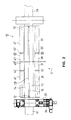
- Figure 2 schematically depicts the device illustrated in Fig. 1 when viewed in the longitudinal direction, and
- Figure 3 depicts some possible applications of the device according to the invention for use in connection with press felts of a press section.
- The advantageous embodiment example of the invention shown in Figs. 1 and 2 comprises a
suction unit part 19 which comprises asuction chamber 16 connected to the driving and tending sides by means of suction pipes 11 (tending side) and 18 (driving side). Anadjustable suction slot 15 is formed between bendable suction ribs, preferablyplastic ribs suction slot 15 in a direction S. Aspreader roll 30 which is adjustable in its curvature has been placed before thesuction ribs rollers 31 between which adjustable bearinghousings 32 have been placed, said bearing housings enabling the set of rollers formed by therollers 31, i.e. thespreader roll 30, to be made curved. Aguide roll 40 made up ofrollers 41 and bearing means 42 therebetween has been placed on the outlet side of thesuction slot 15. Anautomatic guide 20 compriseslinear guides 22 and aworm gear 23 as well as amovement base 21 and advantageously a trapezoid-thread screw 24. Doctor boxes of thedevice 10 have been denoted with thereference numeral 17 and end seals of thesuction slot 15 with thereference numeral 12. Theend seals 12 may be, for example, adjustable seals based on an overlapping joint. Thesuction ribs suction slot 15. - The device in accordance with the invention thus comprises according to the advantageous embodiment shown in Figs. 1 and 2 an
automatic guide 20, aguide roll 40, acurved spreader roll 30 and asuction unit 19 as a single device assembly. The adjustment of thesuction unit part 19 and thesuction ribs suction slot 15 is easy to accomplish, for example, by increasing the suction width at the edges with respect to the centre because thesuction ribs rollers guide roll 40 and in thespreader roll 30 have been accomplished by means of bearings lubricated with circulating grease or circulating oil or by means of permanently lubricated bearings. Therollers device 10 can be turned upside down by using a hydraulic motor or cylinder (not shown) for the purpose of cleaning. - Fig. 3 shows a schematic application of a
press section 50 in whichdevices 10 according to the invention have been placed in connection with fabrics F; 51, 52, 53, 54. Thepress section 50 illustrated in the figure comprises two press nips N1, N2 formed betweenpress rolls reference numeral 59 and rolls which comprise a suction slot have been denoted with thereference numeral 61. Aroll 60 adjustable in position is situated at the beginning of the press section in connection with asuction roll 61, a paper web being passed between said rolls from a former. - A felt and wire tracking device is advantageously used in connection with the device according to the invention, said device being based on an angle sensor and on a flap lying against the edge of the felt as well as on a measuring head, in which the flap of the measuring head lying against the edge of the felt remains in contact with the edge of the felt by means of a compression spring placed inside an oil-containing cylinder, the structure of the return mechanism of said spring resembling the structure of a conventional shock absorber. Oil or an equivalent medium flows through a piston from holes making the movement of the flap more stable, and the return force is adjustable. Two measuring heads are used for each fabric, and the signal is filtered. An angle sensor of strong construction is used as the angle sensor of the measuring head, which withstands the amounts required for longitudinal and radial load, and the measuring member constructed inside its transducer is a non-wearing capacitive transducer operating without a mechanical contact. A sensor can be used both in the measuring head and as a position sensor of the guide, in which connection the adapting of output and input impulses is easy.
- Above, the invention has been described only with reference to one of its advantageous embodiment examples, to the details of which the invention is not intended by any means to be narrowly confined.
Claims (10)
- A device (10) for use in connection with a fabric (F) in a paper machine, in particular a device (10) for use in connection with a fabric in a former or a press section of a paper machine, characterized in that the device (10) comprises subassemblies which form a single device and that the device comprises the subassemblies:- an automatic guide (20) and a guide roll for guiding the fabric (F), and a curved spreader roll (30) for spreading the fabric (F),
or- an automatic guide (20) and a guide roll for guiding the fabric (F), and a suction unit (19) for cleaning the fabric (F),
or- a curved spreader roll (30) for spreading the fabric (F), and a suction unit (19) for cleaning the fabric (F),
or- an automatic guide (20) and a guide roll for guiding the fabric (F), and a curved spreader roll (30) for spreading the fabric (F), and a suction unit (19) for cleaning the fabric (F). - A device according to claim 1, characterized in that a suction slot (15) of the suction unit (19) of the device (10) can be adjusted and that the suction slot (15) is formed between two suction ribs (13,14).
- A device according to claim 2, characterized in that the suction ribs are plastic ribs (13,14).
- A device according to claim 2 or 3, characterized in that the suction ribs (13, 14) can be adjusted in position and bent.
- A device according to any one of claims 1 to 4, characterized in that the automatic guide (20) of the device (10) comprises linear guides (22), a worm gear (23), a trapezoid-thread screw (24), and a movement base (21).
- A device according to any one of claims 1 to 5, characterized in that the spreader roll (30) of the device (10) is formed of rollers (31) having adjustable bearing housings (32) placed in the spaces therebetween in order to adjust the curvature of the spreader roll (30).
- A device according to any one of claims 1 to 6, characterized in that the guide roll (40) of the device (10) is formed of rollers (41) having bearings (42) placed therebetween.
- A device according to any one of claims 1 to 7, characterized in that suction pipes (11, 18) are arranged in connection with a suction chamber (16) of the suction unit (19) of the device (10), one of said tubes extending to the tending side and the other to the driving side.
- A device according to any one of claims 1 to 8, characterized in that end seals (12) of the suction slot (15) in the suction unit (19) of the device (10) are based on an adjustable overlapping joint.
- A device according to any one of claims 1 to 9, characterized in that the curvature of the spreader roll (30) of the device (10) is regulated by adjusting the height position of the bearing housings (32).
Applications Claiming Priority (3)
| Application Number | Priority Date | Filing Date | Title |
|---|---|---|---|
| FI990343 | 1999-02-18 | ||
| FI990343A FI107061B (en) | 1999-02-18 | 1999-02-18 | Device used in conjunction with a tissue in a paper machine |
| PCT/FI2000/000115 WO2000049224A1 (en) | 1999-02-18 | 2000-02-16 | Device for use in connection with a fabric in a paper machine |
Publications (2)
| Publication Number | Publication Date |
|---|---|
| EP1200673A1 EP1200673A1 (en) | 2002-05-02 |
| EP1200673B1 true EP1200673B1 (en) | 2007-03-28 |
Family
ID=8553840
Family Applications (1)
| Application Number | Title | Priority Date | Filing Date |
|---|---|---|---|
| EP00905095A Expired - Lifetime EP1200673B1 (en) | 1999-02-18 | 2000-02-16 | Device for use in connection with a fabric in a paper machine |
Country Status (7)
| Country | Link |
|---|---|
| US (1) | US6669817B2 (en) |
| EP (1) | EP1200673B1 (en) |
| AT (1) | ATE358210T1 (en) |
| AU (1) | AU2674500A (en) |
| DE (1) | DE60034126T2 (en) |
| FI (1) | FI107061B (en) |
| WO (1) | WO2000049224A1 (en) |
Cited By (1)
| Publication number | Priority date | Publication date | Assignee | Title |
|---|---|---|---|---|
| CN102733246A (en) * | 2012-06-19 | 2012-10-17 | 郑建新 | Automatic processing machine tool of washing paper |
Families Citing this family (5)
| Publication number | Priority date | Publication date | Assignee | Title |
|---|---|---|---|---|
| FI107061B (en) | 1999-02-18 | 2001-05-31 | Metso Paper Inc | Device used in conjunction with a tissue in a paper machine |
| FI112811B (en) * | 2002-10-29 | 2004-01-15 | Metso Paper Inc | Apparatus for controlling a tissue in a paper machine |
| FI20051086L (en) * | 2005-10-27 | 2007-04-28 | Upm Kymmene Corp | Method and apparatus for removing water from felt |
| US7721769B2 (en) * | 2007-01-19 | 2010-05-25 | Voith Patent Gmbh | Paper machine fabric with trapezoidal shaped filaments |
| DE102025000203A1 (en) * | 2025-01-20 | 2025-12-31 | Voith Patent Gmbh | Method for operating a press unit in a machine for producing a fibrous web |
Family Cites Families (18)
| Publication number | Priority date | Publication date | Assignee | Title |
|---|---|---|---|---|
| DE109444C (en) * | ||||
| US1501179A (en) * | 1920-10-12 | 1924-07-15 | Peacock James | Felt washer |
| US2043415A (en) * | 1935-10-01 | 1936-06-09 | Lawrence L Lapeyrouse | Felt cleaner for paper mills |
| US2142711A (en) * | 1936-05-01 | 1939-01-03 | Harold W Birch | Vacuum extractor |
| US2245109A (en) * | 1938-03-01 | 1941-06-10 | Lawrence L Lapeyrouse | Felt cleaner |
| US3140225A (en) * | 1962-11-29 | 1964-07-07 | Dominion Eng Works Ltd | Adjustable drainage foil for paper machines |
| US3397111A (en) * | 1965-04-26 | 1968-08-13 | Monarch Forge And Machine Work | Cleaning apparatus for paper machine press felts |
| US3841910A (en) * | 1970-04-13 | 1974-10-15 | Bird Machine Co | Liquid extracting apparatus and method |
| DE2139159C3 (en) | 1971-08-05 | 1974-08-15 | Jagenberg-Werke Ag, 4000 Duesseldorf | Device for spreading webs of material, in particular webs of paper |
| GB1435909A (en) * | 1972-12-13 | 1976-05-19 | Jwi Ltd | Spreader shower for paper making apparatus |
| DE2510492A1 (en) * | 1975-03-11 | 1976-09-23 | Dieter Rauchmaul Kunststoffver | Suction box for papermaking machine - with adjustably pivotable and mutually spaced long sieve support strips |
| DE2540923B2 (en) * | 1975-09-13 | 1978-01-12 | EMA-Dörries GmbH, Elektronik-Maschinen-Apparatebau, 5190 Stolberg | DEVICE FOR REGULATING THE TENSION OF AN ENDLESS FELT OR SCREEN IN PAPER MACHINES |
| US4474644A (en) * | 1983-05-16 | 1984-10-02 | Ole Poulsen | Felt conditioning system for papermaking machines and the like |
| FI69440C (en) * | 1983-07-22 | 1986-02-10 | Waertsilae Oy Ab | ANORDING FROM THE BANK |
| FI100412B (en) * | 1991-05-21 | 1997-11-28 | Valmet Paper Machinery Inc | A system in the press section of a paper machine for monitoring and controlling the flow of press felts |
| US5147508A (en) * | 1991-10-11 | 1992-09-15 | The Nash Engineering Company | Suction box covers for cleaning papermaking machine felts |
| FI965277L (en) * | 1996-12-31 | 1998-07-01 | Valmet Corp | Paper machine suction box and method in paper machine suction box |
| FI107061B (en) | 1999-02-18 | 2001-05-31 | Metso Paper Inc | Device used in conjunction with a tissue in a paper machine |
-
1999
- 1999-02-18 FI FI990343A patent/FI107061B/en not_active IP Right Cessation
-
2000
- 2000-02-16 AT AT00905095T patent/ATE358210T1/en not_active IP Right Cessation
- 2000-02-16 WO PCT/FI2000/000115 patent/WO2000049224A1/en not_active Ceased
- 2000-02-16 DE DE60034126T patent/DE60034126T2/en not_active Expired - Lifetime
- 2000-02-16 AU AU26745/00A patent/AU2674500A/en not_active Abandoned
- 2000-02-16 EP EP00905095A patent/EP1200673B1/en not_active Expired - Lifetime
-
2001
- 2001-08-17 US US09/932,214 patent/US6669817B2/en not_active Expired - Fee Related
Cited By (1)
| Publication number | Priority date | Publication date | Assignee | Title |
|---|---|---|---|---|
| CN102733246A (en) * | 2012-06-19 | 2012-10-17 | 郑建新 | Automatic processing machine tool of washing paper |
Also Published As
| Publication number | Publication date |
|---|---|
| US6669817B2 (en) | 2003-12-30 |
| WO2000049224A1 (en) | 2000-08-24 |
| ATE358210T1 (en) | 2007-04-15 |
| EP1200673A1 (en) | 2002-05-02 |
| FI990343L (en) | 2000-08-19 |
| FI107061B (en) | 2001-05-31 |
| DE60034126T2 (en) | 2007-12-13 |
| AU2674500A (en) | 2000-09-04 |
| US20020079077A1 (en) | 2002-06-27 |
| DE60034126D1 (en) | 2007-05-10 |
| FI990343A0 (en) | 1999-02-18 |
Similar Documents
| Publication | Publication Date | Title |
|---|---|---|
| EP0345501B1 (en) | A press with extended nip | |
| EP0345500B1 (en) | A press with extended nip | |
| US4563245A (en) | Press device, particularly for the removing of water from a web of paper | |
| JPH0465254B2 (en) | ||
| KR930007861B1 (en) | Enlarge nip press belt guide and method | |
| US5211814A (en) | Wire loading device in a paper machine | |
| US6669817B2 (en) | Device for use in connection with a fabric in a paper machine | |
| US5643416A (en) | Extended nip press with oscillating blanket for extended wear | |
| EP0730060B1 (en) | Loading element for a draining device in a paper machine | |
| US4110156A (en) | Compact press at the web transfer position of a paper making machine | |
| US6203615B1 (en) | Doctoring device | |
| CA2506070C (en) | Sealing arrangement against a moving fabric | |
| US4547266A (en) | Apparatus for providing selectively differentiated vacuum across a papermaking machine width | |
| KR100416007B1 (en) | Drainage process and apparatus of papermaking network or press section such as paper machine | |
| EP1285121B1 (en) | Shoe press | |
| US5744006A (en) | Apparatus for dewatering mixtures of fibrous and liquid materials | |
| CN1871401B (en) | Pressing device | |
| KR100356281B1 (en) | Gap former in a paper machine | |
| US20050098290A1 (en) | System and method for influencing and/or monitoring a press pressure profile | |
| WO2008046960A1 (en) | Pressing arrangement in the processing apparatus of a paper/board machine or finishing machine with a metal belt loop | |
| FI65832C (en) | PRESSAANORDNING FOER FIBERBANA MED BRED PRESSZON | |
| KR100469795B1 (en) | Wide nip press with fluctuating blanket of extended wear area and how to extend the life of the fluctuating blanket | |
| US6517683B2 (en) | Shoe press with movable guides to alter machine direction shoe position | |
| KR100266757B1 (en) | Top roll lifting arrangement for a press in a papermaking or boardmaking machine |
Legal Events
| Date | Code | Title | Description |
|---|---|---|---|
| PUAI | Public reference made under article 153(3) epc to a published international application that has entered the european phase |
Free format text: ORIGINAL CODE: 0009012 |
|
| AK | Designated contracting states |
Kind code of ref document: A1 Designated state(s): AT BE CH CY DE DK ES FI FR GB GR IE IT LI LU |
|
| 17P | Request for examination filed |
Effective date: 20010712 |
|
| GRAP | Despatch of communication of intention to grant a patent |
Free format text: ORIGINAL CODE: EPIDOSNIGR1 |
|
| RBV | Designated contracting states (corrected) |
Designated state(s): AT BE CH CY DE DK ES FI FR GB GR IE IT LI LU MC NL PT SE |
|
| GRAS | Grant fee paid |
Free format text: ORIGINAL CODE: EPIDOSNIGR3 |
|
| GRAA | (expected) grant |
Free format text: ORIGINAL CODE: 0009210 |
|
| AK | Designated contracting states |
Kind code of ref document: B1 Designated state(s): AT BE CH CY DE DK ES FI FR GB GR IE IT LI LU MC NL PT SE |
|
| PG25 | Lapsed in a contracting state [announced via postgrant information from national office to epo] |
Ref country code: AT Free format text: LAPSE BECAUSE OF FAILURE TO SUBMIT A TRANSLATION OF THE DESCRIPTION OR TO PAY THE FEE WITHIN THE PRESCRIBED TIME-LIMIT Effective date: 20070328 Ref country code: CH Free format text: LAPSE BECAUSE OF FAILURE TO SUBMIT A TRANSLATION OF THE DESCRIPTION OR TO PAY THE FEE WITHIN THE PRESCRIBED TIME-LIMIT Effective date: 20070328 Ref country code: BE Free format text: LAPSE BECAUSE OF FAILURE TO SUBMIT A TRANSLATION OF THE DESCRIPTION OR TO PAY THE FEE WITHIN THE PRESCRIBED TIME-LIMIT Effective date: 20070328 Ref country code: NL Free format text: LAPSE BECAUSE OF FAILURE TO SUBMIT A TRANSLATION OF THE DESCRIPTION OR TO PAY THE FEE WITHIN THE PRESCRIBED TIME-LIMIT Effective date: 20070328 Ref country code: LI Free format text: LAPSE BECAUSE OF FAILURE TO SUBMIT A TRANSLATION OF THE DESCRIPTION OR TO PAY THE FEE WITHIN THE PRESCRIBED TIME-LIMIT Effective date: 20070328 Ref country code: FI Free format text: LAPSE BECAUSE OF FAILURE TO SUBMIT A TRANSLATION OF THE DESCRIPTION OR TO PAY THE FEE WITHIN THE PRESCRIBED TIME-LIMIT Effective date: 20070328 |
|
| REG | Reference to a national code |
Ref country code: GB Ref legal event code: FG4D |
|
| REG | Reference to a national code |
Ref country code: CH Ref legal event code: EP |
|
| REF | Corresponds to: |
Ref document number: 60034126 Country of ref document: DE Date of ref document: 20070510 Kind code of ref document: P |
|
| REG | Reference to a national code |
Ref country code: IE Ref legal event code: FG4D |
|
| PG25 | Lapsed in a contracting state [announced via postgrant information from national office to epo] |
Ref country code: SE Free format text: LAPSE BECAUSE OF FAILURE TO SUBMIT A TRANSLATION OF THE DESCRIPTION OR TO PAY THE FEE WITHIN THE PRESCRIBED TIME-LIMIT Effective date: 20070628 |
|
| PG25 | Lapsed in a contracting state [announced via postgrant information from national office to epo] |
Ref country code: ES Free format text: LAPSE BECAUSE OF FAILURE TO SUBMIT A TRANSLATION OF THE DESCRIPTION OR TO PAY THE FEE WITHIN THE PRESCRIBED TIME-LIMIT Effective date: 20070709 |
|
| REG | Reference to a national code |
Ref country code: CH Ref legal event code: PL |
|
| NLV1 | Nl: lapsed or annulled due to failure to fulfill the requirements of art. 29p and 29m of the patents act | ||
| EN | Fr: translation not filed | ||
| PG25 | Lapsed in a contracting state [announced via postgrant information from national office to epo] |
Ref country code: DK Free format text: LAPSE BECAUSE OF FAILURE TO SUBMIT A TRANSLATION OF THE DESCRIPTION OR TO PAY THE FEE WITHIN THE PRESCRIBED TIME-LIMIT Effective date: 20070328 |
|
| PLBE | No opposition filed within time limit |
Free format text: ORIGINAL CODE: 0009261 |
|
| STAA | Information on the status of an ep patent application or granted ep patent |
Free format text: STATUS: NO OPPOSITION FILED WITHIN TIME LIMIT |
|
| 26N | No opposition filed |
Effective date: 20080102 |
|
| PG25 | Lapsed in a contracting state [announced via postgrant information from national office to epo] |
Ref country code: IT Free format text: LAPSE BECAUSE OF FAILURE TO SUBMIT A TRANSLATION OF THE DESCRIPTION OR TO PAY THE FEE WITHIN THE PRESCRIBED TIME-LIMIT Effective date: 20070328 Ref country code: FR Free format text: LAPSE BECAUSE OF FAILURE TO SUBMIT A TRANSLATION OF THE DESCRIPTION OR TO PAY THE FEE WITHIN THE PRESCRIBED TIME-LIMIT Effective date: 20071116 Ref country code: GR Free format text: LAPSE BECAUSE OF FAILURE TO SUBMIT A TRANSLATION OF THE DESCRIPTION OR TO PAY THE FEE WITHIN THE PRESCRIBED TIME-LIMIT Effective date: 20070629 |
|
| GBPC | Gb: european patent ceased through non-payment of renewal fee |
Effective date: 20080216 |
|
| PG25 | Lapsed in a contracting state [announced via postgrant information from national office to epo] |
Ref country code: MC Free format text: LAPSE BECAUSE OF NON-PAYMENT OF DUE FEES Effective date: 20080228 |
|
| PG25 | Lapsed in a contracting state [announced via postgrant information from national office to epo] |
Ref country code: FR Free format text: LAPSE BECAUSE OF FAILURE TO SUBMIT A TRANSLATION OF THE DESCRIPTION OR TO PAY THE FEE WITHIN THE PRESCRIBED TIME-LIMIT Effective date: 20070328 |
|
| PG25 | Lapsed in a contracting state [announced via postgrant information from national office to epo] |
Ref country code: IE Free format text: LAPSE BECAUSE OF NON-PAYMENT OF DUE FEES Effective date: 20080218 |
|
| PG25 | Lapsed in a contracting state [announced via postgrant information from national office to epo] |
Ref country code: GB Free format text: LAPSE BECAUSE OF NON-PAYMENT OF DUE FEES Effective date: 20080216 |
|
| PG25 | Lapsed in a contracting state [announced via postgrant information from national office to epo] |
Ref country code: CY Free format text: LAPSE BECAUSE OF FAILURE TO SUBMIT A TRANSLATION OF THE DESCRIPTION OR TO PAY THE FEE WITHIN THE PRESCRIBED TIME-LIMIT Effective date: 20070328 |
|
| PGFP | Annual fee paid to national office [announced via postgrant information from national office to epo] |
Ref country code: DE Payment date: 20100219 Year of fee payment: 11 |
|
| PG25 | Lapsed in a contracting state [announced via postgrant information from national office to epo] |
Ref country code: LU Free format text: LAPSE BECAUSE OF NON-PAYMENT OF DUE FEES Effective date: 20080216 |
|
| PG25 | Lapsed in a contracting state [announced via postgrant information from national office to epo] |
Ref country code: PT Free format text: LAPSE BECAUSE OF FAILURE TO SUBMIT A TRANSLATION OF THE DESCRIPTION OR TO PAY THE FEE WITHIN THE PRESCRIBED TIME-LIMIT Effective date: 20070328 |
|
| REG | Reference to a national code |
Ref country code: DE Ref legal event code: R119 Ref document number: 60034126 Country of ref document: DE Effective date: 20110901 |
|
| PG25 | Lapsed in a contracting state [announced via postgrant information from national office to epo] |
Ref country code: DE Free format text: LAPSE BECAUSE OF NON-PAYMENT OF DUE FEES Effective date: 20110901 |