EP1199858A2 - Scrambler for Q-mode and data-mode transmission - Google Patents
Scrambler for Q-mode and data-mode transmission Download PDFInfo
- Publication number
- EP1199858A2 EP1199858A2 EP01308609A EP01308609A EP1199858A2 EP 1199858 A2 EP1199858 A2 EP 1199858A2 EP 01308609 A EP01308609 A EP 01308609A EP 01308609 A EP01308609 A EP 01308609A EP 1199858 A2 EP1199858 A2 EP 1199858A2
- Authority
- EP
- European Patent Office
- Prior art keywords
- mode
- data
- scrambler
- data communication
- communication system
- Prior art date
- Legal status (The legal status is an assumption and is not a legal conclusion. Google has not performed a legal analysis and makes no representation as to the accuracy of the status listed.)
- Withdrawn
Links
Images


Classifications
-
- H—ELECTRICITY
- H04—ELECTRIC COMMUNICATION TECHNIQUE
- H04L—TRANSMISSION OF DIGITAL INFORMATION, e.g. TELEGRAPHIC COMMUNICATION
- H04L25/00—Baseband systems
- H04L25/02—Details ; arrangements for supplying electrical power along data transmission lines
- H04L25/03—Shaping networks in transmitter or receiver, e.g. adaptive shaping networks
- H04L25/03828—Arrangements for spectral shaping; Arrangements for providing signals with specified spectral properties
Definitions
- ITU contributions have proposed a low power mode (i.e., "Q-mode,") in the transmitter.
- Q-mode a low power mode
- the modem is still in the ready state, but enters a low power mode during periods of no data transmission.
- HC-029R1 One ITU contribution, HC-029R1, formally defines a semi-stationary Q-mode signal, that employs a pair of pseudo-random bit sequence ("PRBS") generators, each with a period of greater than 4000.
- PRBS pseudo-random bit sequence
- requiring two PRBS generators as such correspondingly requires additional hardware in the modem, as well as additional overhead associated with the overall system.
- the two PRBS generators sit idle.
- the data communication node may be, for example, a modem (such as an ADSL modem).
- the data communication node in turn has a transmitter, which itself has a scrambler.
- the transmitter uses the scrambler to operate in two modes.
- the first mode is a data communication mode, which, in the case when the data communication node is an ADSL modem, is SHOWTIME.
- the scrambler is used to scramble data that is communicated by the transmitter.
- the second mode is a non-data mode, which in the case when the data communication node is an ADSL transmitter, may be Q-mode.
- the scrambler is used to generate a non-data mode signal.
- non-data mode operation a non-data mode input to the scrambler is selected.
- a non-data mode signal is then generated, using a first output of the scrambler.
- the non-data mode signal is output, using a second output of the scrambler, for communication by the transmitter. This process is repeated for successive outputs of the scrambler, for as long as the non-data mode input to the scrambler is selected.
- Fig.1 is a block diagram of a generic communication system that may be employed in connection with the present invention.
- Fig. 2 is a functional block diagram of an ADSL modem transmitter according to the present invention.
- Fig. 3 is a schematic block diagram illustrating one embodiment by which the scrambler of Fig. 2 performs the two functions shown in Fig. 2.
- Fig. 4 is a block diagram of one embodiment of Q-mode signal generation circuitry in accordance with the present invention.
- Fig. 5 illustrates a more detailed embodiment of the Q-mode signal generation circuitry of Fig. 4.
- Fig. 6 is a flow diagram of overall control for mode selection in accordance with the present invention.
- Fig. 7 is a depiction of a generic scrambler that may be employed in connection with the present invention.
- Fig. 8 is one specific embodiment of a scrambler that may be employed in connection with the present invention.
- Fig. 9 is a scrambler based on the scrambler of Fig. 8 but with alternate outputs selected in such a way that two separate output streams are produced.
- Fig. 10 is a depiction of a generic PRBS generator in accordance with the present invention.
- Fig. 11 is one specific embodiment of the PRBS generator of Fig. 10 in accordance with the present invention.
- Fig. 12 is a PRBS generator based on the PRBS generator of Figure 11, but with alternate outputs selected in such a way that two separate output streams are produced, in accordance with the present invention.
- Fig.1 is a block diagram of a generic communication system that may be employed in connection with the present invention.
- the system comprises a first communication node 101, a second communication node 111, and a channel 109 that communicatively couples the nodes 101 and 111.
- the communication nodes may be, for example, ADSL modems or any other type of transceiver device that transmits or receives data over a channel.
- the first communication node 101 comprises a transmitter 105, a receiver 103 and a processor 106.
- the processor 106 may comprise, for example, a microprocessor.
- the first communication node 101 is communicatively coupled to a user 100 (e.g., a computer) via communication link 110, and to the channel 109 via communication links 107 and 108.
- the second communication node 111 comprises a transmitter 115, a receiver 114 and a processor 118.
- the processor 118 like processor 106, may comprise, for example, a microprocessor.
- the second communication node 111 is likewise communicatively coupled to a user 120 (again a computer, for example) via communication link 121, and to the channel 109 via communication links 112 and 113.
- the user 100 can communicate information to the user 120 using the first communication node 101, the channel 109 and the second communication node 111.
- the user 100 communicates the information to the first communication node 101 via communication link 110.
- the information is transformed in the transmitter 105 to match the restrictions imposed by the channel 109.
- the transmitter 105 then communicates the information to the channel 109 via communication link 107.
- the receiver 114 of the second communication node 111 next receives, via communication link 113, the information from the channel 109 and transforms it into a form usable by the user 120.
- the information is communicated from the second communication node 111 to the user 120 via the communication link 121.
- Communication of information from the user 120 to the user 100 may also be achieved in a similar manner. In either case, the information transmitted/received may also be processed using the processors 106/118.
- FIG. 2 is a functional block diagram of an ADSL modem transmitter according to the present invention.
- a transmitter 201 comprises a scrambler 203 and control 205.
- Control 205 causes the transmitter 201 to operate in two different modes, namely a data transmission or "SHOWTIME" mode (designated functionally by block 207) and a non-data mode or "Q-mode” (designated functionally by block 209).
- the non-data mode may be, for example, a quiescent, low power mode.
- a switch 211 is shown in Fig. 2 as selecting between the data and non-data modes, the switch 211 is not necessarily a hardware switch per se, but rather an abstract selection mechanism, as explained more completely below.
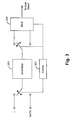
- Fig. 3 is a schematic block diagram illustrating one embodiment by which the scrambler of Fig. 2 performs the two functions shown in Fig. 2. Similar to control 205 of Fig. 2, control 301 acts as a selector between Q-mode operation and data operation. In Q-mode, control 301 selects "1" as the input to scrambler 303, employs the scrambler 303 output for Q-mode purposes, and selects the Q-mode signal as the output of multiplexor 305.
- control 301 selects the input of scrambler 303 to be unscrambled data, employs the output of the scrambler 303 to be scrambled data, and selects the data mode signal as the output of mutiplexor 305. In either mode, the output of multiplexor 305 is sent to a line driver (not shown).
- a single scrambler is used to scramble the data during data transmission and to control the generation of the Q-mode signal.
- Fig. 4 is a block diagram of one embodiment of Q-mode signal generation circuitry in accordance with the present invention.
- Q-mode i.e., "1" at the input of scrambler 401
- the scrambler 401 switches between generating the Q-mode signal and outputting the Q-mode signal. More specifically, for each symbol of the Q-mode signal, two successive outputs from the scrambler 401 are used. The first out put selects whether the basic symbols (i.e., S1 and S2) or their inverses should be generated. In the embodiment of Fig. 4, if the first output is "0,” then S1 and S2 are presented at the input of multiplexor 403. If instead the first output is "1,” then the inverse of S1 and S2 are presented at the inputs of multiplexor 403.
- the second output of scambler 401 is then presented to control 405, which selects the output of the multiplexor 401.
- the output of multiplexor 410 represents the Q-mode signal.
- Fig. 5 illustrates a more detailed embodiment of the Q-mode signal generation circuitry of Fig. 4.
- a scrambler 501 with its input clamped to one generates an output sequence of bits at a rate equal to twice the symbol rate of the system.
- the outputs of the scrambler 501 are alternately connected to a first input 505 and a second input 507 by means of a switch 503.
- the first input 505 is used by multiplier 513 to either invert or not invert (i.e. multiply by +1 or -1) a stationary signal 509, resulting in a first signal 514.
- the same first input 505 also is used by multiplier 515 to either invert or not invert a non-stationary signal 511, resulting in a second signal 516.
- the first signal 514 and the second signal 516 form the inputs to a multiplexor 517.
- the second input 507 is applied to the input of a serial-to-parallel convertor 531 that converts groups of bits from the second input 507 to a first 8-bit integer 535.
- a duty cycle 533 i.e. a positive number between 0 and 1 is scaled in scaler 534 to an 8-bit positive integer (i.e., an integer between 0 and 255 inclusive) to produce a second 8-bit integer 537.
- a comparator 539 produces an output 518 that is 1 whenever the first 8-bit integer 535 is less than the second 8-bit integer 537; the output 518 is 0 otherwise.
- the output 518 is the select input 519 of multiplexor 517.
- the output of multiplexor 517 is Q-mode signal 521, which is comprised of first signal 514 whenever the select input 519 is "1," and second signal 516 whenever the select input 519 is "0.”
- a final multiplexor 525 operating under control of Q-mode enable 527, has an output signal 529 that is Q-mode signal 521 whenever Q-mode enable 527 is 1; the output signal 529 is the data mode signal 523 whenever Q-mode enable 527 is "0.” Subsequent processing stages in the ADSL transmitter convert the output signal 529 into a signal that is transmitted by the ADSL transmitter.
- Fig. 6 is a flow diagram of overall control for mode selection in accordance with the present invention.
- inputs to the system are examined (block 601).
- "Inputs" may be, for example, user data, internally generated overhead data (e.g., system status or commands), etc., or no data at all. If it is determined that data is present at the inputs (block 603), then a determination is made whether the system is in the data mode (block 605). If the system is indeed in the data mode, the system simply operates in the data mode (block 607). If it is not in the data mode (as determined at block 605), the system first configures the scrambler for data mode operation (block 609), and then operates in the data mode (block 607).
- Fig. 7 is a depiction of a generic scrambler that may be employed in connection with the present invention.
- Scrambler 701 outputs a pseudo random bit sequence with a period of 2 N -1, where each of j 1,j2,... j N comprises one of "0" or "1" and ⁇ j 1, j 2,... j N ⁇ (not all equal to "1") represents the initial state of the scrambler 701.
- ⁇ c 1, c 2 ... c N ⁇ represents the coefficients of a primitive polynomial.
- Fig. 8 is one specific embodiment of the scrambler of Fig. 7 that may be employed in connection with the present invention.
- Scrambler 801 is defined for ADSL data transmission in G.992.1 and G.992.2.
- the scrambler 801 of Fig. 8 is based on the primitive polynomial 1 ⁇ x -18 ⁇ x -23 with the ⁇ symbol used to denote addition mod 2.
- the scrambler 801 input is clamped to "1," the scrambler 801 output becomes a pseudo-random bit sequence with a period of 2 23 -1.
- Equation (2) expresses the fundamental recurrence relation for the scrambler of Fig. 8. Further properties of this scrambler make it attractive for generating pseudo-random sequences. Of course, a whole family of scramblers can be defined in a similar way.
- FIG. 10 is a depiction of a generic PRBS generator that may be employed in connection with the present invention.
- PRBS generator 1001 outputs a pseudo random bit sequence with a period of 2 N -1, where each of i 1 , i 2 , ... i N comprises one of "0" or "1" and ⁇ i 1 , i 2 , ... i N ⁇ (not all equal to "0") represents the initial state of the PRBS generator 1001.
- ⁇ c 1 , c 2 ... c N ⁇ represents the coefficients of a primitive polynomial.
- Fig. 11 is one specific embodiment of the PRBS generator of Fig. 10 in accordance with the present invention.
- the PRBS generator 1101 of Fig. 11 is based on the same polynomial as that upon which Fig. 8 is based.
- the sequence ⁇ a j , a j +1 , a j +2 ,... ⁇ represent the output sequence emitted by the PRBS where j is an arbitrary integer representing time.
- the initial state of the generator is ⁇ a j +1 , a j +2 ,..., a j +23 ⁇ for some j .
- Equation (2) expresses the fundamental recurrence relation for the PRBS generator. Further properties of this PRBS generator make it attractive for generating pseudo-random sequences. Of course, a whole family of PRBS generators can be defined in a similar way.
- PRBS generator 1201 of Fig. 12 which is based on the PRBS generator of Fig. 11, but with alternate outputs selected in such a way that two separate output streams are produced (in accordance with the present invention).
Abstract
Description
Equation (2) expresses the fundamental recurrence relation for the scrambler of Fig. 8. Further properties of this scrambler make it attractive for generating pseudo-random sequences. Of course, a whole family of scramblers can be defined in a similar way.


Claims (22)
- A communication system comprising:a data communication node; anda transmitter located in the data communication node, the transmitter having a scrambler, the transmitter using the scrambler to operate in a first, data communication mode and in a second, non-data mode.
- The data communication system of claim 1 wherein the data communication node comprises an ADSL modem.
- The data communication system of claim 2 wherein the first, data communication mode comprises SHOWTIME.
- The data communication system of claim 3 wherein the scrambler scrambles data during SHOWTIME
- The data communication system of claim 2 wherein the second, non-data mode comprises a Q-mode.
- The data communication system of claim 5 wherein the scrambler at least partially generates a Q-mode signal.
- The data communication system of claim 1 wherein the scrambler scrambles data during the first, data communication mode.
- The data communication system of claim 1 wherein the scrambler at least partially generates a non-data mode signal.
- A method of operating a transmitter in a data communication system, the transmitter having a scrambler, the method comprising:determining that data is present at at least one input;determining whether the scrambler is configured for a data communication mode;configuring the scrambler for the data communication mode if a determination is made that the scrambler is not configured for the data communication mode;operating in the data communication mode;determining that data is not present at the at least one input;determining whether the scrambler is configured for a non-data mode;configuring the scrambler for the non-data mode if a determination is made that the scrambler is not configured for the non-data mode; andoperating in the non-data mode.
- The method of claim 9 wherein operating in the data communication mode comprises scrambling, by the scrambler, data received at the at least one input.
- The method of claim 9 wherein operating in the non-data communication mode comprises generating, at least partially by the scrambler, a non-data mode signal.
- The method of claim 9 wherein the transmitter is located in an ADSL modem.
- The data communication system of claim 12 wherein the data communication mode comprises SHOWTIME.
- The data communication system of claim 13 wherein operating in the data communication mode comprises scrambling, by the scrambler, data during SHOWTIME
- The data communication system of claim 12 wherein the non-data mode comprises a Q-mode.
- The data communication system of claim 15 wherein operating in the non-data mode comprises generating, at least partially by the scrambler, a Q-mode signal.
- A method of operating a transmitter in a data communication system, the transmitter having a scrambler, the method comprising:selecting a non-data mode input to the scrambler;generating, using a first output of the scrambler, a non-data mode signal; andcontrolling, using a second output of the scrambler, the output of the non-data mode signal.
- The method of claim 17 further comprising repeating the generating and controlling for as long as the non-data mode input to the scrambler is selected.
- The method of claim 17 further comprising:selecting a data communication mode input to the scrambler; andscrambling data received for communication.
- The method of claim 19 wherein the transmitter is located in an ADSL modem.
- The data communication system of claim 20 wherein the data communication mode comprises SHOWTIME.
- The data communication system of claim 20 wherein the non-data mode comprises a Q-mode.
Applications Claiming Priority (4)
| Application Number | Priority Date | Filing Date | Title |
|---|---|---|---|
| US24112600P | 2000-10-16 | 2000-10-16 | |
| US241126P | 2000-10-16 | ||
| US906410 | 2001-07-16 | ||
| US09/906,410 US7054379B2 (en) | 2000-10-16 | 2001-07-16 | Data scrambler generation of pseudo-random bit sequence for semi-stationary Q-mode signal |
Publications (2)
| Publication Number | Publication Date |
|---|---|
| EP1199858A2 true EP1199858A2 (en) | 2002-04-24 |
| EP1199858A3 EP1199858A3 (en) | 2006-01-11 |
Family
ID=26934024
Family Applications (1)
| Application Number | Title | Priority Date | Filing Date |
|---|---|---|---|
| EP01308609A Withdrawn EP1199858A3 (en) | 2000-10-16 | 2001-10-09 | Scrambler for Q-mode and data-mode transmission |
Country Status (2)
| Country | Link |
|---|---|
| US (2) | US7054379B2 (en) |
| EP (1) | EP1199858A3 (en) |
Cited By (3)
| Publication number | Priority date | Publication date | Assignee | Title |
|---|---|---|---|---|
| WO2002078244A1 (en) * | 2001-03-27 | 2002-10-03 | Aware, Inc. | Receiver transparent q-mode |
| WO2004082230A1 (en) * | 2003-03-14 | 2004-09-23 | Upzide Labs Ab | Arrangements and methods for a digital communication system |
| US7558329B2 (en) | 2001-03-27 | 2009-07-07 | Aware, Inc. | Systems and methods for implementing receiver transparent Q-mode |
Families Citing this family (3)
| Publication number | Priority date | Publication date | Assignee | Title |
|---|---|---|---|---|
| US20030031240A1 (en) * | 2001-07-31 | 2003-02-13 | Redfern Arthur J. | Downstream only suspend-type Q-Mode |
| US8848914B2 (en) * | 2008-11-18 | 2014-09-30 | Qualcomm Incorporated | Spectrum authorization and related communications methods and apparatus |
| US20110191129A1 (en) * | 2010-02-04 | 2011-08-04 | Netzer Moriya | Random Number Generator Generating Random Numbers According to an Arbitrary Probability Density Function |
Family Cites Families (6)
| Publication number | Priority date | Publication date | Assignee | Title |
|---|---|---|---|---|
| JP3051223B2 (en) | 1991-10-02 | 2000-06-12 | 富士通株式会社 | Cell transmission circuit |
| US6201830B1 (en) * | 1997-06-11 | 2001-03-13 | Texas Instruments Incorporated | Low computation idle transmission method for DSL modems |
| US6052411A (en) * | 1998-04-06 | 2000-04-18 | 3Com Corporation | Idle mode for digital subscriber line |
| US6519280B1 (en) * | 1999-03-02 | 2003-02-11 | Legerity, Inc. | Method and apparatus for inserting idle symbols |
| US6885699B2 (en) * | 2000-07-24 | 2005-04-26 | Stmicroelectronics Ltd. | Semi-stationary quiescent mode transmission |
| KR20040004562A (en) * | 2001-03-27 | 2004-01-13 | 어웨어, 인크. | Receiver Transparent Q-Mode |
-
2001
- 2001-07-16 US US09/906,410 patent/US7054379B2/en not_active Expired - Fee Related
- 2001-10-09 EP EP01308609A patent/EP1199858A3/en not_active Withdrawn
-
2006
- 2006-05-03 US US11/416,541 patent/US7593476B2/en not_active Expired - Fee Related
Non-Patent Citations (1)
| Title |
|---|
| "Asymmetric Digital Subscriber Line (ADSL) transceivers", ITU-T SERIES G: TRANSMISSION SYSTEMS AND MEDIA, DIGITAL SYSTEMS AND NETWORKS, vol. ITU-T G992.1, June 1999 (1999-06-01), pages 37 - 37 * |
Cited By (9)
| Publication number | Priority date | Publication date | Assignee | Title |
|---|---|---|---|---|
| WO2002078244A1 (en) * | 2001-03-27 | 2002-10-03 | Aware, Inc. | Receiver transparent q-mode |
| US6731695B2 (en) | 2001-03-27 | 2004-05-04 | Aware, Inc. | Systems and methods for implementing receiver transparent Q-mode |
| US7558329B2 (en) | 2001-03-27 | 2009-07-07 | Aware, Inc. | Systems and methods for implementing receiver transparent Q-mode |
| US8335271B2 (en) | 2001-03-27 | 2012-12-18 | Tq Delta, Llc | Systems and methods for implementing receiver transparent Q-mode |
| US8792574B2 (en) | 2001-03-27 | 2014-07-29 | TQ Detla, LLC | Systems and methods for implementing receiver transparent Q-mode |
| US9191039B2 (en) | 2001-03-27 | 2015-11-17 | Tq Delta, Llc | Randomization using an XOR scrambler in multicarrier communications |
| US10419059B2 (en) | 2001-03-27 | 2019-09-17 | Tq Delta, Llc | Systems and methods for implementing receiver transparent Q-mode |
| WO2004082230A1 (en) * | 2003-03-14 | 2004-09-23 | Upzide Labs Ab | Arrangements and methods for a digital communication system |
| US7672392B2 (en) | 2003-03-14 | 2010-03-02 | Ericsson Ab | Arrangements and methods for a digital communication system |
Also Published As
| Publication number | Publication date |
|---|---|
| US20020057802A1 (en) | 2002-05-16 |
| EP1199858A3 (en) | 2006-01-11 |
| US7593476B2 (en) | 2009-09-22 |
| US20070121755A1 (en) | 2007-05-31 |
| US7054379B2 (en) | 2006-05-30 |
Similar Documents
| Publication | Publication Date | Title |
|---|---|---|
| US7593476B2 (en) | Data scrambler generation of pseudo-random bit sequence for semi-stationary Q-mode signal | |
| US7986783B2 (en) | Data transmitting apparatus | |
| EP0635956B1 (en) | Encryption apparatus, communication system using the same and method therefor | |
| JP2005518720A (en) | M-ary orthogonal coded communication method and system | |
| EP1655917B1 (en) | Two-stage block-synchronization and scrambling | |
| TW200501623A (en) | Frequency hop sequences for multi-band communication systems | |
| JP2006520578A (en) | Method and apparatus for reducing discrete power spectral density components of signals transmitted in a broadband communication system | |
| EP0909055A3 (en) | Pseudo-random number generating method and apparatus therefor | |
| KR20070045208A (en) | System and method for the mitigation of spectral lines in an ultrawide bandwitdh transceiver | |
| JP5130377B2 (en) | Method for selecting frequency baseband of spreading code, adaptive frequency selective spreader using the same, and transmission / reception apparatus using the same | |
| EP1278347B1 (en) | System and method for the rapid generation of Q-mode signals with a low peak-to-average power ratio | |
| JP2004153694A (en) | Scrambler, transmitter and receiver | |
| EP1111785A9 (en) | Method and device for self-clock controlled pseudo random noise (PN) sequence generation | |
| JP3358953B2 (en) | Pseudo-random bit string generator and cryptographic communication method using the same | |
| JP2007518368A (en) | Ultra wide band scrambler to reduce power spectral density | |
| US20080252496A1 (en) | High-Rate Random Bitstream Generation | |
| JPH1093548A (en) | Pseudo random bit stream generator and ciphering communication method using the same | |
| WO2007001254A1 (en) | Spread spectrum clock and method for message timing in a communication system | |
| Sharma et al. | DSP based implementation of scrambler for 56Kbps modem | |
| KR100416971B1 (en) | Random keystream generation apparatus and method for use in a cryptosystem | |
| RU2291578C1 (en) | Method for stream encryption of data | |
| Akutsu et al. | 192 km relay transmission and HDTV transmission experiments by Quantum Yuen‐2000 transceiver | |
| RU2228575C2 (en) | Method for digital data transfer in pseudorandom operating frequency tuned link | |
| Lee et al. | Reliable and Secure Voice Encryption over GSM Voice Channel | |
| RU2215370C1 (en) | Method for transmitting digital information over radio link with pseudorandom operating frequency tuning |
Legal Events
| Date | Code | Title | Description |
|---|---|---|---|
| PUAI | Public reference made under article 153(3) epc to a published international application that has entered the european phase |
Free format text: ORIGINAL CODE: 0009012 |
|
| AK | Designated contracting states |
Kind code of ref document: A2 Designated state(s): AT BE CH CY DE DK ES FI FR GB GR IE IT LI LU MC NL PT SE TR |
|
| AX | Request for extension of the european patent |
Free format text: AL;LT;LV;MK;RO;SI |
|
| PUAL | Search report despatched |
Free format text: ORIGINAL CODE: 0009013 |
|
| AK | Designated contracting states |
Kind code of ref document: A3 Designated state(s): AT BE CH CY DE DK ES FI FR GB GR IE IT LI LU MC NL PT SE TR |
|
| AX | Request for extension of the european patent |
Extension state: AL LT LV MK RO SI |
|
| 17P | Request for examination filed |
Effective date: 20060711 |
|
| AKX | Designation fees paid |
Designated state(s): DE FR GB |
|
| RAP1 | Party data changed (applicant data changed or rights of an application transferred) |
Owner name: BROADCOM CORPORATION |
|
| 17Q | First examination report despatched |
Effective date: 20071010 |
|
| GRAP | Despatch of communication of intention to grant a patent |
Free format text: ORIGINAL CODE: EPIDOSNIGR1 |
|
| INTG | Intention to grant announced |
Effective date: 20160718 |
|
| STAA | Information on the status of an ep patent application or granted ep patent |
Free format text: STATUS: THE APPLICATION IS DEEMED TO BE WITHDRAWN |
|
| 18D | Application deemed to be withdrawn |
Effective date: 20161129 |