EP1199850A1 - A data packet switching node accommodating very high bit rate interfaces - Google Patents
A data packet switching node accommodating very high bit rate interfaces Download PDFInfo
- Publication number
- EP1199850A1 EP1199850A1 EP00440281A EP00440281A EP1199850A1 EP 1199850 A1 EP1199850 A1 EP 1199850A1 EP 00440281 A EP00440281 A EP 00440281A EP 00440281 A EP00440281 A EP 00440281A EP 1199850 A1 EP1199850 A1 EP 1199850A1
- Authority
- EP
- European Patent Office
- Prior art keywords
- input
- output
- segments
- data packet
- ports
- Prior art date
- Legal status (The legal status is an assumption and is not a legal conclusion. Google has not performed a legal analysis and makes no representation as to the accuracy of the status listed.)
- Granted
Links
- 239000011159 matrix material Substances 0.000 claims abstract description 13
- 230000006870 function Effects 0.000 claims description 4
- 239000004744 fabric Substances 0.000 description 3
- 239000013256 coordination polymer Substances 0.000 description 2
- 238000010586 diagram Methods 0.000 description 2
- 238000013507 mapping Methods 0.000 description 2
- 238000000034 method Methods 0.000 description 2
- 230000005540 biological transmission Effects 0.000 description 1
- 230000003111 delayed effect Effects 0.000 description 1
- 230000001419 dependent effect Effects 0.000 description 1
- 230000008520 organization Effects 0.000 description 1
- 230000001360 synchronised effect Effects 0.000 description 1
Images


Classifications
-
- H—ELECTRICITY
- H04—ELECTRIC COMMUNICATION TECHNIQUE
- H04L—TRANSMISSION OF DIGITAL INFORMATION, e.g. TELEGRAPHIC COMMUNICATION
- H04L49/00—Packet switching elements
- H04L49/60—Software-defined switches
- H04L49/608—ATM switches adapted to switch variable length packets, e.g. IP packets
-
- H—ELECTRICITY
- H04—ELECTRIC COMMUNICATION TECHNIQUE
- H04L—TRANSMISSION OF DIGITAL INFORMATION, e.g. TELEGRAPHIC COMMUNICATION
- H04L49/00—Packet switching elements
- H04L49/30—Peripheral units, e.g. input or output ports
-
- H—ELECTRICITY
- H04—ELECTRIC COMMUNICATION TECHNIQUE
- H04L—TRANSMISSION OF DIGITAL INFORMATION, e.g. TELEGRAPHIC COMMUNICATION
- H04L49/00—Packet switching elements
- H04L49/30—Peripheral units, e.g. input or output ports
- H04L49/3072—Packet splitting
-
- H—ELECTRICITY
- H04—ELECTRIC COMMUNICATION TECHNIQUE
- H04L—TRANSMISSION OF DIGITAL INFORMATION, e.g. TELEGRAPHIC COMMUNICATION
- H04L49/00—Packet switching elements
- H04L49/30—Peripheral units, e.g. input or output ports
- H04L49/3081—ATM peripheral units, e.g. policing, insertion or extraction
-
- H—ELECTRICITY
- H04—ELECTRIC COMMUNICATION TECHNIQUE
- H04L—TRANSMISSION OF DIGITAL INFORMATION, e.g. TELEGRAPHIC COMMUNICATION
- H04L12/00—Data switching networks
- H04L12/54—Store-and-forward switching systems
- H04L12/56—Packet switching systems
- H04L12/5601—Transfer mode dependent, e.g. ATM
- H04L2012/5638—Services, e.g. multimedia, GOS, QOS
- H04L2012/5646—Cell characteristics, e.g. loss, delay, jitter, sequence integrity
- H04L2012/5652—Cell construction, e.g. including header, packetisation, depacketisation, assembly, reassembly
-
- H—ELECTRICITY
- H04—ELECTRIC COMMUNICATION TECHNIQUE
- H04L—TRANSMISSION OF DIGITAL INFORMATION, e.g. TELEGRAPHIC COMMUNICATION
- H04L12/00—Data switching networks
- H04L12/54—Store-and-forward switching systems
- H04L12/56—Packet switching systems
- H04L12/5601—Transfer mode dependent, e.g. ATM
- H04L2012/5638—Services, e.g. multimedia, GOS, QOS
- H04L2012/5665—Interaction of ATM with other protocols
- H04L2012/5667—IP over ATM
-
- H—ELECTRICITY
- H04—ELECTRIC COMMUNICATION TECHNIQUE
- H04L—TRANSMISSION OF DIGITAL INFORMATION, e.g. TELEGRAPHIC COMMUNICATION
- H04L12/00—Data switching networks
- H04L12/54—Store-and-forward switching systems
- H04L12/56—Packet switching systems
- H04L12/5601—Transfer mode dependent, e.g. ATM
- H04L2012/5672—Multiplexing, e.g. coding, scrambling
-
- H—ELECTRICITY
- H04—ELECTRIC COMMUNICATION TECHNIQUE
- H04L—TRANSMISSION OF DIGITAL INFORMATION, e.g. TELEGRAPHIC COMMUNICATION
- H04L12/00—Data switching networks
- H04L12/54—Store-and-forward switching systems
- H04L12/56—Packet switching systems
- H04L12/5601—Transfer mode dependent, e.g. ATM
- H04L2012/5678—Traffic aspects, e.g. arbitration, load balancing, smoothing, buffer management
- H04L2012/568—Load balancing, smoothing or shaping
Definitions
- the present invention relates to a data packet switching node to be used in an asynchronous digital network.
- a frame switching relay is described in U.S. Patent No. 5,237,564.
- a frame switching relay comprises n input ports and n output ports each of them having an identical binary bit rate D.
- the switching relay comprises a time base at a frequency that is integral multiple of the binary rate D. From this time base and by means of frequency dividers, numerous clock signals required for the various functions of the frame switching relay are derived. As a consequence, the internal implementation of the frame switching relay is determined by the bit rate D of the input and output ports.
- the object of the present invention is to provide a simplified implementation of a data packet switching node able to switch very high bit rates (i.e bit rates higher than the bit rate for which the switching node is designed).
- the present invention also concerns a method according to claim 5.
- An advantage of the present invention is to extend the capabilities of a usual data packet switching node without modifying the core of the switching matrix.
- Another advantage of the present invention is that it allows to flexibly configure the input and output ports of a usual data packet switching matrix according to the needs.
- the ports can be dynamically configured depending on the bit rate supported by the input interface.
- the data packet switching node according to the present invention can be used in an ATM switch, a frame relay switch, an IP router or in any other device combining ATM switching and IP routing.
- FIG. 1 shows an embodiment of a data packet switching node 10 according to the present invention.
- Input interface II1 is connected over splitter 11 to input ports IP1, ..., IP4. Input ports IP5, ..., IP6 are directly connected to respectively input interfaces II2, .., II5.
- data packet switching node 10 can accommodate one output interface OI1 with a bit rate of 9,6Gbps (interface OC192c) in that 4 output ports OP1, ..., OP4 are bundled together.
- Each of the remaining four output ports OP5, ..., OP8 accommodate an output interface OI2, ..., 015 with a bit rate of 2,4Gbps (interface OC48c).
- Output ports OP1 , ..., OP4 are connected over multiplexer 12 to output interface OI1.
- Output ports OP5, ..., OP8 are directly connected to respectively output interfaces OI2, ..., 015.
- splitter 11 It is the role of splitter 11 to split data packets received on input interface II1 into segments of constant length and successively retransmit them on one of input ports IP1 to IP4 with a bit rate four times lower than the one received on input interface II1.
- segments are cyclically retransmitted on input ports IP1, ..., IP4.
- a packet received on input interface II1 can be split in eleven segments a to k, segments number a, e and i are transmitted on input port IP1, segments number b, f and j are transmitted on input port IP2, segments number c, g and k are transmitted on input port IP3 and segments number d and h are transmitted on input port IP4.
- This function is called "inverse multiplexing in Ingress Line", (Ingress line designing an input interface).
- multiplexer 12 It is the role of multiplexer 12 to multiplex segments received on output ports OP1, ..., OP4 so as to reconstruct a packet on output interface OI1 having a bit rates four times higher than the bit rate on output ports OP1, ... ,OP4. Segments are, preferably, cyclically read by multiplexer 12 on output ports OP1, ..., OP4 and retransmitted on output interface OI1. This function called "multiplexing in Egress Line " (the term Egress line being an equivalent for output interface).
- Data packet switching node 10 is responsible for properly assigning the switched segments to the output ports OP1, ...OP4 to guaranty that the segments are multiplexed at multiplexer 12 in the correct order on output interface OI1.
- Figure 4 illustrates a bloc diagram for a data packet switching node according to the invention.
- Data packet switching node comprises a clock 40, a transport plane TP and a control plane CP.
- Transport plane TP comprises an input stage 41, a buffer memory 42, an output stage 43.
- Input stage 41 is connected to the input interfaces II1, ..., Ilk and to buffer memory 42.
- Output stage 43 is connected to buffer memory 42 and to output interfaces OI1, ..., OIk'.
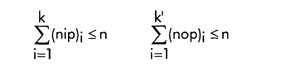
- the n input ports IP1, ..., IPn and splitter 11 are also part of input stage 41.
- the n output ports n OP1, ..., OPn and multiplexer 12 are part of output stage 43.
- Clock 41 gives the clock frequency for the data packet switching node.
- each segment is virtually divided in n equally long parts called words in the following, a clock period corresponding to the time needed to write a word in an input queue.
- the memory contains enough place for storing 32 segments.
- the segments received on input ports IP1, ..., IPn are synchronized so that the beginning of a segment received on input port IPi is delayed by one word (one clock period) compared to the beginning of the segment received on the previous input port IP(i-1).
- the available segment is stored in at location i of buffer memory 42.
- Figure 5 represents the contents of the buffer memory storing the segments of a packet comprising twelve segments a to I received on input interface II1.
- This way of storing the segments in buffer memory 42 enables it to easily retrieve an implicit link between all segments of a packet.
- figure 4 is further described.
- the control plane CP comprises a translation table 45 and a traffic management module 46 comprising k' control queues (each one associated to an output interface) 461, ..., 46k'.
- Translation table 45 contains routing information that is to say to which output interface(s) the packets arriving on an input interface should be switched to. Translation table 45 is preferably able to control the switching for several virtual connections on one input/output port simultaneously.
- translation table 45 determines the type of switching that is to be performed. Possible alternatives are point to point switching, point to multipoint switching or multi point to point switching.
- translation table 45 indicates that input interface II1 should be switched to output interface OI1. It is, however, not necessary to switch an input interface with a bit rate k*B to an output interface with the same bit rate.
- Other routing combinations known by a person skilled in the art are also supported by the present invention.
- Translation table 45 comprises also a mapping, stored in a first memory location, between the input ports IP1, ..., IPn and their corresponding input interface II1, ..., Ilk.
- translation table comprises a mapping, stored in a second memory location, between the output ports OP1, ..., OPn and their corresponding output interface OI1, ..., OIk'.
- Traffic management module 46 is responsible for controlling the retransmission of a packet stored in the memory buffer 42 on an output interface OI1, ..., Olk'. Traffic management module 46 controls the provision of quality of service requirements for the different packets. To each output interface are associated as many control queues as available quality of services. In this example and for sake of simplicity, it will be assumed that all packets require the same quality of service and as a consequence only one control queue 461, ..., 46k' is associated to one output interface OI1, ..., Olk'.
- Each entry in the control queue 46i indicates to output stage 43 the location in buffer memory 42 of the first segment of a packet to be retransmitted on output interface Oli.
- Translation table 45 comprises as well the number of consecutive segments belonging to the same packet to be switched on output interface OP1.
- control queues 461, ..., 46k' are successively and cyclically checked by output stage 43. Depending on the number of output ports associated to an output interface, the corresponding control queue will be checked by output stage 43 during the same number of clock periods.
- output interface OI1 corresponds to four output ports OP1, ..., OP4, then the control queue 461 will be checked for four clock periods before control queue 462 is checked for one clock period and so on.
- Control queues 461, ..., 46k' are handled with the FIFO (First In First Out) principle. At each clock period the next control queue is checked by output stage 43. If the transmission of a packet has been started and not completed, it is the task of output stage 43 to retrieve in buffer memory 42 the subsequent segment of this packet. This mechanism will be described in the following. No entry is read out of the control queue and output stage 43 jump to the next control queue for the next clock period.
- FIFO First In First Out
- output stage 43 checks the control queue and read the address of the first segment of a new packet to be retransmitted of buffer memory 42.
- output stage 43 It is also the role of output stage 43 to select the appropriate output ports OP1, ..., OP4 associated to output interface OI1 to retransmit the segments read out of buffer memory 42.
- the first segment is assigned randomly to one of the output ports associated to the output interface.
- Each subsequent segment is assigned to the next output port associated to the output interface.
- the output put is determined automatically from the value of the clock.
- Output interface associated to one output port Output interface associated to k>1 output port Input interface associated to one input port Address of previous segment sent on this port +n Address of previous segment sent on this port +k*n Input interface associated to k>1 input ports Address of the previous segment on this port +1 (if previous segment sent on this port was received on input port 1 to k-1) Address of the previous segment sent on this port +n Address of the previous segment on this port + n-k+1 (if previous segment sent on this port was received on input port k)
- Output interface 461 associated to one output port Output interface 461 associated to k> 1 output ports Input interface associated to one input port Address of previous segment retransmitted on this port +n Address of previous segment retransmitted on this port +n Input interface associated to k>1 input ports If previous segment received on input port 1 to k-1 Address of the previous segment on this port + 1 If previous segment received on input port k Address of the previous segment on this port + n-k+1
- the address of the segment to be retransmitted on this port is to be read in the control queue 461. It is the address of the first segment of a new packet).
- the association input ports/input interface, output ports/output interface as well as the number of input interfaces, resp. output interfaces, should be dynamically configurable according to the needs of the data packet switching node.
Landscapes
- Engineering & Computer Science (AREA)
- Computer Networks & Wireless Communication (AREA)
- Signal Processing (AREA)
- Data Exchanges In Wide-Area Networks (AREA)
- Communication Control (AREA)
Abstract
Description
- Figure 1 shows an embodiment of a data packet switching node according to the present invention;
- Figure 2 shows an example of inverse multiplexing on an input interface (Ingress Line);
- Figure 3 represents an example of multiplexing on an output interface (Egress Line);
- Figure 4 shows a bloc diagram of a data packet switching node according to the invention;
- Figure 5 represents the contents of the buffer memory storing the segments of a packet received on a very high speed interface.
| Output interface associated to one output port | Output interface associated to k>1 output port | |
| Input interface associated to one input port | Address of previous segment sent on this port +n | Address of previous segment sent on this port +k*n |
| Input interface associated to k>1 input ports | Address of the previous segment on this port +1 (if previous segment sent on this port was received on input port 1 to k-1) | Address of the previous segment sent on this port +n |
| Address of the previous segment on this port + n-k+1 (if previous segment sent on this port was received on input port k) |
| | Output interface | 461 associated to k> 1 output ports | |
| Input interface associated to one input port | Address of previous segment retransmitted on this port +n | Address of previous segment retransmitted on this port +n | |
| Input interface associated to k>1 input ports | If previous segment received on input port 1 to k-1 | Address of the previous segment on this port + 1 | |
| If previous segment received on input port k | Address of the previous segment on this port + n-k+1 |
Claims (7)
- A data packet switching node to be used in an asynchronous digital network, comprising:characterized in thatan input stage (41), cutting data packets into segments of constant length,a switching matrix (42, 45, 46) for switching, said switching matrix having input ports (IP1, ..., IPn) and output ports (OP1, ..., OPn) supporting identical bit rates B;and an output stage (43) reconstructing said data packets from said segments supplied by said output ports (OP1, ..., OPn) of said switching matrix,said input stage (41) comprises at least one input interface (II1, ..., Ilk) with a bit rate equal to a multiple of B, ki*B, and means (1 1 ) for splitting data packets received on said interface into segments distributed to ki input ports of said switching matrix;said output stage (43) comprises at least one output interface (OI1, ..., Olk') with a bit rate equal to a multiple of B, ko*B, and means for reconstructing a data packet with a bit rate equal to ko*B by concatenating segments supplied by ko output ports of said switching matrix; andki*ko>1.
- A data packet switching node according to claim 1, characterized in that said switching matrix comprises:a first memory location for storing an identifier representing the association between said input interface and said corresponding ki input ports;a second memory location for storing an identifier representing the association between said output interface and said corresponding ko output ports.
- A data packet switching node according to claim 1, characterized in that said switching matrix comprisesa buffer memory (42) for storing segments belonging to a packet received at said input interface (II1),memory writing means for sequentially writing segments received on said ki input ports (IP1, ..., IP4) in said buffer memory (42);a translation table (45) for determining the output interface (OI1) to which said segments belonging to said packet must be switched;a traffic management module (46) for storing the address of the first segment of said packet in said buffer memory (42),memory reading means for retrieving consecutive segments belonging to said packet in said buffer memory and cyclically assigning each of said segments to one of said ko output ports (OP1, ..., OP4) associated to said output interface (OI1).
- A data packet switching node according to claim 1, characterized in that it is dedicated to be used in an ATM switch to switch fixed length data packets supplied on said input interface.
- A data packet switching node according to claim 1, characterized in that it is dedicated to be used in an IP router to switch variable length data packets supplied on said input interface.
- A data packet switching node according to claim 1, characterized in that it is dedicated to be used in an equipment providing both IP routing and ATM switching functions.
- A data packet switching node according to claim 2, characterized in that the association between each input interface and corresponding input ports, as well as the association between each output interface and corresponding output ports are dynamically configurable in said first and second memory location.
Priority Applications (6)
| Application Number | Priority Date | Filing Date | Title |
|---|---|---|---|
| EP00440281A EP1199850B1 (en) | 2000-10-18 | 2000-10-18 | A data packet switching node accommodating very high bit rate interfaces |
| AT00440281T ATE404000T1 (en) | 2000-10-18 | 2000-10-18 | DATA PACKET SWITCHING NODE TO ACCOMMODATE VERY HIGH BIT RATE INTERFACES |
| DE60039764T DE60039764D1 (en) | 2000-10-18 | 2000-10-18 | Data packet switching node for receiving very high-bit-rate interfaces |
| JP2001314906A JP2002158713A (en) | 2000-10-18 | 2001-10-12 | Data packet switching node for very high bit rate interfaces |
| US09/975,961 US7068653B2 (en) | 2000-10-18 | 2001-10-15 | Data packet switching node accommodating very high bit rate interfaces |
| CN01137004.1A CN1200542C (en) | 2000-10-18 | 2001-10-18 | Data packet switching node having super high bit rate interface |
Applications Claiming Priority (1)
| Application Number | Priority Date | Filing Date | Title |
|---|---|---|---|
| EP00440281A EP1199850B1 (en) | 2000-10-18 | 2000-10-18 | A data packet switching node accommodating very high bit rate interfaces |
Publications (2)
| Publication Number | Publication Date |
|---|---|
| EP1199850A1 true EP1199850A1 (en) | 2002-04-24 |
| EP1199850B1 EP1199850B1 (en) | 2008-08-06 |
Family
ID=8174174
Family Applications (1)
| Application Number | Title | Priority Date | Filing Date |
|---|---|---|---|
| EP00440281A Expired - Lifetime EP1199850B1 (en) | 2000-10-18 | 2000-10-18 | A data packet switching node accommodating very high bit rate interfaces |
Country Status (6)
| Country | Link |
|---|---|
| US (1) | US7068653B2 (en) |
| EP (1) | EP1199850B1 (en) |
| JP (1) | JP2002158713A (en) |
| CN (1) | CN1200542C (en) |
| AT (1) | ATE404000T1 (en) |
| DE (1) | DE60039764D1 (en) |
Cited By (1)
| Publication number | Priority date | Publication date | Assignee | Title |
|---|---|---|---|---|
| EP1738267A4 (en) * | 2004-03-18 | 2008-01-09 | Micron Technology Inc | System and method for organizing data transfers with memory hub memory modules |
Families Citing this family (9)
| Publication number | Priority date | Publication date | Assignee | Title |
|---|---|---|---|---|
| US7366166B2 (en) * | 2003-04-25 | 2008-04-29 | Alcatel Usa Sourcing, L.P. | Data switching using soft configuration |
| US7542464B2 (en) * | 2003-05-14 | 2009-06-02 | Fraser Alexander G | Switching network |
| ITMI20031309A1 (en) * | 2003-06-26 | 2004-12-27 | Marconi Comm Spa | SWITCHING NETWORK. |
| JP4432388B2 (en) * | 2003-08-12 | 2010-03-17 | 株式会社日立製作所 | Input/Output Control Unit |
| JP4360300B2 (en) * | 2004-08-10 | 2009-11-11 | 富士通株式会社 | Storage control device and control method |
| US7672304B2 (en) * | 2005-06-16 | 2010-03-02 | Samsung Electronics Co., Ltd. | Method and system for switching frames in a switching system |
| US20080159190A1 (en) * | 2006-12-28 | 2008-07-03 | Mediatek Inc. | Wireless Transmission Method, Apparatus, And System |
| US20100103914A1 (en) * | 2006-12-28 | 2010-04-29 | Mediatek Inc. | Wireless Transmission Method, Apparatus, And System |
| CN104468416A (en) * | 2014-11-21 | 2015-03-25 | 天津光电通信技术有限公司 | Method for obtaining crossing system of radio-frequency switching matrix |
Citations (2)
| Publication number | Priority date | Publication date | Assignee | Title |
|---|---|---|---|---|
| US5440550A (en) * | 1991-07-01 | 1995-08-08 | Telstra Corporation Limited | High speed switching architecture |
| US5905725A (en) * | 1996-12-16 | 1999-05-18 | Juniper Networks | High speed switching device |
Family Cites Families (4)
| Publication number | Priority date | Publication date | Assignee | Title |
|---|---|---|---|---|
| US5365519A (en) * | 1991-03-05 | 1994-11-15 | Hitachi, Ltd. | ATM switch1ng system connectable to I/O links having different transmission rates |
| FR2660818B1 (en) | 1990-04-06 | 1992-06-19 | France Telecom | FRAME SWITCHER FOR ASYNCHRONOUS DIGITAL NETWORK. |
| EP0706297A1 (en) * | 1994-10-07 | 1996-04-10 | International Business Machines Corporation | Method for operating traffic congestion control in a data communication network and system for implementing said method |
| US6351466B1 (en) * | 1998-05-01 | 2002-02-26 | Hewlett-Packard Company | Switching systems and methods of operation of switching systems |
-
2000
- 2000-10-18 DE DE60039764T patent/DE60039764D1/en not_active Expired - Lifetime
- 2000-10-18 EP EP00440281A patent/EP1199850B1/en not_active Expired - Lifetime
- 2000-10-18 AT AT00440281T patent/ATE404000T1/en not_active IP Right Cessation
-
2001
- 2001-10-12 JP JP2001314906A patent/JP2002158713A/en active Pending
- 2001-10-15 US US09/975,961 patent/US7068653B2/en not_active Expired - Fee Related
- 2001-10-18 CN CN01137004.1A patent/CN1200542C/en not_active Expired - Fee Related
Patent Citations (2)
| Publication number | Priority date | Publication date | Assignee | Title |
|---|---|---|---|---|
| US5440550A (en) * | 1991-07-01 | 1995-08-08 | Telstra Corporation Limited | High speed switching architecture |
| US5905725A (en) * | 1996-12-16 | 1999-05-18 | Juniper Networks | High speed switching device |
Non-Patent Citations (1)
| Title |
|---|
| CHIUSSI F M ET AL: "GENERALIZED INVERSE MULTIPLEXING OF SWITCHED ATM CONNECTIONS", IEEE GLOBAL TELECOMMUNICATIONS CONFERENCE,US,NEW YORK, NY: IEEE, 1998, pages 3134 - 3140, XP000801610, ISBN: 0-7803-4985-7 * |
Cited By (2)
| Publication number | Priority date | Publication date | Assignee | Title |
|---|---|---|---|---|
| EP1738267A4 (en) * | 2004-03-18 | 2008-01-09 | Micron Technology Inc | System and method for organizing data transfers with memory hub memory modules |
| KR100840140B1 (en) * | 2004-03-18 | 2008-06-23 | 마이크론 테크놀로지 인코포레이티드 | System and method for organizing data transfers using memory hub memory modules |
Also Published As
| Publication number | Publication date |
|---|---|
| US20020064162A1 (en) | 2002-05-30 |
| EP1199850B1 (en) | 2008-08-06 |
| CN1349334A (en) | 2002-05-15 |
| CN1200542C (en) | 2005-05-04 |
| ATE404000T1 (en) | 2008-08-15 |
| JP2002158713A (en) | 2002-05-31 |
| DE60039764D1 (en) | 2008-09-18 |
| US7068653B2 (en) | 2006-06-27 |
Similar Documents
| Publication | Publication Date | Title |
|---|---|---|
| US6463057B1 (en) | ATM cell switching system | |
| US5555256A (en) | Channel identifier generation | |
| EP0471344A1 (en) | Traffic shaping method and circuit | |
| US4797880A (en) | Non-blocking, self-routing packet switch | |
| US20050008025A1 (en) | Router apparatus using ATM switch | |
| JPH06261058A (en) | Common memory switch and switching method for routing digital information signal | |
| US6931002B1 (en) | Hybrid switching | |
| CN1120877A (en) | message routing | |
| JPH10117200A (en) | Switch, cross-connect switching device, connection device, and routing method in switch | |
| EP1199850A1 (en) | A data packet switching node accommodating very high bit rate interfaces | |
| JP2741864B2 (en) | Switching network control method and circuit arrangement | |
| JP4484990B2 (en) | Optical fiber delay line buffer with gap filling | |
| EP0683949B1 (en) | A method for handling redundant switching planes in packet switches and a switch for carrying out the method | |
| US6775294B2 (en) | Time slot assigner for communication system | |
| KR100688734B1 (en) | Method for operating communication channel synchronous cell system and communication channel synchronous cell system | |
| US7046660B2 (en) | Switching apparatus for high speed channels using multiple parallel lower speed channels while maintaining data rate | |
| US8031723B2 (en) | Centralized switching and routing packet handling device | |
| US20010028652A1 (en) | ATM cell switching system | |
| AU622948B2 (en) | Packet switch converter | |
| US6980545B1 (en) | Apparatus for routing asynchronous traffic in a circuit switched network | |
| JP2002344514A (en) | Multicast method and multicast device | |
| CA2109007C (en) | Time slot assigner for communication system | |
| JP2754612B2 (en) | Packet switch | |
| US6330240B1 (en) | ATM cell switching system | |
| JPH1174892A (en) | Cell switchboard |
Legal Events
| Date | Code | Title | Description |
|---|---|---|---|
| PUAI | Public reference made under article 153(3) epc to a published international application that has entered the european phase |
Free format text: ORIGINAL CODE: 0009012 |
|
| AK | Designated contracting states |
Kind code of ref document: A1 Designated state(s): AT BE CH CY DE DK ES FI FR GB GR IE IT LI LU MC NL PT SE |
|
| AX | Request for extension of the european patent |
Free format text: AL;LT;LV;MK;RO;SI |
|
| 17P | Request for examination filed |
Effective date: 20020730 |
|
| AKX | Designation fees paid |
Free format text: AT BE CH CY DE DK ES FI FR GB GR IE IT LI LU MC NL PT SE |
|
| 17Q | First examination report despatched |
Effective date: 20060406 |
|
| RAP1 | Party data changed (applicant data changed or rights of an application transferred) |
Owner name: ALCATEL LUCENT |
|
| GRAP | Despatch of communication of intention to grant a patent |
Free format text: ORIGINAL CODE: EPIDOSNIGR1 |
|
| GRAS | Grant fee paid |
Free format text: ORIGINAL CODE: EPIDOSNIGR3 |
|
| GRAA | (expected) grant |
Free format text: ORIGINAL CODE: 0009210 |
|
| AK | Designated contracting states |
Kind code of ref document: B1 Designated state(s): AT BE CH CY DE DK ES FI FR GB GR IE IT LI LU MC NL PT SE |
|
| REG | Reference to a national code |
Ref country code: GB Ref legal event code: FG4D |
|
| REG | Reference to a national code |
Ref country code: CH Ref legal event code: EP |
|
| REG | Reference to a national code |
Ref country code: IE Ref legal event code: FG4D |
|
| REF | Corresponds to: |
Ref document number: 60039764 Country of ref document: DE Date of ref document: 20080918 Kind code of ref document: P |
|
| PG25 | Lapsed in a contracting state [announced via postgrant information from national office to epo] |
Ref country code: NL Free format text: LAPSE BECAUSE OF FAILURE TO SUBMIT A TRANSLATION OF THE DESCRIPTION OR TO PAY THE FEE WITHIN THE PRESCRIBED TIME-LIMIT Effective date: 20080806 Ref country code: ES Free format text: LAPSE BECAUSE OF FAILURE TO SUBMIT A TRANSLATION OF THE DESCRIPTION OR TO PAY THE FEE WITHIN THE PRESCRIBED TIME-LIMIT Effective date: 20081117 |
|
| PG25 | Lapsed in a contracting state [announced via postgrant information from national office to epo] |
Ref country code: AT Free format text: LAPSE BECAUSE OF FAILURE TO SUBMIT A TRANSLATION OF THE DESCRIPTION OR TO PAY THE FEE WITHIN THE PRESCRIBED TIME-LIMIT Effective date: 20080806 Ref country code: FI Free format text: LAPSE BECAUSE OF FAILURE TO SUBMIT A TRANSLATION OF THE DESCRIPTION OR TO PAY THE FEE WITHIN THE PRESCRIBED TIME-LIMIT Effective date: 20080806 |
|
| PG25 | Lapsed in a contracting state [announced via postgrant information from national office to epo] |
Ref country code: BE Free format text: LAPSE BECAUSE OF FAILURE TO SUBMIT A TRANSLATION OF THE DESCRIPTION OR TO PAY THE FEE WITHIN THE PRESCRIBED TIME-LIMIT Effective date: 20080806 |
|
| PG25 | Lapsed in a contracting state [announced via postgrant information from national office to epo] |
Ref country code: DK Free format text: LAPSE BECAUSE OF FAILURE TO SUBMIT A TRANSLATION OF THE DESCRIPTION OR TO PAY THE FEE WITHIN THE PRESCRIBED TIME-LIMIT Effective date: 20080806 |
|
| PG25 | Lapsed in a contracting state [announced via postgrant information from national office to epo] |
Ref country code: MC Free format text: LAPSE BECAUSE OF NON-PAYMENT OF DUE FEES Effective date: 20081031 Ref country code: PT Free format text: LAPSE BECAUSE OF FAILURE TO SUBMIT A TRANSLATION OF THE DESCRIPTION OR TO PAY THE FEE WITHIN THE PRESCRIBED TIME-LIMIT Effective date: 20090106 |
|
| REG | Reference to a national code |
Ref country code: CH Ref legal event code: PL |
|
| PLBE | No opposition filed within time limit |
Free format text: ORIGINAL CODE: 0009261 |
|
| STAA | Information on the status of an ep patent application or granted ep patent |
Free format text: STATUS: NO OPPOSITION FILED WITHIN TIME LIMIT |
|
| 26N | No opposition filed |
Effective date: 20090507 |
|
| PG25 | Lapsed in a contracting state [announced via postgrant information from national office to epo] |
Ref country code: IT Free format text: LAPSE BECAUSE OF FAILURE TO SUBMIT A TRANSLATION OF THE DESCRIPTION OR TO PAY THE FEE WITHIN THE PRESCRIBED TIME-LIMIT Effective date: 20080806 |
|
| PG25 | Lapsed in a contracting state [announced via postgrant information from national office to epo] |
Ref country code: IE Free format text: LAPSE BECAUSE OF NON-PAYMENT OF DUE FEES Effective date: 20081018 Ref country code: LI Free format text: LAPSE BECAUSE OF NON-PAYMENT OF DUE FEES Effective date: 20081031 Ref country code: CH Free format text: LAPSE BECAUSE OF NON-PAYMENT OF DUE FEES Effective date: 20081031 |
|
| PG25 | Lapsed in a contracting state [announced via postgrant information from national office to epo] |
Ref country code: SE Free format text: LAPSE BECAUSE OF FAILURE TO SUBMIT A TRANSLATION OF THE DESCRIPTION OR TO PAY THE FEE WITHIN THE PRESCRIBED TIME-LIMIT Effective date: 20081106 |
|
| PG25 | Lapsed in a contracting state [announced via postgrant information from national office to epo] |
Ref country code: LU Free format text: LAPSE BECAUSE OF NON-PAYMENT OF DUE FEES Effective date: 20081018 Ref country code: CY Free format text: LAPSE BECAUSE OF FAILURE TO SUBMIT A TRANSLATION OF THE DESCRIPTION OR TO PAY THE FEE WITHIN THE PRESCRIBED TIME-LIMIT Effective date: 20080806 |
|
| PG25 | Lapsed in a contracting state [announced via postgrant information from national office to epo] |
Ref country code: GR Free format text: LAPSE BECAUSE OF FAILURE TO SUBMIT A TRANSLATION OF THE DESCRIPTION OR TO PAY THE FEE WITHIN THE PRESCRIBED TIME-LIMIT Effective date: 20081107 |
|
| REG | Reference to a national code |
Ref country code: FR Ref legal event code: GC Effective date: 20131018 |
|
| REG | Reference to a national code |
Ref country code: FR Ref legal event code: RG Effective date: 20141016 |
|
| REG | Reference to a national code |
Ref country code: FR Ref legal event code: CA Effective date: 20150521 |
|
| REG | Reference to a national code |
Ref country code: FR Ref legal event code: CA Effective date: 20150521 |
|
| REG | Reference to a national code |
Ref country code: FR Ref legal event code: PLFP Year of fee payment: 16 |
|
| REG | Reference to a national code |
Ref country code: FR Ref legal event code: PLFP Year of fee payment: 17 |
|
| REG | Reference to a national code |
Ref country code: FR Ref legal event code: PLFP Year of fee payment: 18 |
|
| PGFP | Annual fee paid to national office [announced via postgrant information from national office to epo] |
Ref country code: FR Payment date: 20171024 Year of fee payment: 18 Ref country code: DE Payment date: 20171019 Year of fee payment: 18 |
|
| PGFP | Annual fee paid to national office [announced via postgrant information from national office to epo] |
Ref country code: GB Payment date: 20171019 Year of fee payment: 18 |
|
| REG | Reference to a national code |
Ref country code: DE Ref legal event code: R119 Ref document number: 60039764 Country of ref document: DE |
|
| GBPC | Gb: european patent ceased through non-payment of renewal fee |
Effective date: 20181018 |
|
| PG25 | Lapsed in a contracting state [announced via postgrant information from national office to epo] |
Ref country code: DE Free format text: LAPSE BECAUSE OF NON-PAYMENT OF DUE FEES Effective date: 20190501 |
|
| PG25 | Lapsed in a contracting state [announced via postgrant information from national office to epo] |
Ref country code: FR Free format text: LAPSE BECAUSE OF NON-PAYMENT OF DUE FEES Effective date: 20181031 |
|
| PG25 | Lapsed in a contracting state [announced via postgrant information from national office to epo] |
Ref country code: GB Free format text: LAPSE BECAUSE OF NON-PAYMENT OF DUE FEES Effective date: 20181018 |