EP1199583A2 - Optical fiber dispersion equalizer - Google Patents
Optical fiber dispersion equalizer Download PDFInfo
- Publication number
- EP1199583A2 EP1199583A2 EP01117343A EP01117343A EP1199583A2 EP 1199583 A2 EP1199583 A2 EP 1199583A2 EP 01117343 A EP01117343 A EP 01117343A EP 01117343 A EP01117343 A EP 01117343A EP 1199583 A2 EP1199583 A2 EP 1199583A2
- Authority
- EP
- European Patent Office
- Prior art keywords
- optical fiber
- heaters
- light
- grating
- temperature
- Prior art date
- Legal status (The legal status is an assumption and is not a legal conclusion. Google has not performed a legal analysis and makes no representation as to the accuracy of the status listed.)
- Withdrawn
Links
Images





Classifications
-
- H—ELECTRICITY
- H04—ELECTRIC COMMUNICATION TECHNIQUE
- H04B—TRANSMISSION
- H04B10/00—Transmission systems employing electromagnetic waves other than radio-waves, e.g. infrared, visible or ultraviolet light, or employing corpuscular radiation, e.g. quantum communication
- H04B10/25—Arrangements specific to fibre transmission
- H04B10/2507—Arrangements specific to fibre transmission for the reduction or elimination of distortion or dispersion
-
- G—PHYSICS
- G02—OPTICS
- G02B—OPTICAL ELEMENTS, SYSTEMS OR APPARATUS
- G02B6/00—Light guides; Structural details of arrangements comprising light guides and other optical elements, e.g. couplings
- G02B6/24—Coupling light guides
- G02B6/26—Optical coupling means
- G02B6/28—Optical coupling means having data bus means, i.e. plural waveguides interconnected and providing an inherently bidirectional system by mixing and splitting signals
- G02B6/293—Optical coupling means having data bus means, i.e. plural waveguides interconnected and providing an inherently bidirectional system by mixing and splitting signals with wavelength selective means
- G02B6/29304—Optical coupling means having data bus means, i.e. plural waveguides interconnected and providing an inherently bidirectional system by mixing and splitting signals with wavelength selective means operating by diffraction, e.g. grating
- G02B6/29316—Light guides comprising a diffractive element, e.g. grating in or on the light guide such that diffracted light is confined in the light guide
- G02B6/29317—Light guides of the optical fibre type
- G02B6/29322—Diffractive elements of the tunable type
-
- G—PHYSICS
- G02—OPTICS
- G02B—OPTICAL ELEMENTS, SYSTEMS OR APPARATUS
- G02B6/00—Light guides; Structural details of arrangements comprising light guides and other optical elements, e.g. couplings
- G02B6/02—Optical fibres with cladding with or without a coating
- G02B6/02057—Optical fibres with cladding with or without a coating comprising gratings
- G02B6/02076—Refractive index modulation gratings, e.g. Bragg gratings
- G02B6/02195—Refractive index modulation gratings, e.g. Bragg gratings characterised by means for tuning the grating
- G02B6/02204—Refractive index modulation gratings, e.g. Bragg gratings characterised by means for tuning the grating using thermal effects, e.g. heating or cooling of a temperature sensitive mounting body
-
- G—PHYSICS
- G02—OPTICS
- G02B—OPTICAL ELEMENTS, SYSTEMS OR APPARATUS
- G02B6/00—Light guides; Structural details of arrangements comprising light guides and other optical elements, e.g. couplings
- G02B6/24—Coupling light guides
- G02B6/26—Optical coupling means
- G02B6/28—Optical coupling means having data bus means, i.e. plural waveguides interconnected and providing an inherently bidirectional system by mixing and splitting signals
- G02B6/293—Optical coupling means having data bus means, i.e. plural waveguides interconnected and providing an inherently bidirectional system by mixing and splitting signals with wavelength selective means
- G02B6/29379—Optical coupling means having data bus means, i.e. plural waveguides interconnected and providing an inherently bidirectional system by mixing and splitting signals with wavelength selective means characterised by the function or use of the complete device
- G02B6/29392—Controlling dispersion
- G02B6/29394—Compensating wavelength dispersion
-
- G—PHYSICS
- G02—OPTICS
- G02B—OPTICAL ELEMENTS, SYSTEMS OR APPARATUS
- G02B6/00—Light guides; Structural details of arrangements comprising light guides and other optical elements, e.g. couplings
- G02B6/24—Coupling light guides
- G02B6/26—Optical coupling means
- G02B6/28—Optical coupling means having data bus means, i.e. plural waveguides interconnected and providing an inherently bidirectional system by mixing and splitting signals
- G02B6/293—Optical coupling means having data bus means, i.e. plural waveguides interconnected and providing an inherently bidirectional system by mixing and splitting signals with wavelength selective means
- G02B6/29379—Optical coupling means having data bus means, i.e. plural waveguides interconnected and providing an inherently bidirectional system by mixing and splitting signals with wavelength selective means characterised by the function or use of the complete device
- G02B6/29395—Optical coupling means having data bus means, i.e. plural waveguides interconnected and providing an inherently bidirectional system by mixing and splitting signals with wavelength selective means characterised by the function or use of the complete device configurable, e.g. tunable or reconfigurable
-
- G—PHYSICS
- G02—OPTICS
- G02F—OPTICAL DEVICES OR ARRANGEMENTS FOR THE CONTROL OF LIGHT BY MODIFICATION OF THE OPTICAL PROPERTIES OF THE MEDIA OF THE ELEMENTS INVOLVED THEREIN; NON-LINEAR OPTICS; FREQUENCY-CHANGING OF LIGHT; OPTICAL LOGIC ELEMENTS; OPTICAL ANALOGUE/DIGITAL CONVERTERS
- G02F1/00—Devices or arrangements for the control of the intensity, colour, phase, polarisation or direction of light arriving from an independent light source, e.g. switching, gating or modulating; Non-linear optics
- G02F1/01—Devices or arrangements for the control of the intensity, colour, phase, polarisation or direction of light arriving from an independent light source, e.g. switching, gating or modulating; Non-linear optics for the control of the intensity, phase, polarisation or colour
- G02F1/011—Devices or arrangements for the control of the intensity, colour, phase, polarisation or direction of light arriving from an independent light source, e.g. switching, gating or modulating; Non-linear optics for the control of the intensity, phase, polarisation or colour in optical waveguides, not otherwise provided for in this subclass
- G02F1/0115—Devices or arrangements for the control of the intensity, colour, phase, polarisation or direction of light arriving from an independent light source, e.g. switching, gating or modulating; Non-linear optics for the control of the intensity, phase, polarisation or colour in optical waveguides, not otherwise provided for in this subclass in optical fibres
-
- H—ELECTRICITY
- H04—ELECTRIC COMMUNICATION TECHNIQUE
- H04B—TRANSMISSION
- H04B10/00—Transmission systems employing electromagnetic waves other than radio-waves, e.g. infrared, visible or ultraviolet light, or employing corpuscular radiation, e.g. quantum communication
- H04B10/25—Arrangements specific to fibre transmission
-
- G—PHYSICS
- G02—OPTICS
- G02B—OPTICAL ELEMENTS, SYSTEMS OR APPARATUS
- G02B6/00—Light guides; Structural details of arrangements comprising light guides and other optical elements, e.g. couplings
- G02B6/24—Coupling light guides
- G02B6/26—Optical coupling means
- G02B6/28—Optical coupling means having data bus means, i.e. plural waveguides interconnected and providing an inherently bidirectional system by mixing and splitting signals
- G02B6/293—Optical coupling means having data bus means, i.e. plural waveguides interconnected and providing an inherently bidirectional system by mixing and splitting signals with wavelength selective means
- G02B6/29379—Optical coupling means having data bus means, i.e. plural waveguides interconnected and providing an inherently bidirectional system by mixing and splitting signals with wavelength selective means characterised by the function or use of the complete device
- G02B6/29398—Temperature insensitivity
-
- G—PHYSICS
- G02—OPTICS
- G02F—OPTICAL DEVICES OR ARRANGEMENTS FOR THE CONTROL OF LIGHT BY MODIFICATION OF THE OPTICAL PROPERTIES OF THE MEDIA OF THE ELEMENTS INVOLVED THEREIN; NON-LINEAR OPTICS; FREQUENCY-CHANGING OF LIGHT; OPTICAL LOGIC ELEMENTS; OPTICAL ANALOGUE/DIGITAL CONVERTERS
- G02F1/00—Devices or arrangements for the control of the intensity, colour, phase, polarisation or direction of light arriving from an independent light source, e.g. switching, gating or modulating; Non-linear optics
- G02F1/01—Devices or arrangements for the control of the intensity, colour, phase, polarisation or direction of light arriving from an independent light source, e.g. switching, gating or modulating; Non-linear optics for the control of the intensity, phase, polarisation or colour
- G02F1/0147—Devices or arrangements for the control of the intensity, colour, phase, polarisation or direction of light arriving from an independent light source, e.g. switching, gating or modulating; Non-linear optics for the control of the intensity, phase, polarisation or colour based on thermo-optic effects
-
- G—PHYSICS
- G02—OPTICS
- G02F—OPTICAL DEVICES OR ARRANGEMENTS FOR THE CONTROL OF LIGHT BY MODIFICATION OF THE OPTICAL PROPERTIES OF THE MEDIA OF THE ELEMENTS INVOLVED THEREIN; NON-LINEAR OPTICS; FREQUENCY-CHANGING OF LIGHT; OPTICAL LOGIC ELEMENTS; OPTICAL ANALOGUE/DIGITAL CONVERTERS
- G02F2201/00—Constructional arrangements not provided for in groups G02F1/00 - G02F7/00
- G02F2201/30—Constructional arrangements not provided for in groups G02F1/00 - G02F7/00 grating
- G02F2201/307—Reflective grating, i.e. Bragg grating
Definitions
- the present invention relates to a light dispersion compensation technique for light signals transmitted at a high speed through an optical fiber in an optical fiber communication system.
- the propagating rate of light signals in a transmitting path varies according to wavelength. This variation exists because the refractive index of transmitting mediums differs for different wavelengths. In an optical transmitting path represented by an optical fiber, because light is confined in the transmitting medium for transmission, the transmitting rate of a signal will vary when the wavelength varies. This variation in transmitting rate according to wavelengths is know as dispersion, and a value for dispersion is given as a differential when delay time is expressed as a function of the wavelength.
- the phenomenon of dispersion is inevitable in high-speed optical transmission, and causes deterioration of waveform of the signal in transmission. Therefore, for long distance transmission of the light signals, compensation for the dispersion is indispensable, and a technique for the compensation is called light dispersion compensation, or light dispersion equalization.
- a light dispersion compensating device a light dispersion compensating fiber (hereinafter referred to as DCF), or a variable light dispersion equalizer for micro-adjustment is used.
- the DCF is a fiber-type device having a dispersion quantity of a code reverse to the dispersion occurred in the transmission path, and matches a fiber length with the dispersion quantity generated in the transmission path for adjustment of the compensation quantity. At that point, because the dispersion quantity the DCF compensates is a fixed value, the variable type light dispersion equalizer which can finely control the dispersion compensation quantity is used for small scale variations in the dispersion quantity accompanied to changes in a usage condition.
- a fiber grating type variable light dispersion equalizer which is common in the above-described variable type light dispersion equalizer, is described.
- a core optical waveguide
- a diffraction grating which is a core refractive index varied by Bragg wavelength period and is called a grating
- the Bragg wavelength ( ⁇ B) is a wavelength reflected at the grating, and is expressed by the following expression (1) by an interval of the grating ( ⁇ ) and equivalent refractive index (Neff) of the grating.
- ⁇ B 2 ⁇ Neff ⁇
- the grating is a chirped grating in which an interval is linearly varied in the lengthwise direction of the optical waveguide, and the Bragg wavelength at this is linearly distributed in the lengthwise direction of the optical waveguide.
- This is equivalent to linear-functional distribution, in the lengthwise direction of the waveguide, of the reflecting point of light corresponded with each Bragg wavelength, and, because delay time is determined in accordance with a distance to the reflecting point, a delay quantity is expressed as a linear function of the wavelength.
- the dispersion quantity can be fixed by giving a longer distance to the reflecting point in the grating for a wavelength of which delay time in the transmitting path is smaller, by giving shorter distance to the reflecting point in the grating for a wavelength of which delay time is larger, and by linearly giving the delay quantity for the wavelength in a region therebetween.
- the equivalent refractive index (Neff) of the grating can also be written as a function of the temperature. Accordingly, when the temperature of the grating is changed to vary the Neff, the distance to the reflecting point in the grating can be controlled. According to this principle, when a temperature gradient to make a temperature difference ⁇ T is given to a grating unit, the distance to the reflecting point in the grating is linearly changed for the temperature and,thus, the dispersion quantity is changed.
- variable dispersion compensation when a temperature gradient is given to the grating in order to make the temperature difference ⁇ T variable, the dispersion quantity becomes controllable, and variable light dispersion compensation can be realized.
- an ideal temperature gradient in the variable dispersion compensation must have a linear gradient in which temperature change ratio is constant across the total length of the grating, and that conditions for an ideal heater comprises a plurality of heaters with smaller heating areas, larger number of heaters, and minimum gaps between the heaters. The more conditions can be made to approach the ideal, the more closely will the temperature gradient approximate a straight line.
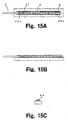
- Fig. 16A is a chart showing the relationship between the temperature of an optical fiber and positions of heaters under heating by the heaters in the light dispersion equalizer shown in Fig. 15, and Fig. 16B is a chart showing relationship between the dispersion quantity and the wavelength in a state shown in Fig. 16A.
- Fig. 14 is a block diagram showing a connecting state of the light dispersion equalizer with peripheral devices shown in Fig. 15.
- Fig. 15 shown are an optical fiber 1, heaters 3, a substrate 4, a chirped grating 27, a heater-1 28a, a heater-N 28b, and adhesive agents 29.
- Fig. 14 there are an optical fiber transmitting path 20, input signal light 21, signal light after dispersion and equalization 22, a light dispersion equalizer 23, an optical circulator 24, a heater control circuit 25, and an electric cable 26.
- the signal light 21 input through the optical fiber transmitting path 20 in Fig. 14 is reflected at a grating unit of the light dispersion equalizer 23, and output to a port set by the optical circulator 24 as signal light 22 in which the dispersion quantity is compensated.
- a heater of the light dispersion equalizer 23 is controlled by the control circuit 25, and the temperature gradient shown in Fig. 16 is given to the optical fiber. In this manner, variable control of the dispersion quantity shown in Fig. 16B can be realized.
- a plurality of heaters are arranged in a range exceeding the length of the grating of the optical fiber, thereby heat generating quantity of heaters is adjusted for each location such that a predetermined temperature gradient is given to the optical fiber.
- the temperature gradient of the optical fiber to be a desired dispersion quantity is derived from correlated value of the dispersion quantity and the temperature gradient of the optical fiber, and heat generating quantity of the heaters is matched with the predetermined quantity.
- the width of heaters formed on the substrate is made larger than the diameter of the optical fiber, and the optical fiber is adhered to and fixed on the heaters. Then, after the adhesive agent is hardened, the optical fiber is viewed to confirm that it does not protrude from the heaters. Accordingly, the heaters are made unnecessarily larger, causing a problem of increased power consumption.
- the width of the heaters is made narrower in order to reduce power consumption, the position of the optical fiber is liable to deviate from the heaters, thus lowering yielding in an adhesive agent hardening work.
- variations in heat transmission from the heaters results, thereby deteriorating dispersion compensation accuracy.
- An object of the present invention is to provide a light dispersion equalizer in which the positional relationship and connection state between an optical fiber and a heater are stabilized, power consumption is reduced, and dispersion control is stabilized.
- the plurality of heaters are arranged on the substrate along the groove.
- the light dispersion equalizer comprises an optical fiber having a grating for causing reflection of light of a predetermined wavelength from signal light propagated through the optical fiber, a holder having a groove for holding the optical fiber formed thereon, a plurality of heaters for regulating the temperature of the optical fiber, and a substrate having the plurality of heaters arranged thereon along the groove.
- the optical fiber is grasped by the holder and the substrate.
- the light dispersion equalizer comprises an optical fiber having a grating for causing reflection of light of a predetermined wavelength from signal light propagated through the optical fiber, a plurality of heaters for regulating the temperature of the optical fiber, and a substrate having the plurality of heaters thereon. On the substrate is a mark indicating a mounting position of the optical fiber, and the optical fiber is positioned by the mark and mounted on the heater.
- the heater has cross-sectional areas which vary in the axial direction of the optical fiber.
- the heater is obliquely arranged relative to an axis of the optical fiber on the substrate.
- the light dispersion equalizer according to sixth aspect of the present invention comprises an optical fiber having a grating for causing reflection of light of a predetermined wavelength from signal light propagated through the optical fiber, and heaters for regulating the temperature of the optical fiber.
- the heaters are arranged on an external periphery of the optical fiber.
- the light dispersion equalizer according to a seventh aspect of the present invention comprises an optical fiber having a grating for causing reflection of light of a predetermined wavelength from signal light propagated through the optical fiber and heaters for regulating the temperature of the optical fiber.
- the heaters are arranged on a plane formed on an external cladding periphery of the optical fiber.
- the light dispersion equalizer comprises an optical fiber having a grating for causing reflection of light of a predetermined wavelength from signal light propagated through the optical fiber, heaters for regulating the temperature of the optical fiber, and a substrate having the heater thereon. At ends of the heaters, tapered units are formed.
- the light dispersion equalizer comprises an optical fiber having a grating for causing reflection of light of a predetermined wavelength from signal light propagated through the optical fiber, a plurality of heaters for regulating the temperature of the optical fiber, and a substrate having the heaters thereon.
- the heaters include heat generators and tapered patterns connected with the heat generators, and the optical fiber is arranged on the heat generators.
- the light dispersion equalizer comprises an optical fiber having a grating for causing reflection of light of a predetermined wavelength from signal light propagated through the optical fiber, a plurality of heaters for regulating the temperature of the optical fiber, and variable resistors connected in series with the plurality of heaters, respectively.
- Figs. 1A-C illustrate a first embodiment of the present invention. Shown in Figs . 1A-C are an optical fiber 1 with a grating, a grating 2, heaters 3, a substrate 4, and an optical fiber accommodating groove 5.
- the heaters 3 are formed arranged in a row in a range longer than the grating at positions in parallel with the optical fiber accommodating groove 5, and the optical fiber 1 is mounted in the optical fiber accommodating groove 5 at a position where a grating unit is within a range of the heaters 3.
- the heaters 3 can be arranged opposing each other across the optical fiber accommodating groove 5, and, when this is done, the internal temperature of the optical fiber 1 can be stabilized because heat is transferred to the optical fiber 1 from two diametric locations. At this point, when the heaters 3 are formed on a surface of the optical fiber accommodating groove 5 where the optical fiber 1 contacts, the distance between the optical fiber 1 and the heaters 3 can be shortened, thus improving efficiency of the temperature control.
- the heaters 3 are controlled by a control circuit 25, and heat generating quantity of respective heaters is differentiated so that the temperature of the optical fiber 1 can have a temperature gradient as shown in Fig. 16A, thus achieving a variable control of the dispersion quantity as shown in Fig. 16B.
- Figs. 2A and 2B illustrate a configuration for an example according to a second embodiment of the present invention, showing an optical fiber 1 with a grating, heaters 3, a substrate 4, an optical fiber accommodating groove 5, a grooved cover 6, a first contact 7a, and second contacts 7b.
- the heaters 3 are arranged in a row for a range longer than the grating and in parallel with the first contact 7a, the optical fiber accommodating groove 5 is provided on the grooved cover 6 in parallel with the first contact 7a, the optical fiber 1 is mounted in the optical fiber accommodating groove 5, and the optical fiber 1 and the heaters 3 are positioned and fixed by the first contact 7a and second contacts 7b.
- the optical fiber 1 is mounted in an axial direction at a position such that the grating unit is within a range of the heaters 3. Because the parts on which the optical fiber 1 is mounted and parts on which the heaters are mounted are separated, the distance between the optical fiber 1 and the heaters 3 can be shortened. It should be noted that the controlling method for the dispersion characteristic is the same as for the first embodiment.
- the optical fiber and the heaters can be more closely positioned such that stable high heat conductive efficiency can be obtained, and such that power consumption can be reduced and response time improved.
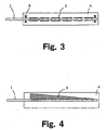
- Fig. 3 illustrates a configuration according to a third embodiment of the present invention.
- an optical fiber 1 with a grating, heaters 3, a substrate 4, and marks 8.
- the marks 8 indicating mounting positions of the optical fiber 1 and the heaters 3 arranged in a row are formed for a range longer than the grating, and the optical fiber 1 is mounted at a position indicated by the marks 8, and at a position to have the grating unit within the range of the heaters 3.
- the positional relationship between the optical fiber 1 and the heaters 3 can be fixed.
- the common conventional method applied in which the width of the heaters is made more broad than necessary and the mounting condition of the optical fiber is confirmed by comparing with the position of the heaters, can be replaced with a method in which the marks 8 are used for comparison such that the width of the heaters 3 can be reduced to the minimum necessary width.
- the method for controlling the dispersion characteristic is the same as for the first embodiment.
- the size of the heaters can be reduced to the absolute minimum, thereby reducing power consumption.
- Fig. 4 illustrates an example configuration according to a fourth embodiment of the present invention, and in Fig. 4, there are an optical fiber 1 with a grating, a substrate 4, and a resistance varying heater 9.
- the single resistance varying heater 9 which is longer than the grating and shapes of cross-sections thereof continuously vary, and a grating unit of the optical fiber 1 is mounted at a position within the range of the heater 9 and in parallel with the heater 9. Because the heat generating condition of the heater 9 varies from location to location, the temperature transferred to the optical fiber 1 also varies at different locations . Therefore, a single heater can impart a temperature gradient in the optical fiber. In addition, by mounting the optical fiber 1 using the method of the first to third embodiments, the mounting position of the optical fiber 1 can be stabilized.
- the dispersion characteristic is controlled according to a predetermined temperature gradient given to the optical fiber, by varying the heat generating quantity to be given to the heater 9.
- the temperature gradient of the optical fiber can be given by the single heater, a heater control circuit can be simplified by optimization of the shape of the heater, greatly reducing manufacturing costs.
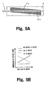
- Fig. 5A illustrates an example configuration according to a fifth embodiment of the present invention.
- an optical fiber 1 with a grating, a substrate 4, a first resistance varying heater 9a, and a second resistance varying heater 9b.
- Fig. 5B is a chart showing a relationship between the temperature of the optical fiber and the position of the heater when the resistance varying heaters 9a and 9b shown in Fig. 5A are generate heat.
- the resistance varying heaters 9a and 9b which, though longer, are the same shape as the grating and are positioned in parallel with the mounting position of the grating of the optical fiber 1, are formed at positions in which variational directions of cross-sectional areas of the heaters in the axial direction of the optical fiber oppose each other in a reverse direction.
- the mounting position of the optical fiber 1 is between the two heaters, and the grating unit of the optical fiber 1 is mounted at a position in parallel with and within ranges of the resistance varying heaters 9a and 9b.
- Heat generating conditions at respective locations of the resistance varying heaters 9a and 9b are mutually opposite, and therefore the optical fiber 1 can have the positive or negative temperature gradient as shown in Fig. 5B. It should be noted that, heat transferring mode to the optical fiber 1 by the resistance varying heaters 9a and 9b, the controlling method for the dispersion characteristic, the mounting method for the optical fiber 1, and the like are the same with those for the fourth embodiment.
- the optical fiber can have a reversible temperature gradient by switching the two heaters, thus the variable width for the initial dispersion quantity can be compensated for in both positive or negative direction, such that the variable dispersion quantity can be doubled for the configuration shown in the fourth embodiment.
- Fig. 6 illustrates a sixth embodiment of the present invention, and in Fig. 6, there are an optical fiber 1 with a grating, a substrate 4, and a sloped heater 10.
- the single sloped heater 10 which is longer than the grating is formed at a predetermined sloped position from the mounting axis of the optical fiber 1, and the grating unit of the optical fiber 1 is mounted on the above-described axis so as to be within the range of the heater 10 . Because the distance between the heater 10 and the optical fiber 1 differs from location to location, the temperature transferred to the optical fiber 1 also differs from location to location. As a result, a temperature gradient can be given to the optical fiber by a single heater. In addition, when the configuration shown for the first to the third embodiments is used as the mounting method for the optical fiber 1, the mounting position of the optical fiber 1 can be stabilized.
- the dispersion characteristic is controlled by giving a predetermined temperature gradient to the optical fiber by varying the heat generating quantity to be given to the heater 10.
- the temperature gradient for the optical fiber can be given by a single heater, a heater control circuit can be simplified by optimization of the shape of the heater, thus reduction in manufacturing cost may be remarkably anticipated.
- Fig. 7A illustrates a seventh embodiment of the present invention
- Fig. 7A there are an optical fiber 1 with a grating, a substrate 4, a first sloped heater 10a, and a second sloped heater 10b.
- Fig. 7B is a chart showing relationship between the temperature of the optical fiber and the position of the heaters when the sloped heaters 10a and 10b shown in Fig. 7A are respectively rendered to generate heat.
- the sloped heaters 10a and 10b have the same shape as the grating, a longer size, and are formed at predetermined sloped positions from the mounting axis of the optical fiber 1 such that central axes of the heaters are parallel with each other and have the mounting axis of the optical fiber 1 in between.
- the sloped heaters 10a and 10b are positioned mutually opposed, and the grating unit of the optical fiber 1 is mounted on the above-described axis so as to be within the range of the sloped heaters 10a and 10b. Because the sloped heaters 10a and 10b are in a reverse relation in distance at respective locations from the optical fiber 1, the optical fiber 1 can have a positive or negative temperature gradient as shown in Fig. 7B. It should be noted that the heat transfer mode to the optical fiber 1 by the sloped heaters 10a and 10b, the controlling method for the dispersion characteristic, and the mounting method of the optical fiber 1 are the same as those for the sixth embodiment.
- variable width can be compensated for both positive or negative direction for the initial dispersion quantity, and the variable dispersion quantity can be doubled for the configuration shown in the sixth embodiment.
- Fig. 8 illustrates an example configuration according to an eighth embodiment of the present invention.
- heaters 3 arranged in a row are formed in a range longer than the grating. With this configuration, the distance between the optical fiber 1 and the heaters 3 is minimized, such that the heat is transferred to the optical fiber from the entire periphery and the internal temperature of the optical fiber 1 can be stabilized. It should be noted that the controlling method for the dispersion characteristic is the same as that in the first embodiment.
- the optical fiber and the heaters are in a closely contacted state, and the heat is transferred to the optical fiber from the entire periphery thereof, such that stable high heat conductive efficiency can be obtained, so that reduction in power consumption and improvement in responsive speed at the time of temperature control can be obtained.
- Fig. 9 illustrates an example configuration according to a ninth embodiment of the present invention.
- an optical fiber 1 with a grating, heaters 3, a plane 11, a core 12, and cladding 13.
- the plane 11 is formed on the cladding 13 of the optical fiber 1, and the heaters 3 arranged in a row for a range longer than the grating are formed on the plane 11. With this configuration, the distance between the core 12 and the heaters 3 of the optical fiber 1 can be minimized. It should be noted that the controlling method for the dispersion characteristic is the same as that described above for the first embodiment.
- the heat resistance of the cladding layer is reduced and remarkable reduction in heater power consumption and remarkable improvement in responsive speed at the time of temperature control can both be obtained.
- Fig. 10 illustrates an example configuration according to a tenth embodiment of the present invention, and in Fig. 10, there are an optical fiber 1 with a grating, a substrate 4, and tapered heaters 14.
- the tapered heaters 14 are formed arranged in a row longer than the grating, and the optical fiber 1 is mounted on such a position that the grating unit is within the range of the heaters 14. Because the temperature near the tapered units of the heaters 14 is highest, heat generated by the tapered units can be transferred to lower temperature regions at gaps by arranging the tapered units at positions neighboring gaps between the heaters . In this way, lower temperatures at gaps between the heaters can be eliminated.
- the mounting position of the optical fiber 1 can be stabilized.
- the dispersion characteristic is controlled by giving the temperature gradient to the optical fiber 1 by differentiating the amount of heat generated by respective heaters 14.
- the temperature of the lower temperature regions in the gaps between the heaters can be raised, variations of the temperature gradient of the optical fiber can be reduced, the heat transfer condition is stabilized, and dispersion compensation accuracy is improved.
- Fig. 11 illustrates an example configuration according to an eleventh embodiment of the present invention.
- an optical fiber 1 with a grating, a substrate 4, heat generators 15, and tapered patterns 16.
- the heaters composed of the heat generators 15 and the tapered patterns 16 are formed arranged in a row for a range longer than the grating, and the optical fiber 1 is mounted at a position such that the grating unit is within the range of the above-described heaters.
- the dispersion characteristic is controlled by giving the temperature gradient to the optical fiber 1 by differentiating respective heat generating quantities of the heat generators 15.
- Fig. 12 illustrates an example configuration according to a twelfth embodiment of the present invention, and in Fig. 12 are shown an optical fiber 1 with a grating, heaters 3, a substrate 4, a grooved cover 6, and metal-contained adhesive agents 17.
- the twelfth embodiment differs from the second embodiment in that the metal-contained adhesive agents are filled in areas such as the gaps between the optical fiber 1 and the heaters 3.
- the configuration and operation are the same as described above for the second embodiment. Because the metal-contained adhesive agents 17 are added with metal particles and generally have higher heat conductivity than an adhesive agent not including any metal, the heat conductivity from the heaters 3 to the optical fiber 1 may be improved.
- this embodiment may also be implemented with the configurations of any of the other embodiments of the present invention.
- Fig. 13 illustrates a thirteenth embodiment of the present invention, and in Fig. 13, there are an optical fiber 1 with a grating, heaters 3, a substrate 4, variable resistors 18, and an electrical circuit 19 for heat generation by the heaters.
- a difference of the thirteenth embodiment from the eleventh embodiment is that, in the thirteenth embodiment, a current or voltage individually supplied to the heaters 3 arranged in a row can be varied by adjusting the variable resistors 18 connected in series with the heaters 3. With this configuration, variations in resistance values of individual heaters can be corrected, and a problem of common use of supply power source can be complied with.
- This embodiment may also be implemented with the configurations shown in other embodiments.
- the optical fiber and the heaters can be closely arranged, stable high heat conductive efficiency can be obtained, such that power consumption can be reduced and response speed can be improved.
- the control circuit for the heater can be simplified by optimization of the shape of the heater.
- variable width can be compensated to both positive or negative direction for the initial dispersion quantity, and the variable dispersion quantity can be doubled for the configuration shown in the fourth embodiment.
- the control circuit for the heater can be simplified by optimization of the shape of the heater.
- variable width can be compensated in both positive or negative direction for the initial dispersion quantity. In this manner, the variable dispersion quantity can be doubled for the configuration shown in the sixth embodiment.
- the optical fiber and the heaters are in closely contact and the heat is transferred to the optical fiber from all peripheral directions, stable high heat conductive efficiency can be obtained, such that power consumption can be reduced, and the responsive speed at the time of the temperature control may be remarkably improved.
- the cladding layer of the optical fiber is made thinner, the heat resistance of the cladding layer is reduced compared with other inventions, such that remarkable reduction in power consumption and remarkable improvement in the responsive speed at the time of the temperature control can both be obtained.
- the temperature at the low temperature regions at gaps between the heaters can be raised, variations in the temperature gradient of the optical fiber can be reduced, and the heat conductive condition is stabilized.
Landscapes
- Physics & Mathematics (AREA)
- General Physics & Mathematics (AREA)
- Optics & Photonics (AREA)
- Chemical & Material Sciences (AREA)
- Dispersion Chemistry (AREA)
- Nonlinear Science (AREA)
- Electromagnetism (AREA)
- Engineering & Computer Science (AREA)
- Computer Networks & Wireless Communication (AREA)
- Signal Processing (AREA)
- Optical Fibers, Optical Fiber Cores, And Optical Fiber Bundles (AREA)
- Optical Modulation, Optical Deflection, Nonlinear Optics, Optical Demodulation, Optical Logic Elements (AREA)
- Optical Couplings Of Light Guides (AREA)
- Mechanical Coupling Of Light Guides (AREA)
Abstract
Description
Claims (13)
- A light dispersion equalizer comprising:wherein said plurality of heaters are arranged on said substrate along said groove.an optical fiber having a grating which causes reflection of light of a predetermined wavelength from signal light propagating through the optical fiber;a substrate having formed thereon a groove for mounting said optical fiber; anda plurality of heaters for regulating the temperature of said optical fiber;
- A light dispersion equalizer comprising:wherein said optical fiber is grasped by said holder and said substrate.an optical fiber having a grating which causes reflection of light of a predetermined wavelength from signal light propagated through the optical fiber;a holder having formed thereon a groove for holding said optical fiber;a plurality of heaters for regulating the temperature of said optical fiber; anda substrate having said plurality of heaters arranged along said groove thereon;
- A light dispersion equalizer comprising:wherein said substrate has a mark indicating mounting position of said optical fiber, and said optical fiber is positioned by said mark and mounted on said heaters.an optical fiber having a grating which causes reflection of light of a predetermined wavelength from signal light propagated through the optical fiber;a plurality of heaters for regulating the temperature of said optical fiber; anda substrate having said plurality of heaters theron;
- A light dispersion equalizer comprising:wherein said heater changes cross-sectional areas thereof in an axial direction of said optical fiber.an optical fiber having a grating which causes reflection of light of a predetermined wavelength from signal light propagated through the optical fiber;a heater for regulating the temperature of said optical fiber; anda substrate having said heater thereon;
- A light dispersion equalizer according to claim 4,
wherein an even number of said heaters are provided; and
the heaters are configured to mutually oppose each other at positions with the same interval from said optical fiber having said optical fiber in their between, and cross-sectional areas of two groups of the heaters, each of the groups comprising one half of the heaters, are in a mutually opposite relationship the axial direction of said optical fiber. - A light dispersion equalizer comprising:wherein said heater is obliquely arranged on said substrate relative to the axis of said optical fiber.an optical fiber having a grating which causes reflection of light of a predetermined wavelength from signal light propagated through the optical fiber;a heater for regulating the temperature of said optical fiber; anda substrate having said heater thereon;
- A light dispersion equalizer according to claim 6;
wherein said heater is in even number, and
two groups of heaters each composed of one half of the heaters in the even number are arranged mutually in parallel having said optical fiber in between. - A light dispersion equalizer comprising:wherein said heaters are arranged on the external periphery of said optical fiber.an optical fiber having a grating which causes reflection of light of a predetermined wavelength from signal light propagated through the optical fiber; andheaters for regulating the temperature of said optical fiber;
- A light dispersion equalizer comprising:wherein said heaters are arranged on a plane formed on external periphery of cladding of said optical fiber.an optical fiber having a grating which causes reflection of light of a predetermined wavelength from signal light propagated through the optical fiber; anda plurality of heaters for regulating the temperature of said optical fiber;
- A light dispersion equalizer comprising:wherein said heaters have tapered units formed at ends thereof.an optical fiber having a grating which causes reflection of light of a predetermined wavelength from signal light propagated through the optical fiber;a plurality of heaters for regulating the temperature of said optical fiber; anda substrate having said heaters thereon;
- A light dispersion equalizer comprising:wherein said heaters have heat generators and tapered patterns connected with said heat generators, and said optical fiber is arranged on said heat generators.an optical fiber having a grating which causes reflection of light of a predetermined wavelength from signal light propagated through the optical fiber;a plurality of heaters for regulating the temperature of said optical fiber; anda substrate having said heater thereon;
- A light dispersion equalizer comprising:an optical fiber having a grating which causes reflection of light of a predetermined wavelength from signal light propagated through the optical fiber;heaters for regulating the temperature of said optical fiber; andmetal-contained resins filled in gaps between said optical fiber and said heaters.
- A light dispersion equalizer comprising:an optical fiber having a grating which causes reflection of light of a predetermined wavelength from signal light propagated through the optical fiber;a plurality of heaters for regulating the temperature of said optical fiber; andvariable resistors respectively connected in series with said plurality of heaters.
Applications Claiming Priority (2)
| Application Number | Priority Date | Filing Date | Title |
|---|---|---|---|
| JP2000321015 | 2000-10-20 | ||
| JP2000321015 | 2000-10-20 |
Publications (2)
| Publication Number | Publication Date |
|---|---|
| EP1199583A2 true EP1199583A2 (en) | 2002-04-24 |
| EP1199583A3 EP1199583A3 (en) | 2004-08-18 |
Family
ID=18799211
Family Applications (1)
| Application Number | Title | Priority Date | Filing Date |
|---|---|---|---|
| EP01117343A Withdrawn EP1199583A3 (en) | 2000-10-20 | 2001-07-18 | Optical fiber dispersion equalizer |
Country Status (5)
| Country | Link |
|---|---|
| US (1) | US20020048430A1 (en) |
| EP (1) | EP1199583A3 (en) |
| KR (1) | KR20020032296A (en) |
| CN (1) | CN1350186A (en) |
| CA (1) | CA2354416A1 (en) |
Cited By (3)
| Publication number | Priority date | Publication date | Assignee | Title |
|---|---|---|---|---|
| EP1363113A3 (en) * | 2002-05-13 | 2004-09-29 | Bartec GmbH | Temperature measurement device using an optical fiber |
| US6980708B2 (en) | 2002-05-13 | 2005-12-27 | Bartec Gmbh | Device for fibre optic temperature measurement with an optical fibre |
| EP1806607A1 (en) * | 2006-01-05 | 2007-07-11 | Danmarks Tekniske Universitet | Package and assembly for optical components such as optical fibres |
Families Citing this family (14)
| Publication number | Priority date | Publication date | Assignee | Title |
|---|---|---|---|---|
| US6757461B2 (en) | 2001-06-11 | 2004-06-29 | Mitsubishi Denki Kabushiki Kaisha | Tunable dispersion compensation device, optical receiver, and optical fiber communication system |
| US6941044B2 (en) | 2001-07-25 | 2005-09-06 | Teraxion Inc. | Tunable optical structure for the compensation of chromatic dispersion in a light signal |
| JP3667689B2 (en) * | 2001-12-10 | 2005-07-06 | 三菱電機株式会社 | Optical fiber holding device, optical dispersion equalizer, and manufacturing method of optical fiber holding device |
| JP2003195234A (en) * | 2001-12-27 | 2003-07-09 | Mitsubishi Electric Corp | Variable dispersion compensator and substrate for variable dispersion compensator |
| JP2003195188A (en) * | 2001-12-27 | 2003-07-09 | Mitsubishi Electric Corp | Variable dispersion compensator and substrate for variable dispersion compensator |
| CA2369953A1 (en) * | 2002-01-28 | 2003-07-28 | Jds Uniphase Inc. | Thermally tunable fiber bragg grating dispersion compensator |
| CA2395905A1 (en) * | 2002-07-26 | 2004-01-26 | Teraxion Inc. | Multi-grating tunable chromatic dispersion compensator |
| US7711224B1 (en) | 2007-09-14 | 2010-05-04 | Teraxion Inc. | Colorless multichannel tunable dispersion compensator |
| US8331745B2 (en) * | 2009-03-18 | 2012-12-11 | Teraxion Inc. | Assembly for applying a temperature gradient to a refractive index grating and chromatic dispersion compensator |
| MY186196A (en) * | 2015-03-19 | 2021-06-30 | Mitsubishi Gas Chemical Co | Entry sheet for drilling and method for drilling processing using same |
| WO2021038597A1 (en) * | 2019-08-29 | 2021-03-04 | Council Of Scientific & Industrial Research | A device and method for positioning micro hot probe for heating hot zone between micro hot probe and chirped brag grating optical fiber |
| CN111157490B (en) * | 2020-01-08 | 2022-09-30 | 暨南大学 | Micro-nano optical fiber long-period grating refractive index sensor |
| CN111766658A (en) * | 2020-06-01 | 2020-10-13 | 杭州奥创光子技术有限公司 | Tuning device of chirped fiber grating and manufacturing method thereof |
| CN116125588B (en) * | 2023-01-13 | 2026-03-24 | 杭州奥创光子技术有限公司 | A fiber optic grating temperature control device |
Family Cites Families (9)
| Publication number | Priority date | Publication date | Assignee | Title |
|---|---|---|---|---|
| JPH08125414A (en) * | 1994-10-25 | 1996-05-17 | Fujitsu Ltd | Delay equalizer |
| US5519796A (en) * | 1995-03-06 | 1996-05-21 | International Business Machines Corporation | Gain equalization using monolithic planar waveguide grating multiplexer and demultiplexer |
| US5671307A (en) * | 1995-04-10 | 1997-09-23 | Universite Laval | Use of a temperature gradient to impose a chirp on a fibre bragg grating |
| JP3052886B2 (en) * | 1997-04-25 | 2000-06-19 | 日本電気株式会社 | Optical submarine gain equalizer, optical submarine transmission line, and laying method thereof |
| US5987200A (en) * | 1997-10-27 | 1999-11-16 | Lucent Technologies Inc. | Device for tuning wavelength response of an optical fiber grating |
| JP3657772B2 (en) * | 1998-04-23 | 2005-06-08 | 沖電気工業株式会社 | Gain flattener |
| JP2000196538A (en) * | 1998-12-25 | 2000-07-14 | Nec Corp | Optical system unit integrating transmission and reception |
| JP2000235170A (en) * | 1999-02-17 | 2000-08-29 | Nec Corp | Variable dispersion compensator |
| US6411746B1 (en) * | 2000-01-18 | 2002-06-25 | Corning Incorporated | Thermally tunable optical devices |
-
2001
- 2001-07-16 US US09/904,508 patent/US20020048430A1/en not_active Abandoned
- 2001-07-18 EP EP01117343A patent/EP1199583A3/en not_active Withdrawn
- 2001-07-26 CA CA002354416A patent/CA2354416A1/en not_active Abandoned
- 2001-09-06 KR KR1020010054660A patent/KR20020032296A/en not_active Ceased
- 2001-09-07 CN CN01132595A patent/CN1350186A/en active Pending
Cited By (5)
| Publication number | Priority date | Publication date | Assignee | Title |
|---|---|---|---|---|
| EP1363113A3 (en) * | 2002-05-13 | 2004-09-29 | Bartec GmbH | Temperature measurement device using an optical fiber |
| US6980708B2 (en) | 2002-05-13 | 2005-12-27 | Bartec Gmbh | Device for fibre optic temperature measurement with an optical fibre |
| EP1806607A1 (en) * | 2006-01-05 | 2007-07-11 | Danmarks Tekniske Universitet | Package and assembly for optical components such as optical fibres |
| WO2007076872A1 (en) * | 2006-01-05 | 2007-07-12 | Danmarks Tekniske Universitet | Package and assembly for optical components such as optical fibres |
| US7988369B2 (en) | 2006-01-05 | 2011-08-02 | Danmarks Tekniske Universitet | Package and assembly for optical components such as optical fibres |
Also Published As
| Publication number | Publication date |
|---|---|
| EP1199583A3 (en) | 2004-08-18 |
| KR20020032296A (en) | 2002-05-03 |
| US20020048430A1 (en) | 2002-04-25 |
| CN1350186A (en) | 2002-05-22 |
| CA2354416A1 (en) | 2002-04-20 |
Similar Documents
| Publication | Publication Date | Title |
|---|---|---|
| EP1199583A2 (en) | Optical fiber dispersion equalizer | |
| US6937793B2 (en) | Tunable chromatic dispersion compensator | |
| US9705278B2 (en) | Resolution of mode hopping in the output of laser cavities | |
| EP1065534A1 (en) | Phase adjuster using slotted, concatenated waveguides and thermo-optic or electro-optic inserts | |
| CN100419477C (en) | Optical waveguide device, variable optical attenuator and its array, optical switch and its array | |
| US6810179B2 (en) | Variable dispersion compensator | |
| WO2007103880A2 (en) | Dynamically tunable waveguide chip for optical transforms | |
| US20030123800A1 (en) | Variable dispersion compensator and substrate for the same | |
| JP5359412B2 (en) | Variable dispersion compensator | |
| US6941044B2 (en) | Tunable optical structure for the compensation of chromatic dispersion in a light signal | |
| KR100416993B1 (en) | Optical element integrated heat transferring device for plc | |
| JP2002196290A (en) | Optical dispersion equalizer | |
| JP5051037B2 (en) | Variable dispersion compensator | |
| US6898002B2 (en) | Optical device, optical module, optical amplifier, and optical transmission system | |
| JP2005156584A (en) | Dispersion compensation module | |
| WO2003010586A2 (en) | Optical structure for the compensation of chromatic dispersion | |
| JP2011065026A (en) | Fiber bragg grating device | |
| JP2003195188A (en) | Variable dispersion compensator and substrate for variable dispersion compensator | |
| JP2005266409A (en) | Dispersion compensator | |
| JP4772390B2 (en) | Variable dispersion compensator | |
| JP2003307636A (en) | Optical device | |
| JP2004334052A (en) | Variable dispersion compensation module | |
| CN100335943C (en) | Multi-channel integrated tunable thermo-optic lens and dispersion compensator | |
| JPS60192913A (en) | Waveguide type light reflector | |
| CA2454687A1 (en) | Optical structure for the compensation of chromatic dispersion |
Legal Events
| Date | Code | Title | Description |
|---|---|---|---|
| PUAI | Public reference made under article 153(3) epc to a published international application that has entered the european phase |
Free format text: ORIGINAL CODE: 0009012 |
|
| AK | Designated contracting states |
Kind code of ref document: A2 Designated state(s): AT BE CH CY DE DK ES FI FR GB GR IE IT LI LU MC NL PT SE TR |
|
| AX | Request for extension of the european patent |
Free format text: AL;LT;LV;MK;RO;SI |
|
| RIC1 | Information provided on ipc code assigned before grant |
Ipc: 7G 02B 6/16 B Ipc: 7G 02B 6/34 A |
|
| PUAL | Search report despatched |
Free format text: ORIGINAL CODE: 0009013 |
|
| AK | Designated contracting states |
Kind code of ref document: A3 Designated state(s): AT BE CH CY DE DK ES FI FR GB GR IE IT LI LU MC NL PT SE TR |
|
| AX | Request for extension of the european patent |
Extension state: AL LT LV MK RO SI |
|
| AKX | Designation fees paid | ||
| REG | Reference to a national code |
Ref country code: DE Ref legal event code: 8566 |
|
| STAA | Information on the status of an ep patent application or granted ep patent |
Free format text: STATUS: THE APPLICATION IS DEEMED TO BE WITHDRAWN |
|
| 18D | Application deemed to be withdrawn |
Effective date: 20050201 |