EP1199580A2 - A method and apparatus for precursor based radar - Google Patents
A method and apparatus for precursor based radar Download PDFInfo
- Publication number
- EP1199580A2 EP1199580A2 EP01124323A EP01124323A EP1199580A2 EP 1199580 A2 EP1199580 A2 EP 1199580A2 EP 01124323 A EP01124323 A EP 01124323A EP 01124323 A EP01124323 A EP 01124323A EP 1199580 A2 EP1199580 A2 EP 1199580A2
- Authority
- EP
- European Patent Office
- Prior art keywords
- precursor
- electromagnetic wave
- spectra
- pulse
- generate
- Prior art date
- Legal status (The legal status is an assumption and is not a legal conclusion. Google has not performed a legal analysis and makes no representation as to the accuracy of the status listed.)
- Granted
Links
Images





Classifications
-
- G—PHYSICS
- G01—MEASURING; TESTING
- G01S—RADIO DIRECTION-FINDING; RADIO NAVIGATION; DETERMINING DISTANCE OR VELOCITY BY USE OF RADIO WAVES; LOCATING OR PRESENCE-DETECTING BY USE OF THE REFLECTION OR RERADIATION OF RADIO WAVES; ANALOGOUS ARRANGEMENTS USING OTHER WAVES
- G01S7/00—Details of systems according to groups G01S13/00, G01S15/00, G01S17/00
- G01S7/02—Details of systems according to groups G01S13/00, G01S15/00, G01S17/00 of systems according to group G01S13/00
- G01S7/03—Details of HF subsystems specially adapted therefor, e.g. common to transmitter and receiver
-
- G—PHYSICS
- G01—MEASURING; TESTING
- G01S—RADIO DIRECTION-FINDING; RADIO NAVIGATION; DETERMINING DISTANCE OR VELOCITY BY USE OF RADIO WAVES; LOCATING OR PRESENCE-DETECTING BY USE OF THE REFLECTION OR RERADIATION OF RADIO WAVES; ANALOGOUS ARRANGEMENTS USING OTHER WAVES
- G01S7/00—Details of systems according to groups G01S13/00, G01S15/00, G01S17/00
- G01S7/02—Details of systems according to groups G01S13/00, G01S15/00, G01S17/00 of systems according to group G01S13/00
- G01S7/28—Details of pulse systems
- G01S7/282—Transmitters
-
- G—PHYSICS
- G01—MEASURING; TESTING
- G01S—RADIO DIRECTION-FINDING; RADIO NAVIGATION; DETERMINING DISTANCE OR VELOCITY BY USE OF RADIO WAVES; LOCATING OR PRESENCE-DETECTING BY USE OF THE REFLECTION OR RERADIATION OF RADIO WAVES; ANALOGOUS ARRANGEMENTS USING OTHER WAVES
- G01S7/00—Details of systems according to groups G01S13/00, G01S15/00, G01S17/00
- G01S7/02—Details of systems according to groups G01S13/00, G01S15/00, G01S17/00 of systems according to group G01S13/00
- G01S7/41—Details of systems according to groups G01S13/00, G01S15/00, G01S17/00 of systems according to group G01S13/00 using analysis of echo signal for target characterisation; Target signature; Target cross-section
-
- G—PHYSICS
- G01—MEASURING; TESTING
- G01S—RADIO DIRECTION-FINDING; RADIO NAVIGATION; DETERMINING DISTANCE OR VELOCITY BY USE OF RADIO WAVES; LOCATING OR PRESENCE-DETECTING BY USE OF THE REFLECTION OR RERADIATION OF RADIO WAVES; ANALOGOUS ARRANGEMENTS USING OTHER WAVES
- G01S7/00—Details of systems according to groups G01S13/00, G01S15/00, G01S17/00
- G01S7/02—Details of systems according to groups G01S13/00, G01S15/00, G01S17/00 of systems according to group G01S13/00
- G01S7/41—Details of systems according to groups G01S13/00, G01S15/00, G01S17/00 of systems according to group G01S13/00 using analysis of echo signal for target characterisation; Target signature; Target cross-section
- G01S7/418—Theoretical aspects
Definitions
- the present invention relates to radar. More particularly, the present invention relates to a method and apparatus for identifying materials based on propagation characteristics of electromagnetic energy other than through air or free space.
- Prior art radar systems are generally responsive to target cross section of the first object encountered and, with certain exceptions such as, for example, imaging radar or interrogating radar, cannot provide additional information regarding the contact.
- Such prior art radar systems further are incapable of generating a useable return from absorptive or dispersive materials, as energy associated with a transmitted radar signal is either absorbed or scattered by such materials to the extent that the energy return is negligible.
- U.S. Patent No. 4,408,156 to Veys describes a method and an apparatus for identifying sheet articles of non-conductive material which are marked for identification purposes.
- the method and apparatus of Veys includes producing an identification signal for a sheet article of non-conductive material by incorporating a small quantity of thin conductive fibers capable absorbing and reflecting microwave radiation energy.
- Veys does not disclose the use of precursors.
- U.S. Patent No. 5,315,561 to Grossi describes a system for transmitting an electromagnetic signal under water.
- the system of Grossi uses a low-frequency signal to overcome the absorptive properties of salt water and receives a scattered reflected signal from anomalies below the surface of the water.
- the system of Grossi in using low-frequency signals gains the advantage of deeper penetration in terms of skin depths as compared to a transmitter using higher frequency signals.
- Grossi fails to make use of precursors.
- signal processing may be performed to identify an object in an environment, including receiving a precursor associated with an electromagnetic wave interacting with the object.
- Various properties associated with the object may be identified using one or more characteristics associated with the received precursor.
- the electromagnetic wave may be transmitted with a characteristic such as, for example, a sharp rise time, so as to generate the precursor when the electromagnetic wave interacts with the object.
- a characteristic may be generated using a circuit which includes the use of capacitive discharge and a semiconductor device such as a Drift Step Recovery Diode.
- an electromagnetic wave having the desired characteristics may be generated using a microwave diode switch where the signal may then be amplified through, for example, a broadband semiconductor amplifier or a traveling wave tube amplifier.
- the characteristic of the electromagnetic wave may include at least one phase reversal which may be achieved by dividing the electromagnetic wave and producing a divided signal and then phase modulating the original electromagnetic wave with the divided signal to generate the phase reversal.
- Phase reversals like sharp rise time pulses, ARE be capable of generating precursors when such an electromagnetic wave having phase reversals interacts with the object.
- one or more channels may be established corresponding to one or more possible characteristics associated with the precursor such as, for example, precursor spectra.
- Each of the one or more channels may be associated with a corresponding one of one or more possible material properties associated with the object.
- the corresponding precursor spectra associated with the possible material properties may include, for example, water generated precursor spectra, radar absorptive material generated precursor spectra, and metallic oxides RUST generated precursor spectra.
- a color display may present an image of the object with the material properties associated with the object indicated by displaying each of the material properties with a corresponding color. Colors associated with the material properties of the object may be displayed in proportion to respective values associated with one or more received precursor spectra.
- electromagnetic wave 110 When electromagnetic wave 110 is applied to media 120 characterized as a dielectric such as is illustrated in FIG 1, individual polarizable atoms or molecules 121 may become excited. Each atom or molecule 121 be regarded as small mass 131 spring 132 damper system 130, with an associated time constant 133. Prior to the arrival of electromagnetic wave 110, for example in region 122, atoms or molecules 121 are subject only to thermal agitation. After electromagnetic wave 110 is established, for example in region 123, energy continuously couples between electromagnetic wave 110 and atom or molecules 121, creating a perturbation or excitation of atoms or molecules 121 in synchronization with the frequency of electromagnetic wave 110.
- the synchronous movement of atoms or molecules 121 creates individual fields which oppose the energy field from electromagnetic wave 110 and create a phase delay which slows electromagnetic wave 110 propagation by the refractive index of the material.
- the interaction between electromagnetic wave 110 in the time period near wave edge 111 and atoms or molecules 121 of media 120 creates the precursor phenomena, which may last on the order of time constant 133 associated with mass-spring damper system 130.
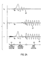
- composite signal 240 is shown containing a main signal (shown individually at 231), the Brillouin precursor (shown individually at 221) and Sommerfeld precursor 210.
- Sommerfeld precursor 210 begins at an infinite frequency and drops to near the resonant frequency associated with media 120.
- the leading edge of the Sommerfeld Precursor 210 travels with relatively little energy at the speed of light in vacuum through the material.
- Brillouin precursor 220 has a complex frequency and resembles a Gaussian-like pulse traveling at the leading edge of main carrier signal 230. It is further known that Brillouin precursor 220 has more energy than Sommerfeld Precursor 210.
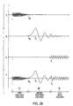
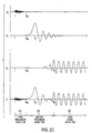
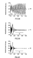
- FIG 2B, 2C, and 2D Graphs illustrating exemplary precursor waveforms associated with reflections from a radar absorptive material are illustrated in FIG 2B, 2C, and 2D. It should be noted that the exact characteristic of the returned precursor may be influenced by, for example, the frequency of the incident electromagnetic wave, the material from which the wave is reflected, and so on, as previously described.
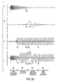
- FIG 2D for example illustrates exemplary precursor waveforms as may be generated, for example, from water.
- graphs 310, 320, and 330 illustrate precursor characteristics associated with, for example, absorptive materials of different "skin depth".
- Standard radar signals may be absorbed exponentially in lossy media, with carrier power dropping at an exponential rate with respect to distance.
- the attenuation generally results from a damping action of the material characterized as mass spring damper system 130 at the molecular level as illustrated in and described with reference to FIG 1. Since precursors do not couple strongly to the molecular resonance that causes losses associated with the principal carrier signal, precursors propagate with far lower loss - on the order of I/SQRT(distance). Thus, a precursor field can penetrate deeply into lossy media such a damp soil, foliage, or radar absorbing material.
- Exemplary radar system 400 may preferably include, for example, transmitter section 400a configured to generate signals capable of generating precursors and receiver section 400b configured to receive the signals and precursors, wherein the sections are embodied jointly in the same platform.
- signals capable of generating precursors may be separately generated by, for example, transmitter section 400a, and precursors may be separately received by receiver section 400b in accordance with the present invention wherein the sections, for example, are embodied in separate platforms. It should be noted that by generating signals capable of generating precursors as hereinafter described, and by processing information associated with received precursor signals, information related to, for example, the material properties of object 420 in a radar field may be provided even if object 420 is obscured by absorptive media.
- a precursor may be generated when there is a change in the amplitude or character of an electromagnetic field, such as for example the field associated with electromagnetic wave 110, interacting with media 120, or like lossy or absorptive media which may be characterized generally as a dielectric.
- an electromagnetic field such as for example the field associated with electromagnetic wave 110
- media 120 or like lossy or absorptive media which may be characterized generally as a dielectric.
- a high power signal with a sharp rise time is needed.
- impulse generator 410 may be used for generating a magnetic pulse capable of generating precursors in objects. It will be appreciated to those skilled in the art that several methods may be used in impulse generator 410 to generate impulse signal 413 having the desired characteristics, e.g. sharp rise time, high power, and the like.
- One such method associated with one exemplary embodiment as illustrated in FIG 4B may include the use of spark gap generator 440.
- capacitor 442 may be charged to a high voltage using voltage source 441, then suddenly discharged across spark gap 444, for example, by closing switch 443, creating an impulse of many kilovolts.
- An electromagnetic signal associated with such a pulse has very broad spectral characteristics, and no clearly defined carrier frequency.
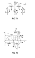
- Spark gap generator 440 may be followed by a semiconductor device, which further sharpens the signal rise time, such as a Drift Step Recovery Diode as will be described in greater detail hereinafter with regard to FIG 7A and FIG 7B.
- microwave diode switch generator 450 may be used to create a sharp rise time pulse.
- a voltage signal from, for example, source 451 may be applied to microwave diode switch 452 and switched by applying a switching control signal thereto at 453.
- the resulting impulse signal may be amplified through amplifier 454 which may preferably be, for example, a broadband semiconductor amplifier or traveling wave tube amplifier.
- Generating an impulse using microwave diode switch generator 450 may be better compatible with existing radar systems, and thus has the advantage that any existing radar functions are easily retained.
- amplifier 454 and related transmission lines associated with the use of microwave diode switch generator 450 and amplifier 454 in the present embodiment or similarly configured embodiments may be important, as, for example, bandwidth and dispersion characteristics may cause their own precursors to be generated.
- the bandwidth of an amplifier is proportional to the rise time of the pulse that it will pass therefore broadband devices are preferable with the possibility of additional requirements for equalization, and the like such as, for example, at equalizer 455.
- another method for generating a suitable signal in impulse generator 410 is to phase modulate a fixed carrier signal.
- a signal such as, for example, a 16 GHz carrier signal may be applied to high-speed counter 462 at input 461, counter 462 configured, for example, to divide by 4.
- the divided output of counter 462 may be used to modulate the original carrier signal with broadband mixer 463.
- the resulting output signal at output 464 may contain a 180-degree phase reversal every 4 cycles sufficient to excite precursor fields. Accordingly, a larger amount of energy may be induced into precursor fields reflected, for example, from object 420.
- DC loading on, for example, power amplifier 411 associated with such an embodiment may remain constant throughout the period where the precursor exciting phase reversals or "pulses" are generated. It will further be appreciated that the present embodiment could easily be switched on and off, or otherwise gated or controlled, allowing greater waveform flexibility.
- conventional broadband antenna system 412 may be used to emit signals capable of generating precursor fields when interacting with objects as previously described.
- Broadband antenna system 412 may further be preferably embodied in, for example, a folded horn antenna as will be described in greater detail hereinafter.
- Precursors generated and returned from, for example, object 420, as well as conventional radar returns may further be received using broadband antenna system 412 or separate antenna system 433 as shown. Precursors and, in some instances normal signal reflections may be reflected from object 420 and received at receive antenna 433.
- processor 430 may be configured to perform signal processing in accordance with the present invention to process precursor signals, and, for example, identify materials associated with object 420. Since one aim of the present invention is to provide information to a user, information related to precursor returns may be displayed on display device 434, which may be, for example, a CRT display, plasma display, heads up display, flat panel display, or the like display as would be known in the art.
- display device 434 may be, for example, a CRT display, plasma display, heads up display, flat panel display, or the like display as would be known in the art.
- Information related to precursors may also be stored in storage device 435, which may be, for example, a disk drive - optical or magnetic, a floppy drive, a primary memory such as a RAM or the like. Moreover, as it will be appreciated, information related to precursors may be communicated to other radar systems through communication link 436.
- the performance of receiver section 400b is of some concern, and thus, the spectral characteristic of the precursor may be used to facilitate processor 430 in handling precursors. It should be noted that while signal frequency has some impact on precursor generation, the spectral characteristic of the precursor is largely independent of the signal that creates it. It should further be noted that materials with different dispersion curves will return distinct precursor spectra. With reference again to FIG 2D, precursor spectra are shown as, for example, signal portions corresponding to the first precursor evolution at 210, and the second precursor evolution at 220.
- processor 430 may be configured with a number of different receiver channels, with one channel configured as a conventional radar channel having, for example, a filter matched to the pulse width of, for example, impulse signal 413. Additional channels, such as, for example, 3 separate channels matched to different precursor spectra for water generated precursors, radar absorptive material generated precursors, and precursors generated by metallic oxides would be preferable. A composite of the signals from these 4 channels would be presented to display 434 where, for example, an operator could view each channel as a separate color, with the conventional radar return providing, for example, a conventional black and white display image. Information from other material channels may be added as different colors, thus indicating which materials are present in a given radar return image.
- a signal from a metallic oxide would be displayed as COLOR 1 and would indicate, for example, a vehicle, oil drum, metallic mine or the like.
- a signal from a water-bearing object for example, would be displayed as COLOR 2 and would indicate, for example, a person, a tree, a pond or the like.
- Signals from Radar absorptive objects may not produce any return on a conventional radar channel, but would provide a signal return on a precursor channel and would be displayed, for example, with COLOR 3. As will be described in greater detail hereinafter, such a system has clear advantages associated with target selection for military operations.
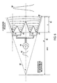
- One exemplary antenna with preferable characteristics however, is folded long horn antenna 500 as illustrated in FIG 5.
- separate synchronized pulse input signals 511, 521, 531, and 541 may be applied respectively at voltage sources 510, 520, 530, and 540 to the base sections of respective horn sections 512, 522, 532, and 542.
- Respective component pulses 513, 523, 533, and 543 may propagate along individual horn sections and converge at sections 514 and 534. Pulses 513 and 523 may converge in section 514 to form additive pulse 502, and pulses 533 and 543 may likewise converge in section 534 to form additive pulse 503.
- Additive pulses 502 and 503 may converge in section 515 to form output pulse 501 with an even greater amplitude representing the sum of pulses 502 and 503.
- FIG 5 shows four pulses being generated and combined, a greater or fewer number of pulses may be generated and combined in a similar manner.
- folded long horn antenna 500 is a shorter folded horn antenna 600.
- apex angle 640 is set for the same aperture as that of folded long horn antenna 500.
- folded horn antenna 600 may generate a suitable pulse 601 for generating precursors by applying a smaller pulse 615 at voltage source 610 to the respective bases 611-614 of folded horn antenna 600. Resulting individual pulses may converge in the common horn section and sum to form pulse 601.
- generating pulses such as, for example, pulse 615, or pulses 511, 521, 531, or 541 may be generated in one of several ways. While spark gap devices may be used, as described, the life cycle of a spark gap device is limited due to the destructive action of the spark generated by the device on its anode and cathode. Thus, a preferred manner of generating such pulses is by the operation of ultra fast microwave switches. Some fast semiconductor switches may be operated in the order of a few nanoseconds at, for example, 1jV and hundreds of amperes switching current. However, if higher voltages are desired the corresponding need to increase the size of the semiconductor material leads to higher turn-on times.
- Transition from one state to another can occur at less than 1 nanosecond and may be induced by delayed ionization by the application of a short, high voltage pulse to the blocking p-n junction of a many-layered n+pnp+ structure.
- Regenerative feedback may keep the device turned on indefinitely necessitating the intervention by an external circuit to switch off the device.
- DSRD Drift Step Recovery Diodes
- Symmetrical circuit 700 may operate as follows. Capacitors C1 704 and C2 703 may be initially charged and switches S1 706 and S2 705 are initially open. It should be noted that capacitors C1 704 and C2 703 may be charged to opposite polarities. Switch S1 706 may be closed discharging capacitor C1 704 through inductor L1 708 and DSRD 710. Discharge current I1 711 is a forward current for DSRD 710 and thus resistance in DSRD 710 is low causing current I1 711 to oscillate.
- the voltage associated with output pulse 720 may be greater than an order of magnitude greater than initial capacitor voltage.
- the high voltage is only present in the circuit for a short time thereby minimizing the disadvantages of generating finite DC voltage at such high levels which disadvantages include, for example, corona and are discharge.
- FIG 8A, FIG 8B, and FIG 8C illustrate several exemplary receiver characteristics which may be useful in configuring, for example, a receiver transfer characteristic that is capable of receiving precursor signals.
- FIG 8A shows a time domain transfer characteristic 810 including exemplary theoretical matched filter response curve 811 for an exemplary receiver configured to receive precursors. It can be seen that in accordance with various exemplary embodiments of the present invention, matching filter characteristics allows for maximum pass characteristics, e.g. allows for the passage of the maximum amount of energy from the desired waveform while suppressing the maximum amount of noise.
- FIG 8B shows transfer characteristic 820 including an non-theoretical matched filter response curve 821 for an exemplary receiver configured to receive a conventional square wave pulses with a frequency centered at f t 822.
- FIG 8C shows transfer characteristic 800 including matched filter response curve 831 for an exemplary receiver configured to receive square wave signals centered at f t 832.
- FIG 9A illustrates exemplary military operational scenario 900 wherein airborne radar platform 910 may provide, for example, the capability to transmit signals 911 capable of generating precursors.
- signals 911 are transmitted into a target environment containing radar absorptive material such as, for example, foliage 930.
- Scatter 913 may be generated from foliage 930, however, precursors may be generated which penetrate foliage 930 and coim into contact with, for example, object 920 which may be a tank or other military assest using foliage 930 as cover.
- Precursor 913 return may be detected in the receiver section of airborne radar platform 910 and processed accordingly.
- FIG 9B and FIG 9C Additional civilian applications may exist in accordance with the present invention as illustrated in FIG 9B and FIG 9C.
- a short-range system having transmitter/receiver 952 could be used to examine the contents of packages 950, and indicate the general type of material 951 they contain by irradiating packages 950 with signal 911 capable, as described with reference to FIG 9A, of generating precursors.
- Customs officials could use this to identify a variety of contraband, including drugs, illegal plant or foodstuffs, and the like.
- precursor radar 942 could provide detailed images of subterranean objects 941. This would be useful for locating pipes & wires, buried structures, and objects of archeological interest.
Landscapes
- Engineering & Computer Science (AREA)
- Computer Networks & Wireless Communication (AREA)
- Physics & Mathematics (AREA)
- General Physics & Mathematics (AREA)
- Radar, Positioning & Navigation (AREA)
- Remote Sensing (AREA)
- Radar Systems Or Details Thereof (AREA)
Abstract
Description
Claims (20)
- A method for signal processing to identify an object in an environment, the method comprising the steps of:receiving a precursor associated with a first electromagnetic wave interacting with the object; andidentifying a property of the object using one or more characteristics associated with the received precursor.
- The method of claim 1, further comprising the step of
transmitting the first electromagnetic wave with a characteristic so as to generate the precursor when the first electromagnetic wave interacts with the object. - The method of claim 2, wherein the characteristic of the first electromagnetic wave includes a pulse having a sharp rise time, and wherein the step of transmitting further comprises the steps of:generating the pulse using a circuit including capacitive discharge; andgenerating the sharp rise time using the circuit including a semiconductor device.
- The method of claim 3, wherein the semiconductor device includes a Drift Step Recovery Diode.
- The method of claim 2, wherein the characteristic of the first electromagnetic wave includes a pulse having a sharp rise time, and wherein the step of transmitting further comprises the steps of:generating the first electromagnetic wave using a microwave diode switch;
andamplifying the first electromagnetic wave through a broadband semiconductor amplifier. - The method of claim 2, wherein the characteristic of the first electromagnetic wave includes a pulse having a sharp rise time, and wherein the step of transmitting further comprises the steps of:generating the first electromagnetic wave using a microwave diode switch;
andamplifying the first electromagnetic wave through a traveling wave tube amplifier. - The method of claim 2, wherein the characteristic of the first electromagnetic wave includes at least one phase reversal, and wherein the step of transmitting further comprises the step of phase modulating the first electromagnetic wave to generate the at least one phase reversal so as to generate the precursor when the phase modulated first electromagnetic wave interacts with the object.
- The method of claim 1, wherein the step of receiving further comprises the steps of:establishing one or more channels corresponding to the one or more possible characteristics associated with the precursor; andassociating each of the one or more channels with a corresponding one of one or more possible material properties associated with the object.
- The method of claim 8, wherein the each of one or more possible characteristics includes a corresponding precursor spectra associated with the corresponding one or the one or more possible material properties and wherein the corresponding precursor spectra include one of: water generated precursor spectra, radar absorptive material generated precursor spectra, and metallic oxides generated precursor spectra.
- The method of claim 9, further comprising the steps of:presenting a color display including an image of the object; andindicating which of the one or more possible material properties are associated with the object by displaying each of the one or more material properties with a corresponding color in proportion to one or more respective values associated with one or more received precursor spectra.
- An apparatus for signal processing to identify an object in an environment, the apparatus comprising:a receive antenna; anda receiver coupled to the antenna, the receiver configured to:receive a precursor associated with a first electromagnetic wave interacting with the object; andidentify a property of the object using one or more characteristics associated with the received precursor.
- The apparatus of claim 11, further comprising:a transmit antenna; anda transmitter coupled to the transmit antenna, the transmitter configured to:transmit the first electromagnetic wave with a characteristic so as to generate the precursor when the first electromagnetic wave interacts with the object.
- The apparatus of claim 12, wherein the characteristic of the first electromagnetic wave includes a pulse having a sharp rise time, and wherein the transmitter is further configured to:generate the pulse using a circuit including capacitive discharge; andgenerate the sharp rise time using the circuit including a semiconductor device.
- The apparatus of claim 13, wherein the semiconductor device includes a Drift Step Recovery Diode.
- The apparatus of claim 12, wherein the characteristic of the first electromagnetic wave includes a pulse having a sharp rise time, and wherein the transmitter is further configured to:generate the first electromagnetic wave using a microwave diode switch; andamplify the first electromagnetic wave through a broadband semiconductor amplifier.
- The apparatus of claim 12, wherein the characteristic of the first electromagnetic wave includes a pulse having a sharp rise time, and wherein the transmitter is further configured to:generate the first electromagnetic wave using a microwave diode switch; andamplify the first electromagnetic wave through a traveling wave tube amplifier.
- The apparatus of claim 12, wherein the characteristic of the first electromagnetic wave includes at least one phase reversal, and wherein the transmitter is further configured to phase modulate the first electromagnetic wave to generate the at least one phase reversal so as to generate the precursor when the first electromagnetic wave interacts with the object.
- The apparatus of claim 11, wherein the receiver is further configured to:establish one or more channels corresponding to the one or more possible characteristics associated with the precursor; andassociate each of the one or more channels with a corresponding one of one or more possible material properties associated with the object.
- The apparatus of claim 18, wherein the each of one or more possible characteristics includes a corresponding precursor spectra associated with the corresponding one or the one or more possible material properties and wherein the corresponding precursor spectra include one of: water generated precursor spectra, radar absorptive material generated precursor spectra, and metallic oxides generated precursor spectra.
- The apparatus of claim 19, further comprising:a display coupled to the receiver, the receiver further configured to:present a color display including an image of the object on the display; andindicate which of the one or more possible material properties are associated with the object by displaying each of the one or more material properties with a corresponding color in proportion to one or more respective values associated with one or more received precursor spectra.
Applications Claiming Priority (2)
| Application Number | Priority Date | Filing Date | Title |
|---|---|---|---|
| US691177 | 2000-10-19 | ||
| US09/691,177 US6429801B1 (en) | 2000-10-19 | 2000-10-19 | Method and apparatus for precursor based radar |
Publications (3)
| Publication Number | Publication Date |
|---|---|
| EP1199580A2 true EP1199580A2 (en) | 2002-04-24 |
| EP1199580A3 EP1199580A3 (en) | 2002-05-15 |
| EP1199580B1 EP1199580B1 (en) | 2004-09-22 |
Family
ID=24775460
Family Applications (1)
| Application Number | Title | Priority Date | Filing Date |
|---|---|---|---|
| EP01124323A Expired - Lifetime EP1199580B1 (en) | 2000-10-19 | 2001-10-19 | A method and apparatus for precursor based radar |
Country Status (5)
| Country | Link |
|---|---|
| US (1) | US6429801B1 (en) |
| EP (1) | EP1199580B1 (en) |
| CA (1) | CA2359376A1 (en) |
| DE (1) | DE60105730T2 (en) |
| TR (1) | TR200402473T4 (en) |
Families Citing this family (5)
| Publication number | Priority date | Publication date | Assignee | Title |
|---|---|---|---|---|
| US7437305B1 (en) | 1999-05-11 | 2008-10-14 | Christopher Angel Kantarjiev | Scheduling delivery of products via the internet |
| US7240283B1 (en) | 2000-11-10 | 2007-07-03 | Narasimha Rao Paila | Data transmission and rendering techniques implemented over a client-server system |
| US7447114B2 (en) | 2005-08-31 | 2008-11-04 | Geotrace Technologies, Inc. | Non-linear seismic trace matching to well logs |
| US8570207B1 (en) * | 2010-06-09 | 2013-10-29 | Arrowhead Center, Inc. | Method, technique, and system for detecting Brillouin precursors at microwave frequencies for enhanced performance in various applications |
| EP4187280B1 (en) * | 2021-11-26 | 2024-05-22 | Acconeer AB | A method for performing radar measurements and a radar device |
Family Cites Families (21)
| Publication number | Priority date | Publication date | Assignee | Title |
|---|---|---|---|---|
| US4053891A (en) * | 1967-05-24 | 1977-10-11 | Lockheed Electronics Company | Radar object detector using non-linearities |
| US3798643A (en) * | 1972-06-27 | 1974-03-19 | Us Air Force | Pulsed doppler radar |
| US4408156A (en) | 1979-05-01 | 1983-10-04 | N. V. Bekaert S.A. | Sheet articles of non-conductive material marked for identification purposes, and method and apparatus for identifying such articles |
| US5140332A (en) * | 1989-07-13 | 1992-08-18 | Westinghouse Electric Corp. | Short pulse radar system with a long pulse transmitter |
| US5053772A (en) | 1990-09-04 | 1991-10-01 | Electronics & Space Corporation | Radar system employing a method for motion and range closure compensation |
| US5241314A (en) | 1991-08-16 | 1993-08-31 | Kaman Aerospace Corporation | Image lidar transmitter downlink for command guidance of underwater vehicle |
| US5248976A (en) | 1991-11-27 | 1993-09-28 | Hughes Aircraft Company | Multiple discrete autofocus |
| US5191343A (en) * | 1992-02-10 | 1993-03-02 | United Technologies Corporation | Radar target signature detector |
| US5546084A (en) | 1992-07-17 | 1996-08-13 | Trw Inc. | Synthetic aperture radar clutter reduction system |
| US5262781A (en) | 1992-10-07 | 1993-11-16 | Teledyne Ryan Aernautical, Division Of Teledyne Industries, Inc. | Wideband electromagnetic imaging system |
| US5357253A (en) | 1993-04-02 | 1994-10-18 | Earth Sounding International | System and method for earth probing with deep subsurface penetration using low frequency electromagnetic signals |
| US5315561A (en) | 1993-06-21 | 1994-05-24 | Raytheon Company | Radar system and components therefore for transmitting an electromagnetic signal underwater |
| US5381154A (en) * | 1993-09-03 | 1995-01-10 | Guerci; Joseph R. | Optimum matched illumination-reception radar for target classification |
| US5502444A (en) | 1994-09-23 | 1996-03-26 | Mandex, Inc. | Method and apparatus for improving the signal-to-clutter ratio of an airborne earth penetrating radar |
| US5598152A (en) | 1994-12-29 | 1997-01-28 | The United States Of America As Represented By The Secretary Of The Navy | Mine sweeping system for magnetic and non-magnetic mines |
| AU7328696A (en) * | 1995-11-15 | 1997-06-05 | Vladimir M. Efanov | Pulse generating circuits using drift step recovery devices |
| US5644314A (en) * | 1996-03-29 | 1997-07-01 | The United States Of America As Represented By The Secretary Of The Army | Portable geophysical system using an inverse collocation-type metehodology |
| SE509733C2 (en) * | 1996-07-05 | 1999-03-01 | Foersvarets Forskningsanstalt | Ways of detecting and classifying objects using radar |
| AU2420497A (en) * | 1996-11-22 | 1998-06-10 | Itt Manufacturing Enterprises, Inc. | Integrated precision approach radar display |
| US6026125A (en) * | 1997-05-16 | 2000-02-15 | Multispectral Solutions, Inc. | Waveform adaptive ultra-wideband transmitter |
| US5892479A (en) | 1997-07-30 | 1999-04-06 | The United States Of America As Represented By The Secretary Of The Army | Electromagnetic target generator |
-
2000
- 2000-10-19 US US09/691,177 patent/US6429801B1/en not_active Expired - Fee Related
-
2001
- 2001-10-19 EP EP01124323A patent/EP1199580B1/en not_active Expired - Lifetime
- 2001-10-19 DE DE60105730T patent/DE60105730T2/en not_active Expired - Fee Related
- 2001-10-19 CA CA002359376A patent/CA2359376A1/en not_active Abandoned
- 2001-10-19 TR TR2004/02473T patent/TR200402473T4/en unknown
Also Published As
| Publication number | Publication date |
|---|---|
| CA2359376A1 (en) | 2002-04-19 |
| EP1199580B1 (en) | 2004-09-22 |
| DE60105730T2 (en) | 2005-10-06 |
| US6429801B1 (en) | 2002-08-06 |
| EP1199580A3 (en) | 2002-05-15 |
| TR200402473T4 (en) | 2004-12-21 |
| DE60105730D1 (en) | 2004-10-28 |
Similar Documents
| Publication | Publication Date | Title |
|---|---|---|
| US5148174A (en) | Selective reception of carrier-free radar signals with large relative bandwidth | |
| EP1750145B1 (en) | Radar systems and methods using entangled quantum particles | |
| CN102608617B (en) | Chaotic laser-based ultra wide band throughwall radar detection device | |
| Baher Safa Hanbali et al. | Technique to counter active echo cancellation of self‐protection ISRJ | |
| Zhang et al. | Joint polarisation and frequency diversity for deceptive jamming suppression in MIMO radar | |
| EP1199580B1 (en) | A method and apparatus for precursor based radar | |
| Leighton et al. | Radar clutter suppression and target discrimination using twin inverted pulses | |
| Yue et al. | A novel nonlinear frequency modulation waveform design aimed at side-lobe reduction | |
| CN104849764A (en) | Array non-linear object detection system and method | |
| Lv et al. | Manipulation of the vacuum to control its field-induced decay | |
| Dezfuli et al. | Reduced complexity and near optimum detector for linear‐frequency‐modulated and phase‐modulated LPI radar signals | |
| Xu et al. | Repeat radar jammer suppression for a colocated MIMO radar | |
| RU2382380C1 (en) | Nonlinear radar-location method | |
| Xu et al. | Chaos through-wall imaging radar | |
| Belyantsev et al. | Reversed Doppler Effect under Reflection from a Shock Electromagnetic Wave. | |
| Di Seglio et al. | Comparing reference‐free WiFi radar sensing approaches for monitoring people and drones | |
| Eedara et al. | Performance comparison of dual-function systems embedding phase-modulated signals in FH radar | |
| Liu et al. | Joint communication interference system design based on parameter modulation | |
| Sun et al. | SCRFT-based long time coherent integration method for the hypersonic target | |
| US10109447B1 (en) | Electron beam modulator based on a nonlinear transmission line | |
| Hu et al. | Insect speed extraction method based on a high resolution and full polarisation radar with vertical‐looking mode | |
| CN208520783U (en) | A kind of pulse signal R-T unit | |
| Yinsheng et al. | New anti-jamming waveform designing and processing for HF radar | |
| Xiaohang et al. | Direct wave suppression technology of passive radar system | |
| Srinivasu et al. | Performance evaluation of UWB waveforms in high-resolution radar |
Legal Events
| Date | Code | Title | Description |
|---|---|---|---|
| PUAI | Public reference made under article 153(3) epc to a published international application that has entered the european phase |
Free format text: ORIGINAL CODE: 0009012 |
|
| PUAL | Search report despatched |
Free format text: ORIGINAL CODE: 0009013 |
|
| AK | Designated contracting states |
Kind code of ref document: A2 Designated state(s): AT BE CH CY DE DK ES FI FR GB GR IE IT LI LU MC NL PT SE TR |
|
| AX | Request for extension of the european patent |
Free format text: AL;LT;LV;MK;RO;SI |
|
| AK | Designated contracting states |
Kind code of ref document: A3 Designated state(s): AT BE CH CY DE DK ES FI FR GB GR IE IT LI LU MC NL PT SE TR |
|
| AX | Request for extension of the european patent |
Free format text: AL;LT;LV;MK;RO;SI |
|
| RIC1 | Information provided on ipc code assigned before grant |
Free format text: 7G 01S 7/41 A, 7G 01S 13/02 B |
|
| 17P | Request for examination filed |
Effective date: 20021111 |
|
| AKX | Designation fees paid |
Designated state(s): DE FR GB IT TR |
|
| 17Q | First examination report despatched |
Effective date: 20030110 |
|
| GRAP | Despatch of communication of intention to grant a patent |
Free format text: ORIGINAL CODE: EPIDOSNIGR1 |
|
| GRAS | Grant fee paid |
Free format text: ORIGINAL CODE: EPIDOSNIGR3 |
|
| GRAA | (expected) grant |
Free format text: ORIGINAL CODE: 0009210 |
|
| AK | Designated contracting states |
Kind code of ref document: B1 Designated state(s): DE FR GB IT TR |
|
| REG | Reference to a national code |
Ref country code: GB Ref legal event code: FG4D |
|
| REG | Reference to a national code |
Ref country code: IE Ref legal event code: FG4D |
|
| REF | Corresponds to: |
Ref document number: 60105730 Country of ref document: DE Date of ref document: 20041028 Kind code of ref document: P |
|
| PLBE | No opposition filed within time limit |
Free format text: ORIGINAL CODE: 0009261 |
|
| STAA | Information on the status of an ep patent application or granted ep patent |
Free format text: STATUS: NO OPPOSITION FILED WITHIN TIME LIMIT |
|
| 26N | No opposition filed |
Effective date: 20050623 |
|
| ET | Fr: translation filed | ||
| PGFP | Annual fee paid to national office [announced via postgrant information from national office to epo] |
Ref country code: TR Payment date: 20061006 Year of fee payment: 6 |
|
| PGFP | Annual fee paid to national office [announced via postgrant information from national office to epo] |
Ref country code: GB Payment date: 20061025 Year of fee payment: 6 |
|
| PGFP | Annual fee paid to national office [announced via postgrant information from national office to epo] |
Ref country code: DE Payment date: 20061130 Year of fee payment: 6 |
|
| PGFP | Annual fee paid to national office [announced via postgrant information from national office to epo] |
Ref country code: IT Payment date: 20071026 Year of fee payment: 7 |
|
| GBPC | Gb: european patent ceased through non-payment of renewal fee |
Effective date: 20071019 |
|
| PG25 | Lapsed in a contracting state [announced via postgrant information from national office to epo] |
Ref country code: DE Free format text: LAPSE BECAUSE OF NON-PAYMENT OF DUE FEES Effective date: 20080501 |
|
| REG | Reference to a national code |
Ref country code: FR Ref legal event code: ST Effective date: 20080630 |
|
| PGFP | Annual fee paid to national office [announced via postgrant information from national office to epo] |
Ref country code: FR Payment date: 20061017 Year of fee payment: 6 |
|
| PG25 | Lapsed in a contracting state [announced via postgrant information from national office to epo] |
Ref country code: GB Free format text: LAPSE BECAUSE OF NON-PAYMENT OF DUE FEES Effective date: 20071019 |
|
| PG25 | Lapsed in a contracting state [announced via postgrant information from national office to epo] |
Ref country code: FR Free format text: LAPSE BECAUSE OF NON-PAYMENT OF DUE FEES Effective date: 20071031 |
|
| PG25 | Lapsed in a contracting state [announced via postgrant information from national office to epo] |
Ref country code: IT Free format text: LAPSE BECAUSE OF NON-PAYMENT OF DUE FEES Effective date: 20081019 |
|
| PG25 | Lapsed in a contracting state [announced via postgrant information from national office to epo] |
Ref country code: TR Free format text: LAPSE BECAUSE OF FAILURE TO SUBMIT A TRANSLATION OF THE DESCRIPTION OR TO PAY THE FEE WITHIN THE PRESCRIBED TIME-LIMIT Effective date: 20040922 |