EP1199406A1 - Mold for paper-making - Google Patents
Mold for paper-making Download PDFInfo
- Publication number
- EP1199406A1 EP1199406A1 EP00931611A EP00931611A EP1199406A1 EP 1199406 A1 EP1199406 A1 EP 1199406A1 EP 00931611 A EP00931611 A EP 00931611A EP 00931611 A EP00931611 A EP 00931611A EP 1199406 A1 EP1199406 A1 EP 1199406A1
- Authority
- EP
- European Patent Office
- Prior art keywords
- papermaking
- net
- mold
- peripheral
- peripheral part
- Prior art date
- Legal status (The legal status is an assumption and is not a legal conclusion. Google has not performed a legal analysis and makes no representation as to the accuracy of the status listed.)
- Withdrawn
Links
- 230000002093 peripheral effect Effects 0.000 claims abstract description 103
- 238000007789 sealing Methods 0.000 claims description 35
- 230000013011 mating Effects 0.000 claims description 29
- 239000013055 pulp slurry Substances 0.000 claims description 12
- 239000000835 fiber Substances 0.000 claims description 8
- 230000003139 buffering effect Effects 0.000 claims description 6
- 238000003825 pressing Methods 0.000 description 26
- 239000000463 material Substances 0.000 description 11
- 239000012530 fluid Substances 0.000 description 8
- XLYOFNOQVPJJNP-UHFFFAOYSA-N water Substances O XLYOFNOQVPJJNP-UHFFFAOYSA-N 0.000 description 8
- 239000002184 metal Substances 0.000 description 7
- 229910052751 metal Inorganic materials 0.000 description 7
- -1 polyethylene Polymers 0.000 description 6
- 239000011148 porous material Substances 0.000 description 6
- 229920002379 silicone rubber Polymers 0.000 description 6
- 239000004945 silicone rubber Substances 0.000 description 6
- 239000004033 plastic Substances 0.000 description 5
- 229920003023 plastic Polymers 0.000 description 5
- 229920001973 fluoroelastomer Polymers 0.000 description 4
- 238000003466 welding Methods 0.000 description 4
- 239000004698 Polyethylene Substances 0.000 description 3
- 239000004743 Polypropylene Substances 0.000 description 3
- 230000015572 biosynthetic process Effects 0.000 description 3
- 238000001035 drying Methods 0.000 description 3
- 230000005489 elastic deformation Effects 0.000 description 3
- 239000013013 elastic material Substances 0.000 description 3
- 238000005323 electroforming Methods 0.000 description 3
- 239000003822 epoxy resin Substances 0.000 description 3
- 238000000034 method Methods 0.000 description 3
- 229920000647 polyepoxide Polymers 0.000 description 3
- 229920000573 polyethylene Polymers 0.000 description 3
- 229920001155 polypropylene Polymers 0.000 description 3
- 239000002002 slurry Substances 0.000 description 3
- JOYRKODLDBILNP-UHFFFAOYSA-N Ethyl urethane Chemical compound CCOC(N)=O JOYRKODLDBILNP-UHFFFAOYSA-N 0.000 description 2
- 229920006311 Urethane elastomer Polymers 0.000 description 2
- 239000011248 coating agent Substances 0.000 description 2
- 238000000576 coating method Methods 0.000 description 2
- 239000002131 composite material Substances 0.000 description 2
- 229920001971 elastomer Polymers 0.000 description 2
- 239000000806 elastomer Substances 0.000 description 2
- LNEPOXFFQSENCJ-UHFFFAOYSA-N haloperidol Chemical compound C1CC(O)(C=2C=CC(Cl)=CC=2)CCN1CCCC(=O)C1=CC=C(F)C=C1 LNEPOXFFQSENCJ-UHFFFAOYSA-N 0.000 description 2
- 239000010410 layer Substances 0.000 description 2
- 239000007788 liquid Substances 0.000 description 2
- 230000035939 shock Effects 0.000 description 2
- 239000002356 single layer Substances 0.000 description 2
- 229920003002 synthetic resin Polymers 0.000 description 2
- 239000000057 synthetic resin Substances 0.000 description 2
- 239000000853 adhesive Substances 0.000 description 1
- 230000001070 adhesive effect Effects 0.000 description 1
- 230000004075 alteration Effects 0.000 description 1
- 229910052782 aluminium Inorganic materials 0.000 description 1
- XAGFODPZIPBFFR-UHFFFAOYSA-N aluminium Chemical compound [Al] XAGFODPZIPBFFR-UHFFFAOYSA-N 0.000 description 1
- 239000000872 buffer Substances 0.000 description 1
- 230000000295 complement effect Effects 0.000 description 1
- 230000007797 corrosion Effects 0.000 description 1
- 238000005260 corrosion Methods 0.000 description 1
- 230000000994 depressogenic effect Effects 0.000 description 1
- 230000000694 effects Effects 0.000 description 1
- 239000003779 heat-resistant material Substances 0.000 description 1
- 238000002347 injection Methods 0.000 description 1
- 239000007924 injection Substances 0.000 description 1
- 238000004519 manufacturing process Methods 0.000 description 1
- 238000000465 moulding Methods 0.000 description 1
- 238000010926 purge Methods 0.000 description 1
- 239000003566 sealing material Substances 0.000 description 1
- 230000008674 spewing Effects 0.000 description 1
- 238000005728 strengthening Methods 0.000 description 1
Images




Classifications
-
- D—TEXTILES; PAPER
- D21—PAPER-MAKING; PRODUCTION OF CELLULOSE
- D21J—FIBREBOARD; MANUFACTURE OF ARTICLES FROM CELLULOSIC FIBROUS SUSPENSIONS OR FROM PAPIER-MACHE
- D21J7/00—Manufacture of hollow articles from fibre suspensions or papier-mâché by deposition of fibres in or on a wire-net mould
Definitions
- the present invention relates to a papermaking mold used to produce pulp molded articles.
- a papermaking mold used to manufacture pulp molded articles usually has a net on the inner surface of its papermaking part.
- the net is generally fixed to the mold by welding or with metal wire, etc. Otherwise, the net would move out of a prescribed position during papermaking by the pressure or the flow of a pulp slurry injected, etc., which results in a failure to obtain a molded article of a desired shape or results in a non-uniform thickness of the resulting molded article.
- a mold clamping force is applied to the peripheral part of the mold where the papermaking net is disposed so that the force is directly exerted on the net.
- the net is deformed on clamping and gradually damaged from repetition of papermaking and eventually needs an exchange.
- a wet preform after papermaking and dewatering is transferred from the papermaking mold to a drying mold by purging with compressed air and suction, the frequency of mold opening and closure increases, and the part of the net which covers the peripheral part of the mold which extends outward from the papermaking part suffers considerable damage.
- This problem occurs in conjunction with the above-mentioned difficulty of net exchange where the net is fixed to the mold by welding or with wire, etc. Therefore a papermaking mold of which the net hardly suffers damage from repeated use of the mold has been desired.
- an object of the present invention is to provide a papermaking mold the net of which can be attached and detached with improved ease.
- Another object of the present invention is to provide a papermaking mold which reduces damage to the net thereof when used repeatedly.
- the present invention accomplishes the above objects by providing a papermaking mold which comprises a papermaking part of a prescribed shape, a peripheral part extending outward from the peripheral edge of the papermaking part, and a net covering the papermaking part and at least part of the peripheral part, wherein a fixing member is disposed on the periphery of the net, and the fixing member is fixed to the peripheral part to fix the net by the fixing member.
- the present invention also accomplishes the above objects by providing a papermaking mold which comprises a papermaking part of a prescribed shape, a peripheral part extending outward from the papermaking part, and a papermaking net covering the papermaking part and at least part of the peripheral part, wherein the part of the net which covers the peripheral part is disposed in the site where it does not receive a mold clamping force or it is not damaged by a mold clamping force.
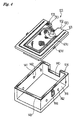
- Figs. 1 and 2 illustrate a first embodiment of the present invention.
- the papermaking mold 10 according to the first embodiment has a first member 1 and a second member 2.
- the first member 1 has a papermaking part 11.
- the papermaking part 11 has a concavity.
- the papermaking part 11 has a large number of through-holes 12 pierced therethrough to connect the surface and the reverse thereof.
- the peripheral edge of the papermaking part 11 extends outward horizontally to form a peripheral part 13.
- the edges of the peripheral part 13 form a rectangle in its plan view.
- a continuous groove 14 is made on the peripheral part 13 near and along the edges.
- the groove 14 is used as a depression mating with a projection 17 hereinafter described.
- the part of the peripheral part 13 near the papermaking part 11 and the whole papermaking part 11 are covered with a net 15.
- the second member 2 has a box shape.
- the second member 2 has a through-hole 4, which is connected to a prescribed suction means (not shown) in carrying out papermaking.
- the through-holes 12, the space 3, and the through-hole 4 connect with each other to form an interconnecting passage from the outside of the mold 10 to the inside of the papermaking part 11.
- the net 15 is provided along the surface of the papermaking part 11 and the peripheral part 11.
- the net 15 is shaped in conformity to the contour of a vertical half of a molded article to be produced.
- the net 15 is made of wire of metal, synthetic resin, etc.
- the opening size is usually about 10 to 100 mesh (JIS L-0208).
- the net 15 may have a single layer structure, a knitted structure, or a composite structure composed of two or more net layers.
- a porous material having a large number of permeating pores which is formed by electroforming can be used as the net 15, in which case the diameter of the permeating pores is about 0.05 to 2 mm.
- the net 15 fitted on the first member 1 With the net 15 fitted on the first member 1, the net 15 and the surface of the papermaking part 11 may be in close contact with each other. It is preferred, however, that the net 15 covers the papermaking part 11 with a prescribed clearance for preventing clogging by pulp fibers during papermaking and for improving papermaking efficiency.
- the papermaking mold 10 according to the present embodiment is used as paired with another half in such a manner that the papermaking parts 11 of the pair face each other so that the facing papermaking parts 11 form a cavity of a prescribed shape. A pulp slurry is injected into this cavity to deposit pulp fiber on the net. Accordingly, the pair to the papermaking mold 10, which is not illustrated, has the same structure.
- the net 15 is provided with a fixing member 16 which covers the upper side of the part 15a of the net 15 that covers the peripheral part 13 (this part of the net 15 will hereinafter be referred to as a peripheral covering part) and also surrounds the edges of the net 15. That is, the fixing member 16 is composed of a first part 16a which covers the upper side of the peripheral covering part 15a and a second part 16b which adjoins and surrounds the edges of the net 15. The thickness of the second part 16b is equal to the sum of the thickness of the first part 16a and the thickness of the peripheral covering part 15a.
- the fixing part 16 is fixed onto the peripheral part 13 by a prescribed means whereby the net 15 is fixed by the fixing member 16.
- the net 15 can be attached and detached with ease simply by fixing and removing the fixing member 16.
- the peripheral covering part 15a of the net 15 is entirely covered with the fixing member 16, the net 15 gains in strength and is thereby prevented from deformation and the like when attached or detached.
- the fixing member 16 has, on its second part 16b, a projection 17 as a mating projection on its side facing the peripheral part 13.
- the projection 17 fits into the groove 14, a mating depression, whereby the fixing member 16 is fixed to the peripheral part 13.
- the material composing the fixing member 16 is not particularly limited. As stated above, the papermaking mold 10 of the present embodiment is used as paired, and a pair of the molds 10 are mated such that the papermaking parts 13 face each other, i.e., the fixing members 16 are brought into contact with each other. Therefore it is preferred for ensuring tight contact that the fixing member 16 be capable of elastic deformation or plastic deformation.
- the fixing member 16 which is capable of elastic deformation is made of elastic materials, such as silicone rubber and epoxy resins, and the fixing member 16 which is capable of plastic deformation is made of metal or plastic materials, such as polyethylene and polypropylene.
- the fixing member 16 may be either separate from or integral with the net 15.
- the fixing member 16 is preferably integral with the net 15.
- the fixing member 16 be integrally fixed to the peripheral covering part 15a.
- the fixing member 16 which is made of such a material as silicone rubber, an epoxy resin, etc. and is integral with the peripheral covering part 15a is obtained by, for example, press-bonding the material to the peripheral covering part 15a or coating or impregnating the peripheral covering part 15a with the material.
- the fixing member 16 which is made of a metal and is integral with the peripheral covering part 15a is obtained by forming a prescribed metal shell on the peripheral covering part 15a by electroforming or a like method.
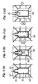
- a pulp molded article is produced by the use of the papermaking mold of the present embodiment in accordance with the method shown in Figs. 3(a) through (d).
- a pair of molds 10 and 10 are mated together so that the papermaking parts 11 face each other to form a cavity 30 of a prescribed shape, which is contoured by the two papermaking parts 11.
- a pulp slurry is poured into the cavity 30 through an opening 31 connecting to the cavity 30.
- the molds 10 and 10 are sucked from their outside and the pressure in the cavity 30 is reduced. As a result, the water content of the pulp slurry is sucked up, and the pulp fiber is deposited on the net (not shown) to form a water-containing preform 32.
- the pressing member 33 is made of an elastic material, such as urethane, fluororubber, silicone rubber or an elastomer, or a plastic material, such as polyethylene or polypropylene.
- a pressurizing fluid is fed into the pressing member 33 to inflate the pressing member 33.
- the inflated pressing member 33 presses the wet preform 32 onto the net.
- the preform 32 pressed to the net by the pressing member 33, pressing and dewatering of the preform 32 proceed while the inner shape of the net is transferred to the preform 32.
- the pressurizing fluid used to inflate the pressing member 33 includes compressed air (heated air), oil (heated oil), and other various liquids.
- the pressure for the pressurizing fluid feed is preferably 0.01 to 5 MPa, particularly 0.1 to 3 MPa.
- the pressurizing fluid is withdrawn from the pressing member 33 to shrink the pressing member 33 as shown in Fig. 3(d).
- the shrunken pressing member 33 is taken out of the cavity 30, and the molds are opened to remove the preform 32 having been pressed and dewatered to a prescribed water content.
- the removed preform 32 is subjected to a prescribed heat drying stage, where it is completely dried to give a pulp molded article.
- Figs. 4 and 5 show a second embodiment of the papermaking mold according to the present invention.
- numerical reference 101 indicates a papermaking mold.
- the papermaking mold 101 which is used as paired, has a papermaking block 102, a net 103 disposed on the surface of the papermaking block 102, and a frame 104.
- the papermaking block 102 has a block 120 which is rectangle in its plan view and a flange 121 which surrounds the block 120 from three sides.
- the frame 104 supports the papermaking block 102 from under the block 120 and the flange 121.
- the block 120 has a papermaking part 120a which is depressed in substantial conformity to a bottle container to be molded and a peripheral part 120b extending outward from the papermaking part 120a almost horizontally.
- the block 120 has a large number of interconnecting passages 120c which pierce the block 120 with their one end opening on the papermaking part 120a.
- the flange 121 overhangs horizontally in three directions.
- the upper side 121a of the overhanging flange 121 (this side will be sometimes referred to as a mating surface) is a surface on which a clamping force is exerted.
- the mating surface 121a has a groove 121b which depicts the shape of the letter "U" in its plan view.
- a sealing member 121c in this groove 121b is provided a sealing member 121c so that a pair of the papermaking molds 101 may be mated with tight seal.
- the sealing member 121c is preferably made of a material having corrosion resistance and heat resistance, such as silicone rubber, urethane rubber or fluororubber.
- the sectional shapes of the groove 121b and the sealing member 121c are not limited to those shown. Since the papermaking mold 101 is used as paired, it is preferred that either one of the paired molds have the groove 121b and the sealing member 121c.
- the block 120 and the flange 121 are formed of a first member and a second member, respectively.
- the second member is fixed to the sides of the first member by a prescribed fixing means, such as screwing, welding, and the like.
- the block 120 and the flange 121 are preferably formed of a metal such as aluminum.
- the net 103 is provided along the surface of the papermaking part 120a and the peripheral part 120b.
- the net 103 is shaped in conformity to the contour of a vertical half of a molded article to be produced.
- the part 103a of the net 103 that covers the peripheral part 120b (this part of the net 103 will hereinafter be referred to as a peripheral covering part) is disposed in a site where it does not directly receive a mold clamping force exerted in mold closure or is not damaged by the clamping force (including a case in which the net undergoes neither deformation nor damage by the mold clamping force and a case in which the mated nets are brought into contact with each other and slightly deformed in a mold clamped state but are not damaged).
- the site of the peripheral part 120b where the peripheral covering part 103a is to be disposed is lower than the upper side 121a of the flange 121 by a certain level difference d, in this embodiment.
- the level of the peripheral covering part 103a of the net 103 is lower than the mating surface 121a.
- the level difference d is decided appropriately according to the thickness of the peripheral covering part 103a of the net 103 laid along with the peripheral part 120b in a mold clamped state and the thickness of an auxiliary sealing member (or a mold clamping force buffering member) 130 hereinafter described.
- the height from the upper surface of the peripheral covering part 103a of the net 103 is preferably in a range 0 to 5.0 mm, particularly 0 to 2.0 mm.
- the upper surface of the peripheral covering part of the net and the upper surface of the flange are even (the level difference d is equal to the thickness of the peripheral covering part of the net while along with the peripheral part 120b or, in the case of a knitted net, the thickness of the peripheral covering part with the knitted wires being along with the peripheral part 120b).
- the clamping force is exerted on the upper surface of the flange but is not so directly exerted on the nets as to do damage to the nets.
- the peripheral covering parts of the nets can be brought into intimate contact without being collapsed. That is, the peripheral covering parts of the nets can be protected against damage while preventing the slurry from spewing therebetween.
- the peripheral part 103b of the net 103 is put into a gap 122 between the block 120 and the flange 121.
- a fixing plate 123 is disposed in the gap 122, which is pressed onto the side of the block 120 by a screw 124 through a threaded hole to fix the peripheral part 103b of the net 103.
- the net 103 is fabricated of metal or synthetic resin wire.
- the opening size is usually about 10 to 100 mesh (JIS L-0208).
- the net 103 may have a single layer structure, a knitted structure, or a composite structure composed of two or more net layers.
- a porous material having a large number of permeating pores which is formed by electroforming can be used as the net 103, in which case the diameter of the permeating pores is about 0.05 to 2 mm.
- An auxiliary sealing member 130 having a prescribed width is provided integrally on the peripheral covering part 103a of the net 103.
- the auxiliary sealing member 130 is preferably provided on the upper surface of the peripheral covering part 103a of the net 103 with some thickness as a part integral with the net. So far as the sealing tightness in a mold clamped state is such that a slurry is prevented from oozing from between clamped molds in the papermaking step, the height of the upper side of the auxiliary sealing member 130 is not particularly limited, but is preferably larger than the height of the mating surface 121a in a state before the molds are closed.
- the auxiliary sealing member 130 also serves as a mold clamping force buffering member which buffers the clamping force exerted on the peripheral covering part 103a of the net 103 in a mold clamped state.
- the auxiliary sealing member (or clamping force buffering member) 130 is preferably made of anticorrosive and heat-resistant materials capable of elastic deformation, such as silicone rubber, urethane rubber, fluororubber, epoxy resins, etc. Even when the net 103 is deformed while a preform is pressed and dewatered in the step of papermaking and dewatering, the auxiliary sealing member made of such an elastically deformable material is capable of following the deformation while maintaining the tight fit as described later.
- the auxiliary sealing member 130 can be formed by heat press-bonding the material to the peripheral covering part 103a or coating or impregnating the peripheral covering part 103a with the material. Since the papermaking mold 101 is used as paired, it is preferred that either one of the paired molds have the auxiliary sealing member 130. While the auxiliary sealing member is a preferred member to be provided because of the above-mentioned effects, it may be omitted where only the contact of the peripheral covering parts of the mating nets in a mold clamped state (as described above, this contact is such that the mold clamping force is not so directly exerted on the nets as to damage the nets) provides sufficient tight seal for suppressing flash formation without the aid of the auxiliary sealing member.
- the net 103 be disposed with a prescribed clearance over the papermaking part 120a for preventing clogging by pulp fibers during papermaking and for improving papermaking efficiency.
- the frame 104 has a box shape with an open top.
- the upper side wall of the frame 104 has a recess 140 into which the block 120 of the papermaking block 102 is fitted.
- the left and the right sides of the frame 104 each have suction holes 142 which connect the inside and the outside of the frame 104.
- a sealing material 143 is provided on the top edge of the frame 104 so as to secure air- and liquid-tightness when the papermaking block 102 is fitted thereto.
- the papermaking block 102 and the frame 104 are removably fixed to each other by fitting the papermaking block 102 into the frame 104 and fastening a ring 144 fixed to the side wall of the frame 104 to a hook 121d fixed to the flange 121 of the papermaking block 102.
- a changeover in kind of articles to be molded can be made simply by exchanging papermaking blocks 102 because the shape of the papermaking part 120 of the papermaking block 102 varies according to the shape of a pulp molded article to be produced. It is not necessary to make a whole papermaking mold for every shape of products.
- a hollow chamber 105 is formed therebetween.
- the hollow chamber 105 connects to the outside through the suction holes 142 and to the papermaking part 120a through the interconnecting passages 120c of the block 120.
- the papermaking mold 101 As described hereunder, the papermaking mold 101 according to this embodiment is used as paired with another half. A pair of the molds 101 are joined to mate the mating surfaces 121a thereby forming a cavity of prescribed shape, which is contoured by the two papermaking parts 120a. A pulp slurry is poured under pressure into the cavity to deposit pulp fiber on the net 103. Accordingly, while not shown, the pair to the papermaking mold 101 has the same structure.
- the papermaking mold 101 can be used, for example, in the method of producing a pulp molded article shown in Figs. 6(a) through (d). As shown in Fig. 6(a), a pair of papermaking molds 101 and 101 are joined together with the papermaking parts 120a facing each other to mate the mating surfaces 121a. A cavity C of a prescribed shape is thus formed by the two papermaking parts 120a. A pulp slurry is injected into the cavity C through an opening connecting to the cavity C. In this state, the auxiliary sealing members 130 having an elastic force are in intimate contact with each other, but the mold clamping force is exerted on the mating surfaces 121 so that the nets 103 do not directly receive such a force as to damage the nets 103. As a result, the peripheral covering part of the net undergoes substantially no deformation and can be protected from damage in repeated papermaking operation.
- the cavity C of the molds 101 and 101 is evacuated by sucking through the interconnecting passages 120c, whereby the water content of the pulp slurry is removed outside, and the pulp fiber is deposited on the net (not shown) to form a water-containing preform 106.
- the pressing member 107 is made of an elastic material, such as urethane, fluororubber, silicone rubber or an elastomer, or a plastic material, such as polyethylene or polypropylene.
- a pressurizing fluid is fed into the pressing member 107 to inflate the pressing member 107.
- the inflated pressing member 107 presses the wet preform 106 onto the net.
- the preform 106 pressed to the net by the pressing member 107, pressing and dewatering of the preform 106 proceed while the inner shape of the cavity C is transferred to the preform 106.
- the auxiliary sealing member provided on the peripheral covering part of the net follows the deformation to secure the tight seal.
- the pressurizing fluid used to inflate the pressing member 107 includes compressed air (heated air), oil (heated oil), and other various liquids.
- the pressure for the pressurizing fluid feed is preferably 0.01 to 5 MPa, particularly 0.1 to 3 MPa.
- the pressurizing fluid is withdrawn from the pressing member to shrink the pressing member as shown in Fig. 6(d).
- the shrunken pressing member is taken out of the cavity, and the molds are opened to remove the preform 106 having been dewatered to a prescribed water content.
- the removed preform 106 is subjected to a prescribed heat drying stage, where it is completely dried to give a pulp molded article.
- the peripheral covering part 103a of the net 103 is protected against direct contact with the mating surface of the complementary half in a mold clamped state.
- the peripheral covering part 103a of the net 103 hardly suffers damage from repeated mold opening and closure.
- the frequency of changing the damaged net for a new one is greatly reduced to considerably improve the working efficiency.
- the auxiliary sealing member 130 disposed on the peripheral covering part 103a of the net 103 secures tight seal, the slurry is prevented from oozing from between the mated peripheral covering parts 103a in the papermaking step.
- molded bottle articles having a satisfactory appearance with no substantial flashes on its outer surface can be obtained.
- the net 103 is removably fixed, it is easy to attach and detach the net.
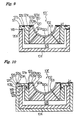
- the papermaking mold according to the present. invention can have the configurations shown in Figs. 7 to 11.
- Figs. 7 through 11 parts common to the papermaking mold 101 are given the same reference numerals, and the description thereof is omitted. Therefore, the explanation given to the papermaking mold 101 appropriately applies to the parts which are not specifically described hereunder.
- the papermaking mold 101' according to the embodiment shown in Fig. 7 has an auxiliary sealing member 130 on both the upper and the lower sides of the peripheral covering part 103a of the net 103 with some thickness as a part integral with the net.
- the damage to the net which may be caused by the friction between the peripheral part 120b and the peripheral covering part 103a of the net 103 can be suppressed as well.
- the papermaking mold 101' according to the embodiment shown in Fig. 8 has an auxiliary sealing member 130 on the lower side of the peripheral covering part 103a of the net 103 with some thickness as a part integral with the net, so that the mating peripheral covering parts 103a are brought into contact with each other without a sealing failure upon mold clamping.
- the nets come into direct contact with each other at their peripheral covering parts 103a, but because the auxiliary sealing member 130 functions as a mold clamping force buffering member, the shock of contact of the peripheral covering parts 103a can be relaxed.
- damage from direct contact between the peripheral covering parts 103a of the nets 103 and damage from friction between the peripheral covering part 103a of the net 103 and the peripheral part 120b of the block 120 can be suppressed.
- the papermaking mold 101' of the embodiment shown in Fig. 9 does not have a gap 122 as made in the papermaking mold 101. Instead, a groove 120d is formed on the surface of the peripheral part 120b, while the auxiliary sealing member 130 which is integral with the net 103 has a mating projection 130a which fits the groove 120d to fix the auxiliary sealing member 130 to the block 120.
- the net 103 can be attached and detached more easily.
- a mating member 125 is provided outside the frame 104. It is not the upper side 121a of the flange 121 but the upper edge side 125a of the mating member 125 that serves as a surface to be mated on mold clamping.
- the side 125a has a groove 125b, in which a sealing member 125c is fixedly fitted.
- the upper side 121a of the flange 121 is lower than the upper edge side 125a of the mating member 125.
- two mating nets 103 come into contact at their peripheral covering parts 103a, while the clamping force is received by the mating upper edge sides 125a.
- the net 103 does not directly receive the clamping force.
- the shock of contact is relaxed by the auxiliary sealing member 130, damage from the friction between the mating nets 103 is also reduced.
- the papermaking mold according to the embodiment shown in Fig. 11 is designed so that the peripheral covering part 103b of the papermaking net 103 may be disposed such that it would not be deformed under a mold clamping force and has a means for adjusting a mold clamping force.
- a plate 126 larger than the frame 104 is attached to the bottom (base) of the frame 104.
- the plate 126 has a plurality of through-holes 126a in at least the four corners.
- a nut 126b is put on the inner side of each of the through-holes.
- a bolt-like positioning member 126c which is male-threaded in conformity to the nut 126b is screwed in through the nut 126b, and a nut 126d is screwed tight on the positioning member 126c from the lower end of the positioning member 126c.
- the positioning member 126c has a depression 126e for positioning on its upper end surface (serving as a mating surface, on which a mold clamping force is exerted).
- the other papermaking mold 101" (the upper one in Fig. 11) has a plate 127 attached to the frame 104.
- the plate 127 has a projection 127e for positioning which fits the depression 126e for positioning.
- the mold clamping force can be adjusted by the position of the positioning member 126c screwed in. That is, the means for adjusting a mold clamping force comprises the plates 126 and 127, the nuts 126b and 126d, and the positioning members 126c.
- the positioning members 126c may be threaded over the whole length thereof.
- the molding clamping force can easily be adjusted so that the peripheral covering part 103a of the papermaking net 103 is not deformed and that the peripheral covering part 103a (or an auxiliary sealing member 130 if provided on the peripheral covering part 103b) may secure tight seal to provide a flash-free molded article.
- the structure makes it possible to carry out positioning with good accuracy in clamping the molds.
- the present invention is not limited to the foregoing embodiments.
- the fixing member 16 in the first embodiment wherein the fixing member 16 is fixed to the peripheral part 13 by the engagement of the mating projection and the mating depression, the fixing member 16 can be fixed to the peripheral part 13 by screwing, adhesion with a strippable adhesive, or a like means.
- a mating depression may be formed on the second part of the fixing member 16, and a mating projection may be formed on the peripheral part 13.
- the block 120 having the papermaking part 120a and the upper side of the flange 121, on which a mold clamping force is exerted be formed of a first member and a second member, respectively, it is possible to form these parts integrally.
- auxiliary sealing member be integral with the net and be disposed on the peripheral part 120b of the block 120, it may be fixed directly into a groove made on the peripheral part 120b of the block 120 or may be adhered to the peripheral part.
- a depression and a projection for positioning are formed on the positioning member 126c and the facing plate 127, respectively.
- the depression and the projection for positioning may be formed on the mating positions of the upper side of the flanges.
- the papermaking mold according to the present invention is also applicable to a press mold for papermaking which is composed of a male mold and a female mold.
- the present invention provides a papermaking mold the net of which can be attached and detached with improved ease. Where a fixing member is integrally fixed to the net, the net has increased strength and is prevented from deformation and the like when attached or detached.
- the papermaking mold of the present invention is prevented from damaging the net thereof when used for papermaking repeatedly.
Landscapes
- Engineering & Computer Science (AREA)
- Manufacturing & Machinery (AREA)
- Paper (AREA)
Abstract
A papermaking mold (10) which comprises a papermaking part (11) of a prescribed shape, a peripheral part (13) extending outward from the peripheral edge of the papermaking part (11), and a net (15) covering the papermaking part (11) and at least part of the peripheral part (13), wherein a fixing member (16) is disposed on the periphery of the net (15), and the fixing member (16) is fixed to the peripheral part (13) to fix the net (15) by the fixing member (16). <IMAGE>
Description
The present invention relates to a papermaking mold used to produce pulp
molded articles.
A papermaking mold used to manufacture pulp molded articles usually has a net
on the inner surface of its papermaking part. The net is generally fixed to the mold by
welding or with metal wire, etc. Otherwise, the net would move out of a prescribed
position during papermaking by the pressure or the flow of a pulp slurry injected, etc.,
which results in a failure to obtain a molded article of a desired shape or results in a
non-uniform thickness of the resulting molded article.
As a mold with a net is used repeatedly for producing molded articles, pulp fiber
is adhered and accumulated on the net to cause unevenness in thickness of molded
articles or impair the appearance of molded articles. Thus, it is necessary for the net to
be removed and cleaned. However, where the net is fixed by welding, it is not easy to
remove the net. Where it is fixed with wire, etc., removal is possible but laborious.
In a conventional papermaking mold, a mold clamping force is applied to the
peripheral part of the mold where the papermaking net is disposed so that the force is
directly exerted on the net. As a result, the net is deformed on clamping and gradually
damaged from repetition of papermaking and eventually needs an exchange. Where,
in particular, a wet preform after papermaking and dewatering is transferred from the
papermaking mold to a drying mold by purging with compressed air and suction, the
frequency of mold opening and closure increases, and the part of the net which covers
the peripheral part of the mold which extends outward from the papermaking part
suffers considerable damage. This problem occurs in conjunction with the above-mentioned
difficulty of net exchange where the net is fixed to the mold by welding or
with wire, etc. Therefore a papermaking mold of which the net hardly suffers damage
from repeated use of the mold has been desired.
Accordingly, an object of the present invention is to provide a papermaking
mold the net of which can be attached and detached with improved ease.
Another object of the present invention is to provide a papermaking mold which reduces damage to the net thereof when used repeatedly.
Another object of the present invention is to provide a papermaking mold which reduces damage to the net thereof when used repeatedly.
The present invention accomplishes the above objects by providing a
papermaking mold which comprises a papermaking part of a prescribed shape, a
peripheral part extending outward from the peripheral edge of the papermaking part,
and a net covering the papermaking part and at least part of the peripheral part, wherein
a fixing member is disposed on the periphery of the net, and the fixing member is fixed
to the peripheral part to fix the net by the fixing member.
The present invention also accomplishes the above objects by providing a
papermaking mold which comprises a papermaking part of a prescribed shape, a
peripheral part extending outward from the papermaking part, and a papermaking net
covering the papermaking part and at least part of the peripheral part, wherein the part
of the net which covers the peripheral part is disposed in the site where it does not
receive a mold clamping force or it is not damaged by a mold clamping force.
The present invention will be described based on the preferred embodiments
with reference to the accompanying drawings.
Figs. 1 and 2 illustrate a first embodiment of the present invention. As shown
in these figures, the papermaking mold 10 according to the first embodiment has a first
member 1 and a second member 2. The first member 1 has a papermaking part 11.
The papermaking part 11 has a concavity. The papermaking part 11 has a large
number of through-holes 12 pierced therethrough to connect the surface and the reverse
thereof. The peripheral edge of the papermaking part 11 extends outward horizontally
to form a peripheral part 13. The edges of the peripheral part 13 form a rectangle in its
plan view. A continuous groove 14 is made on the peripheral part 13 near and along
the edges. The groove 14 is used as a depression mating with a projection 17
hereinafter described. The part of the peripheral part 13 near the papermaking part 11
and the whole papermaking part 11 are covered with a net 15.
The second member 2 has a box shape. When the first member 1 is fitted into
the second member 2, there is formed a prescribed space 3 between the first member 1
and the second member 2. The second member 2 has a through-hole 4, which is
connected to a prescribed suction means (not shown) in carrying out papermaking.
Thus, the through-holes 12, the space 3, and the through-hole 4 connect with each other
to form an interconnecting passage from the outside of the mold 10 to the inside of the
papermaking part 11.
The net 15 is provided along the surface of the papermaking part 11 and the
peripheral part 11. The net 15 is shaped in conformity to the contour of a vertical half
of a molded article to be produced. The net 15 is made of wire of metal, synthetic
resin, etc. The opening size is usually about 10 to 100 mesh (JIS L-0208). The net
15 may have a single layer structure, a knitted structure, or a composite structure
composed of two or more net layers. A porous material having a large number of
permeating pores which is formed by electroforming can be used as the net 15, in which
case the diameter of the permeating pores is about 0.05 to 2 mm.
With the net 15 fitted on the first member 1, the net 15 and the surface of the
papermaking part 11 may be in close contact with each other. It is preferred, however,
that the net 15 covers the papermaking part 11 with a prescribed clearance for
preventing clogging by pulp fibers during papermaking and for improving papermaking
efficiency.
The papermaking mold 10 according to the present embodiment is used as
paired with another half in such a manner that the papermaking parts 11 of the pair face
each other so that the facing papermaking parts 11 form a cavity of a prescribed shape.
A pulp slurry is injected into this cavity to deposit pulp fiber on the net. Accordingly,
the pair to the papermaking mold 10, which is not illustrated, has the same structure.
The net 15 is provided with a fixing member 16 which covers the upper side of
the part 15a of the net 15 that covers the peripheral part 13 (this part of the net 15 will
hereinafter be referred to as a peripheral covering part) and also surrounds the edges of
the net 15. That is, the fixing member 16 is composed of a first part 16a which covers
the upper side of the peripheral covering part 15a and a second part 16b which adjoins
and surrounds the edges of the net 15. The thickness of the second part 16b is equal to
the sum of the thickness of the first part 16a and the thickness of the peripheral covering
part 15a. The fixing part 16 is fixed onto the peripheral part 13 by a prescribed means
whereby the net 15 is fixed by the fixing member 16. In this manner, there is no need
to directly fix the net 15 itself, and the net 15 can be attached and detached with ease
simply by fixing and removing the fixing member 16. In this embodiment, since the
peripheral covering part 15a of the net 15 is entirely covered with the fixing member 16,
the net 15 gains in strength and is thereby prevented from deformation and the like
when attached or detached.
The fixing member 16 has, on its second part 16b, a projection 17 as a mating
projection on its side facing the peripheral part 13. The projection 17 fits into the
groove 14, a mating depression, whereby the fixing member 16 is fixed to the peripheral
part 13.
The material composing the fixing member 16 is not particularly limited. As
stated above, the papermaking mold 10 of the present embodiment is used as paired,
and a pair of the molds 10 are mated such that the papermaking parts 13 face each other,
i.e., the fixing members 16 are brought into contact with each other. Therefore it is
preferred for ensuring tight contact that the fixing member 16 be capable of elastic
deformation or plastic deformation. The fixing member 16 which is capable of elastic
deformation is made of elastic materials, such as silicone rubber and epoxy resins, and
the fixing member 16 which is capable of plastic deformation is made of metal or
plastic materials, such as polyethylene and polypropylene.
The fixing member 16 may be either separate from or integral with the net 15.
For strengthening the net 15, the fixing member 16 is preferably integral with the net
15. Where the fixing member 16 and the net 15 are integral with each other, it is
preferred that the fixing member 16 be integrally fixed to the peripheral covering part
15a. The fixing member 16 which is made of such a material as silicone rubber, an
epoxy resin, etc. and is integral with the peripheral covering part 15a is obtained by, for
example, press-bonding the material to the peripheral covering part 15a or coating or
impregnating the peripheral covering part 15a with the material. The fixing member
16 which is made of a metal and is integral with the peripheral covering part 15a is
obtained by forming a prescribed metal shell on the peripheral covering part 15a by
electroforming or a like method.
A pulp molded article is produced by the use of the papermaking mold of the
present embodiment in accordance with the method shown in Figs. 3(a) through (d).
As shown in Fig. 3(a), a pair of molds 10 and 10 are mated together so that the
papermaking parts 11 face each other to form a cavity 30 of a prescribed shape, which is
contoured by the two papermaking parts 11. A pulp slurry is poured into the cavity 30
through an opening 31 connecting to the cavity 30. The molds 10 and 10 are sucked
from their outside and the pressure in the cavity 30 is reduced. As a result, the water
content of the pulp slurry is sucked up, and the pulp fiber is deposited on the net (not
shown) to form a water-containing preform 32.
On completion of pouring a prescribed amount of the pulp slurry, pouring is
stopped, and the cavity 30 is completely sucked for dewatering. An inflatable hollow
pressing member 33 is inserted into the cavity 30 while continuing sucking and
evacuating the cavity 30 as shown in Fig. 3(b). The pressing member 33 is made of an
elastic material, such as urethane, fluororubber, silicone rubber or an elastomer, or a
plastic material, such as polyethylene or polypropylene.
As shown in Fig. 3(c), a pressurizing fluid is fed into the pressing member 33 to
inflate the pressing member 33. The inflated pressing member 33 presses the wet
preform 32 onto the net. The preform 32 pressed to the net by the pressing member
33, pressing and dewatering of the preform 32 proceed while the inner shape of the net
is transferred to the preform 32. The pressurizing fluid used to inflate the pressing
member 33 includes compressed air (heated air), oil (heated oil), and other various
liquids. The pressure for the pressurizing fluid feed is preferably 0.01 to 5 MPa,
particularly 0.1 to 3 MPa.
After the preform 32 is pressed and dewatered to a prescribed water content, and
after the inner shape of the cavity 30 is sufficiently transferred to the preform 32, the
pressurizing fluid is withdrawn from the pressing member 33 to shrink the pressing
member 33 as shown in Fig. 3(d). The shrunken pressing member 33 is taken out of
the cavity 30, and the molds are opened to remove the preform 32 having been pressed
and dewatered to a prescribed water content. The removed preform 32 is subjected to
a prescribed heat drying stage, where it is completely dried to give a pulp molded
article.
Figs. 4 and 5 show a second embodiment of the papermaking mold according to
the present invention. In these figures, numerical reference 101 indicates a
papermaking mold.
As illustrated in Fig. 4, the papermaking mold 101, which is used as paired, has
a papermaking block 102, a net 103 disposed on the surface of the papermaking block
102, and a frame 104. The papermaking block 102 has a block 120 which is rectangle
in its plan view and a flange 121 which surrounds the block 120 from three sides. The
frame 104 supports the papermaking block 102 from under the block 120 and the flange
121.
As shown in Fig. 5, the block 120 has a papermaking part 120a which is
depressed in substantial conformity to a bottle container to be molded and a peripheral
part 120b extending outward from the papermaking part 120a almost horizontally.
The block 120 has a large number of interconnecting passages 120c which pierce the
block 120 with their one end opening on the papermaking part 120a.
The flange 121 overhangs horizontally in three directions. In this embodiment,
the upper side 121a of the overhanging flange 121 (this side will be sometimes referred
to as a mating surface) is a surface on which a clamping force is exerted. The mating
surface 121a has a groove 121b which depicts the shape of the letter "U" in its plan
view. In this groove 121b is provided a sealing member 121c so that a pair of the
papermaking molds 101 may be mated with tight seal. The sealing member 121c is
preferably made of a material having corrosion resistance and heat resistance, such as
silicone rubber, urethane rubber or fluororubber. The sectional shapes of the groove
121b and the sealing member 121c are not limited to those shown. Since the
papermaking mold 101 is used as paired, it is preferred that either one of the paired
molds have the groove 121b and the sealing member 121c.
In the papermaking mold 101 according to the present embodiment, the block
120 and the flange 121 are formed of a first member and a second member,
respectively. The second member is fixed to the sides of the first member by a
prescribed fixing means, such as screwing, welding, and the like. The block 120 and
the flange 121 are preferably formed of a metal such as aluminum.
The net 103 is provided along the surface of the papermaking part 120a and the
peripheral part 120b. The net 103 is shaped in conformity to the contour of a vertical
half of a molded article to be produced. The part 103a of the net 103 that covers the
peripheral part 120b (this part of the net 103 will hereinafter be referred to as a
peripheral covering part) is disposed in a site where it does not directly receive a mold
clamping force exerted in mold closure or is not damaged by the clamping force
(including a case in which the net undergoes neither deformation nor damage by the
mold clamping force and a case in which the mated nets are brought into contact with
each other and slightly deformed in a mold clamped state but are not damaged). More
specifically, the site of the peripheral part 120b where the peripheral covering part 103a
is to be disposed is lower than the upper side 121a of the flange 121 by a certain level
difference d, in this embodiment. In a mold clamped state, the level of the peripheral
covering part 103a of the net 103 is lower than the mating surface 121a. The level
difference d is decided appropriately according to the thickness of the peripheral
covering part 103a of the net 103 laid along with the peripheral part 120b in a mold
clamped state and the thickness of an auxiliary sealing member (or a mold clamping
force buffering member) 130 hereinafter described. From the standpoint of preventing
flash formation, the height from the upper surface of the peripheral covering part 103a
of the net 103 (in cases where an auxiliary sealing member (or a mold clamping force
buffering member) is provided on the upper side of the peripheral covering part 103a as
in the present embodiment, the height from the surface with no such an auxiliary sealing
member) to the upper side 121a of the flange is preferably in a range 0 to 5.0 mm,
particularly 0 to 2.0 mm. When the height from the upper surface of the peripheral
covering part to the height of the upper surface of the flange is 0 mm, the upper surface
of the peripheral covering part of the net and the upper surface of the flange are even
(the level difference d is equal to the thickness of the peripheral covering part of the net
while along with the peripheral part 120b or, in the case of a knitted net, the thickness of
the peripheral covering part with the knitted wires being along with the peripheral part
120b). In this case, although the peripheral covering parts of the two nets come into
contact with each other in a mold clamped state, the clamping force is exerted on the
upper surface of the flange but is not so directly exerted on the nets as to do damage to
the nets. Therefore, in a mold clamped state, the peripheral covering parts of the nets
can be brought into intimate contact without being collapsed. That is, the peripheral
covering parts of the nets can be protected against damage while preventing the slurry
from spewing therebetween. In this case, it is particularly preferred to provide the
upper surface 121a of the flange 121 with the above-described sealing member 121c as
in the present embodiment.
The peripheral part 103b of the net 103 is put into a gap 122 between the block
120 and the flange 121. A fixing plate 123 is disposed in the gap 122, which is
pressed onto the side of the block 120 by a screw 124 through a threaded hole to fix the
peripheral part 103b of the net 103. This manner of fixing the net 103 makes it easy to
attach and detach the net 103, should the net undergo damage.
The net 103 is fabricated of metal or synthetic resin wire. The opening size is
usually about 10 to 100 mesh (JIS L-0208). The net 103 may have a single layer
structure, a knitted structure, or a composite structure composed of two or more net
layers. A porous material having a large number of permeating pores which is formed
by electroforming can be used as the net 103, in which case the diameter of the
permeating pores is about 0.05 to 2 mm.
An auxiliary sealing member 130 having a prescribed width is provided
integrally on the peripheral covering part 103a of the net 103. The auxiliary sealing
member 130 is preferably provided on the upper surface of the peripheral covering part
103a of the net 103 with some thickness as a part integral with the net. So far as the
sealing tightness in a mold clamped state is such that a slurry is prevented from oozing
from between clamped molds in the papermaking step, the height of the upper side of
the auxiliary sealing member 130 is not particularly limited, but is preferably larger than
the height of the mating surface 121a in a state before the molds are closed. The
auxiliary sealing member 130 also serves as a mold clamping force buffering member
which buffers the clamping force exerted on the peripheral covering part 103a of the net
103 in a mold clamped state. The auxiliary sealing member (or clamping force
buffering member) 130 is preferably made of anticorrosive and heat-resistant materials
capable of elastic deformation, such as silicone rubber, urethane rubber, fluororubber,
epoxy resins, etc. Even when the net 103 is deformed while a preform is pressed and
dewatered in the step of papermaking and dewatering, the auxiliary sealing member
made of such an elastically deformable material is capable of following the deformation
while maintaining the tight fit as described later. The auxiliary sealing member 130
can be formed by heat press-bonding the material to the peripheral covering part 103a
or coating or impregnating the peripheral covering part 103a with the material. Since
the papermaking mold 101 is used as paired, it is preferred that either one of the paired
molds have the auxiliary sealing member 130. While the auxiliary sealing member is a
preferred member to be provided because of the above-mentioned effects, it may be
omitted where only the contact of the peripheral covering parts of the mating nets in a
mold clamped state (as described above, this contact is such that the mold clamping
force is not so directly exerted on the nets as to damage the nets) provides sufficient
tight seal for suppressing flash formation without the aid of the auxiliary sealing
member.
It is preferred that the net 103 be disposed with a prescribed clearance over the
papermaking part 120a for preventing clogging by pulp fibers during papermaking and
for improving papermaking efficiency.
The frame 104 has a box shape with an open top. The upper side wall of the
frame 104 has a recess 140 into which the block 120 of the papermaking block 102 is
fitted. The left and the right sides of the frame 104 each have suction holes 142 which
connect the inside and the outside of the frame 104. A sealing material 143 is
provided on the top edge of the frame 104 so as to secure air- and liquid-tightness when
the papermaking block 102 is fitted thereto.
The papermaking block 102 and the frame 104 are removably fixed to each
other by fitting the papermaking block 102 into the frame 104 and fastening a ring 144
fixed to the side wall of the frame 104 to a hook 121d fixed to the flange 121 of the
papermaking block 102. Seeing that the papermaking block 102 is removably fixed to
the frame 104, a changeover in kind of articles to be molded can be made simply by
exchanging papermaking blocks 102 because the shape of the papermaking part 120 of
the papermaking block 102 varies according to the shape of a pulp molded article to be
produced. It is not necessary to make a whole papermaking mold for every shape of
products.
With the papermaking block 102 fitted into the frame 104, a hollow chamber
105 is formed therebetween. The hollow chamber 105 connects to the outside through
the suction holes 142 and to the papermaking part 120a through the interconnecting
passages 120c of the block 120.
As described hereunder, the papermaking mold 101 according to this
embodiment is used as paired with another half. A pair of the molds 101 are joined to
mate the mating surfaces 121a thereby forming a cavity of prescribed shape, which is
contoured by the two papermaking parts 120a. A pulp slurry is poured under pressure
into the cavity to deposit pulp fiber on the net 103. Accordingly, while not shown, the
pair to the papermaking mold 101 has the same structure.
The papermaking mold 101 can be used, for example, in the method of
producing a pulp molded article shown in Figs. 6(a) through (d). As shown in Fig.
6(a), a pair of papermaking molds 101 and 101 are joined together with the
papermaking parts 120a facing each other to mate the mating surfaces 121a. A cavity
C of a prescribed shape is thus formed by the two papermaking parts 120a. A pulp
slurry is injected into the cavity C through an opening connecting to the cavity C. In
this state, the auxiliary sealing members 130 having an elastic force are in intimate
contact with each other, but the mold clamping force is exerted on the mating surfaces
121 so that the nets 103 do not directly receive such a force as to damage the nets 103.
As a result, the peripheral covering part of the net undergoes substantially no
deformation and can be protected from damage in repeated papermaking operation.
The cavity C of the molds 101 and 101 is evacuated by sucking through the
interconnecting passages 120c, whereby the water content of the pulp slurry is removed
outside, and the pulp fiber is deposited on the net (not shown) to form a water-containing
preform 106.
On completion of injecting a prescribed amount of the pulp slurry, injection is
stopped, and the cavity C is completely sucked for dewatering through the
interconnecting passages 120c. An inflatable hollow pressing member 107 is inserted
into the cavity C while continuing sucking and evacuating the cavity C through the
passages 120c as shown in Fig. 6(b). The pressing member 107 is made of an elastic
material, such as urethane, fluororubber, silicone rubber or an elastomer, or a plastic
material, such as polyethylene or polypropylene.
As shown in Fig. 6(c), a pressurizing fluid is fed into the pressing member 107
to inflate the pressing member 107. The inflated pressing member 107 presses the wet
preform 106 onto the net. The preform 106 pressed to the net by the pressing member
107, pressing and dewatering of the preform 106 proceed while the inner shape of the
cavity C is transferred to the preform 106. Even if the net is elastically deformed
during this step, the auxiliary sealing member provided on the peripheral covering part
of the net follows the deformation to secure the tight seal. Thus, the inner shape of the
cavity C can be transferred without flash formation. The pressurizing fluid used to
inflate the pressing member 107 includes compressed air (heated air), oil (heated oil),
and other various liquids. The pressure for the pressurizing fluid feed is preferably
0.01 to 5 MPa, particularly 0.1 to 3 MPa.
After the preform 106 is pressed and dewatered to a prescribed water content,
and after the inner shape of the cavity C is sufficiently transferred to the preform 106,
the pressurizing fluid is withdrawn from the pressing member to shrink the pressing
member as shown in Fig. 6(d). The shrunken pressing member is taken out of the
cavity, and the molds are opened to remove the preform 106 having been dewatered to a
prescribed water content. The removed preform 106 is subjected to a prescribed heat
drying stage, where it is completely dried to give a pulp molded article.
With the papermaking mold 101 of the present embodiment, the peripheral
covering part 103a of the net 103 is protected against direct contact with the mating
surface of the complementary half in a mold clamped state. As a result, the peripheral
covering part 103a of the net 103 hardly suffers damage from repeated mold opening
and closure. The frequency of changing the damaged net for a new one is greatly
reduced to considerably improve the working efficiency. Further, because the
auxiliary sealing member 130 disposed on the peripheral covering part 103a of the net
103 secures tight seal, the slurry is prevented from oozing from between the mated
peripheral covering parts 103a in the papermaking step. As a result, molded bottle
articles having a satisfactory appearance with no substantial flashes on its outer surface
can be obtained. Furthermore, since the net 103 is removably fixed, it is easy to attach
and detach the net.
The present invention is not limited to the aforementioned embodiments. For
example, the papermaking mold according to the present. invention can have the
configurations shown in Figs. 7 to 11. In Figs. 7 through 11, parts common to the
papermaking mold 101 are given the same reference numerals, and the description
thereof is omitted. Therefore, the explanation given to the papermaking mold 101
appropriately applies to the parts which are not specifically described hereunder.
The papermaking mold 101' according to the embodiment shown in Fig. 7 has
an auxiliary sealing member 130 on both the upper and the lower sides of the peripheral
covering part 103a of the net 103 with some thickness as a part integral with the net.
In this embodiment the damage to the net which may be caused by the friction between
the peripheral part 120b and the peripheral covering part 103a of the net 103 can be
suppressed as well.
The papermaking mold 101' according to the embodiment shown in Fig. 8 has
an auxiliary sealing member 130 on the lower side of the peripheral covering part 103a
of the net 103 with some thickness as a part integral with the net, so that the mating
peripheral covering parts 103a are brought into contact with each other without a
sealing failure upon mold clamping. In this embodiment the nets come into direct
contact with each other at their peripheral covering parts 103a, but because the auxiliary
sealing member 130 functions as a mold clamping force buffering member, the shock of
contact of the peripheral covering parts 103a can be relaxed. As a result, damage from
direct contact between the peripheral covering parts 103a of the nets 103 and damage
from friction between the peripheral covering part 103a of the net 103 and the
peripheral part 120b of the block 120 can be suppressed.
The papermaking mold 101' of the embodiment shown in Fig. 9 does not have a
gap 122 as made in the papermaking mold 101. Instead, a groove 120d is formed on
the surface of the peripheral part 120b, while the auxiliary sealing member 130 which is
integral with the net 103 has a mating projection 130a which fits the groove 120d to fix
the auxiliary sealing member 130 to the block 120. By this structure, the net 103 can
be attached and detached more easily.
In the papermaking mold 101' of the embodiment shown in Fig. 10, an alteration
is made to the position where to dispose the sealing member on the surface to be mated
on mold clamping so that the peripheral covering part 103b of the papermaking net 103
may be disposed such that it would not be deformed under the mold clamping force.
That is, a mating member 125 is provided outside the frame 104. It is not the upper
side 121a of the flange 121 but the upper edge side 125a of the mating member 125 that
serves as a surface to be mated on mold clamping. The side 125a has a groove 125b,
in which a sealing member 125c is fixedly fitted. The upper side 121a of the flange
121 is lower than the upper edge side 125a of the mating member 125. On mold
clamping, two mating nets 103 come into contact at their peripheral covering parts
103a, while the clamping force is received by the mating upper edge sides 125a. As a
result, the net 103 does not directly receive the clamping force. Further, since the
shock of contact is relaxed by the auxiliary sealing member 130, damage from the
friction between the mating nets 103 is also reduced.
The papermaking mold according to the embodiment shown in Fig. 11 is
designed so that the peripheral covering part 103b of the papermaking net 103 may be
disposed such that it would not be deformed under a mold clamping force and has a
means for adjusting a mold clamping force. As for the papermaking mold 101' which
is one of the paired papermaking molds (the lower one in Fig. 11), a plate 126 larger
than the frame 104 is attached to the bottom (base) of the frame 104. The plate 126
has a plurality of through-holes 126a in at least the four corners. A nut 126b is put on
the inner side of each of the through-holes. A bolt-like positioning member 126c
which is male-threaded in conformity to the nut 126b is screwed in through the nut
126b, and a nut 126d is screwed tight on the positioning member 126c from the lower
end of the positioning member 126c. The positioning member 126c has a depression
126e for positioning on its upper end surface (serving as a mating surface, on which a
mold clamping force is exerted). The other papermaking mold 101" (the upper one in
Fig. 11) has a plate 127 attached to the frame 104. The plate 127 has a projection 127e
for positioning which fits the depression 126e for positioning. With this structure,
even after the papermaking net 103 is fixed onto the block 120, the mold clamping force
can be adjusted by the position of the positioning member 126c screwed in. That is,
the means for adjusting a mold clamping force comprises the plates 126 and 127, the
nuts 126b and 126d, and the positioning members 126c. The positioning members
126c may be threaded over the whole length thereof.
With this structure, even after the papermaking net 103 is fixed, the molding
clamping force can easily be adjusted so that the peripheral covering part 103a of the
papermaking net 103 is not deformed and that the peripheral covering part 103a (or an
auxiliary sealing member 130 if provided on the peripheral covering part 103b) may
secure tight seal to provide a flash-free molded article. Having the depression 126e
and the projection 127e, the structure makes it possible to carry out positioning with
good accuracy in clamping the molds.
The present invention is not limited to the foregoing embodiments. For
example, in the first embodiment wherein the fixing member 16 is fixed to the
peripheral part 13 by the engagement of the mating projection and the mating
depression, the fixing member 16 can be fixed to the peripheral part 13 by screwing,
adhesion with a strippable adhesive, or a like means.
In the first embodiment, a mating depression may be formed on the second part
of the fixing member 16, and a mating projection may be formed on the peripheral part
13.
Although it is preferred that the block 120 having the papermaking part 120a
and the upper side of the flange 121, on which a mold clamping force is exerted, be
formed of a first member and a second member, respectively, it is possible to form these
parts integrally.
While it is preferred that the auxiliary sealing member be integral with the net
and be disposed on the peripheral part 120b of the block 120, it may be fixed directly
into a groove made on the peripheral part 120b of the block 120 or may be adhered to
the peripheral part.
In the embodiment shown in Fig. 11, a depression and a projection for
positioning are formed on the positioning member 126c and the facing plate 127,
respectively. Unlike this, in cases where the upper side 121a of the flange 121 serves
as a mating surface (a surface on which a mold clamping force is exerted), the
depression and the projection for positioning may be formed on the mating positions of
the upper side of the flanges.
The papermaking mold according to the present invention is also applicable to a
press mold for papermaking which is composed of a male mold and a female mold.
The present invention provides a papermaking mold the net of which can be
attached and detached with improved ease.
Where a fixing member is integrally fixed to the net, the net has increased strength and is prevented from deformation and the like when attached or detached.
The papermaking mold of the present invention is prevented from damaging the net thereof when used for papermaking repeatedly.
Where a fixing member is integrally fixed to the net, the net has increased strength and is prevented from deformation and the like when attached or detached.
The papermaking mold of the present invention is prevented from damaging the net thereof when used for papermaking repeatedly.
Claims (10)
- A papermaking mold which comprises a papermaking part of a prescribed shape, a peripheral part extending outward from the peripheral edge of said papermaking part, and a net covering said papermaking part and at least part of said peripheral part, wherein a fixing member is disposed on the periphery of said net, and said fixing member is fixed to said peripheral part to fix said net by said fixing member.
- The papermaking mold according to claim 1, wherein said fixing member is integrally fixed to the part of said net that covers said peripheral part.
- The papermaking mold according to claim 1, wherein said fixing member has a mating projection which fits in a mating depression made on said peripheral part to fix said fixing member to said peripheral part.
- The papermaking mold according to claim 1, which is used as paired with another one in such a manner that the papermaking parts of the pair face each other and the fixing members of the pair are brought into contact with each other.
- The papermaking mold according to claim 1, which is used as paired with another one in such a manner that the papermaking parts of the pair face each other so that said papermaking parts form a cavity of a prescribed shape in which a pulp slurry is to be injected to deposit pulp fiber on said net.
- A papermaking mold which comprises a papermaking part of a prescribed shape, a peripheral part extending outward from said papermaking part, and a papermaking net covering said papermaking part and at least part of said peripheral part, wherein said part of the net which covers said peripheral part is disposed in the site where it does not receive a mold clamping force or it is not damaged by a mold clamping force.
- The papermaking mold according to claim 6, wherein said site of said peripheral part where said part of the net which covers said peripheral part is to be disposed is lower than a surface on which a mold clamping force is to be exerted by a certain level difference.
- The papermaking mold according to claim 6, which has a means for adjusting a mold clamping force.
- The papermaking mold according to claim 6, wherein a sealing member is provided on said surface on which a mold clamping force is to be exerted.
- The papermaking mold according to claim 6, wherein an auxiliary sealing member or a mold clamping force buffering member is provided on said part of the net which covers said peripheral part or on said site of disposition.
Applications Claiming Priority (3)
| Application Number | Priority Date | Filing Date | Title |
|---|---|---|---|
| JP15564299 | 1999-06-02 | ||
| JP11155642A JP2000345500A (en) | 1999-06-02 | 1999-06-02 | Papermaking mold |
| PCT/JP2000/003475 WO2000075428A1 (en) | 1999-06-02 | 2000-05-30 | Mold for paper-making |
Publications (2)
| Publication Number | Publication Date |
|---|---|
| EP1199406A1 true EP1199406A1 (en) | 2002-04-24 |
| EP1199406A4 EP1199406A4 (en) | 2007-11-07 |
Family
ID=15610443
Family Applications (1)
| Application Number | Title | Priority Date | Filing Date |
|---|---|---|---|
| EP00931611A Withdrawn EP1199406A4 (en) | 1999-06-02 | 2000-05-30 | Mold for paper-making |
Country Status (5)
| Country | Link |
|---|---|
| US (1) | US6860461B1 (en) |
| EP (1) | EP1199406A4 (en) |
| JP (1) | JP2000345500A (en) |
| CN (1) | CN1183299C (en) |
| WO (1) | WO2000075428A1 (en) |
Cited By (2)
| Publication number | Priority date | Publication date | Assignee | Title |
|---|---|---|---|---|
| GB2392409A (en) * | 2002-08-29 | 2004-03-03 | Verna Ltd | Moulding apparatus |
| US7972129B2 (en) * | 2005-09-16 | 2011-07-05 | O'donoghue Joseph | Compound tooling system for molding applications |
Families Citing this family (12)
| Publication number | Priority date | Publication date | Assignee | Title |
|---|---|---|---|---|
| JP3512699B2 (en) | 2000-03-06 | 2004-03-31 | 花王株式会社 | Method for producing pulp molded article |
| US7014452B2 (en) * | 2003-05-08 | 2006-03-21 | Eppsi Corp. | Mold assembly for making paper products |
| US7507315B1 (en) * | 2005-01-28 | 2009-03-24 | Maxine Seelenbinder-Apke | Paper making apparatus and method |
| CN102071602B (en) * | 2010-10-13 | 2013-03-27 | 杭州珂瑞特机械制造有限公司 | Aluminum-casting milling-hole type demoulding wheel and cotton-core forming device thereof |
| US10214860B1 (en) | 2015-02-04 | 2019-02-26 | Ann Alaia Woods | Hinged mould-and-deckle tool for making paper by hand |
| DE102017214469A1 (en) * | 2017-08-18 | 2019-02-21 | Sig Technology Ag | A method of manufacturing a container from a container blank, in particular by reducing a height of the container blank |
| CN108914708A (en) * | 2018-08-20 | 2018-11-30 | 永发(江苏)模塑包装科技有限公司 | A kind of secondary packet web frame and packet network method of midge mold |
| CN109403158A (en) * | 2018-11-23 | 2019-03-01 | 长沙云聚汇科技有限公司 | A kind of device preparing latticed non-woven fabrics |
| US20240218606A1 (en) * | 2019-10-14 | 2024-07-04 | Kiefel Gmbh | Mold body with integrated connection unit for a pre-pressing tool, and pre-pressing tool |
| US20240218607A1 (en) * | 2019-10-14 | 2024-07-04 | Kiefel Gmbh | Mold body with varying thickness for a pre-pressing tool, and pre-pressing tool |
| US20240218597A1 (en) * | 2019-10-14 | 2024-07-04 | Kiefel Gmbh | Mold body for a pre-pressing tool, and pre-pressing tool |
| US11421388B1 (en) * | 2019-11-01 | 2022-08-23 | Henry Molded Products, Inc. | Single-walled disposable cooler made of fiber-based material and method of making a single-walled disposable cooler made of fiber-based material |
Family Cites Families (15)
| Publication number | Priority date | Publication date | Assignee | Title |
|---|---|---|---|---|
| US2105593A (en) * | 1936-06-18 | 1938-01-18 | William H Hatton | Apparatus for molding pulp bodies |
| US2149878A (en) * | 1936-08-27 | 1939-03-07 | Harvey V Mitchell | Pulp molding |
| US2471932A (en) * | 1941-12-23 | 1949-05-31 | Merle P Chaplin | Molded pulp apparatus and method |
| US2600265A (en) * | 1947-03-27 | 1952-06-10 | Canal Nat Bank Of Portland | Pulp molding die |
| US2961043A (en) | 1957-01-22 | 1960-11-22 | Diamond National Corp | Pulp molding apparatus |
| US3802963A (en) * | 1971-02-11 | 1974-04-09 | Int Paper Co | Pulp molding system employing suction box which prevents rewetting of the molded products |
| US4014739A (en) | 1974-05-09 | 1977-03-29 | International Paper Company | Mold construction having removable base member |
| US3894679A (en) | 1974-06-21 | 1975-07-15 | Diamond Int Corp | High strength open bottom packaging tray |
| GB8403507D0 (en) | 1984-02-10 | 1984-03-14 | Vernon & Co Pulp Prod | Moulding |
| DE3622356C1 (en) * | 1986-07-03 | 1987-10-29 | Draegerwerk Ag | Process for producing a filter having a plurality of folded sections and tool therefor |
| JPS63227900A (en) | 1987-03-11 | 1988-09-22 | 下村 清雄 | Method and apparatus for producing container made of paper |
| US5286326A (en) * | 1992-05-12 | 1994-02-15 | The Budd Company | Method for binding fibers in a fiber reinforced preform using an electromagnetic field to melt binding fibers |
| JPH0679800U (en) | 1993-04-12 | 1994-11-08 | 株式会社ノリタケカンパニーリミテド | Pulp molding equipment |
| JP3084652B2 (en) | 1995-12-28 | 2000-09-04 | 株式会社不二コーン製作所 | Papermaking molding method and apparatus |
| JPH1037100A (en) | 1996-07-19 | 1998-02-10 | Noritake Co Ltd | Mold-releasing apparatus for formed pulp fiber, releasing mold and releasing method |
-
1999
- 1999-06-02 JP JP11155642A patent/JP2000345500A/en active Pending
-
2000
- 2000-05-30 US US09/926,690 patent/US6860461B1/en not_active Expired - Fee Related
- 2000-05-30 WO PCT/JP2000/003475 patent/WO2000075428A1/en not_active Ceased
- 2000-05-30 CN CNB008082278A patent/CN1183299C/en not_active Expired - Lifetime
- 2000-05-30 EP EP00931611A patent/EP1199406A4/en not_active Withdrawn
Cited By (2)
| Publication number | Priority date | Publication date | Assignee | Title |
|---|---|---|---|---|
| GB2392409A (en) * | 2002-08-29 | 2004-03-03 | Verna Ltd | Moulding apparatus |
| US7972129B2 (en) * | 2005-09-16 | 2011-07-05 | O'donoghue Joseph | Compound tooling system for molding applications |
Also Published As
| Publication number | Publication date |
|---|---|
| CN1183299C (en) | 2005-01-05 |
| EP1199406A4 (en) | 2007-11-07 |
| US6860461B1 (en) | 2005-03-01 |
| WO2000075428A1 (en) | 2000-12-14 |
| CN1353786A (en) | 2002-06-12 |
| JP2000345500A (en) | 2000-12-12 |
Similar Documents
| Publication | Publication Date | Title |
|---|---|---|
| US6860461B1 (en) | Mold for papermaking | |
| US7449087B2 (en) | Production mold for formed fiber | |
| EP1081285B1 (en) | Method of manufacturing pulp mold formed product | |
| US5069609A (en) | Mold used in pressure casting ceramic articles | |
| CN103003058B (en) | Mold made of composite material and method of using same | |
| US6899793B2 (en) | Method of manufacturing pulp mold formed body | |
| JP3453117B2 (en) | Papermaking mold for pulp mold hollow moldings | |
| JPH03162933A (en) | Method of molding plastic and structure of mold for molding plastic | |
| JP3294592B2 (en) | Papermaking mold | |
| JP2652356B2 (en) | Manufacturing method of secondary concrete products | |
| CN218749433U (en) | Aluminium system mould is used in shaping of fiber reinforced resin base | |
| JP3294601B2 (en) | Molded body | |
| US6309238B1 (en) | Molded electrical connector with a deformable elastic ridge | |
| KR100925241B1 (en) | Sculpture manufacturing apparatus using hydraulic pressure | |
| CN111186066A (en) | Multi-slider compression mold for pump body | |
| JP3174635B2 (en) | Mold for casting | |
| CN217531688U (en) | Mold structure using self-edge-dismantling sealing glue | |
| JPH0532270Y2 (en) | ||
| EP0389234B1 (en) | Liquid-tight slip-casting molds and method for production thereof | |
| KR0135300Y1 (en) | Mold for molding resin products | |
| JP3044329U (en) | Formwork | |
| JPH07323412A (en) | Pressure casting molding die | |
| SU1338961A1 (en) | Pattern and moulding box tooling | |
| JPH01160616A (en) | Molding die apparatus | |
| JP2001047470A (en) | Injection molding method for plastic products |
Legal Events
| Date | Code | Title | Description |
|---|---|---|---|
| PUAI | Public reference made under article 153(3) epc to a published international application that has entered the european phase |
Free format text: ORIGINAL CODE: 0009012 |
|
| 17P | Request for examination filed |
Effective date: 20011130 |
|
| AK | Designated contracting states |
Kind code of ref document: A1 Designated state(s): AT BE CH CY DE DK ES FI FR GB GR IE IT LI LU MC NL PT SE |
|
| AX | Request for extension of the european patent |
Free format text: AL;LT;LV;MK;RO;SI |
|
| RBV | Designated contracting states (corrected) |
Designated state(s): DE FR GB IT |
|
| A4 | Supplementary search report drawn up and despatched |
Effective date: 20071005 |
|
| STAA | Information on the status of an ep patent application or granted ep patent |
Free format text: STATUS: THE APPLICATION HAS BEEN WITHDRAWN |
|
| 18W | Application withdrawn |
Effective date: 20071214 |