EP1199195A2 - Axle linkage for industrial vehicle - Google Patents
Axle linkage for industrial vehicle Download PDFInfo
- Publication number
- EP1199195A2 EP1199195A2 EP01123503A EP01123503A EP1199195A2 EP 1199195 A2 EP1199195 A2 EP 1199195A2 EP 01123503 A EP01123503 A EP 01123503A EP 01123503 A EP01123503 A EP 01123503A EP 1199195 A2 EP1199195 A2 EP 1199195A2
- Authority
- EP
- European Patent Office
- Prior art keywords
- axle
- link
- vehicle frame
- vehicle
- supporting structure
- Prior art date
- Legal status (The legal status is an assumption and is not a legal conclusion. Google has not performed a legal analysis and makes no representation as to the accuracy of the status listed.)
- Withdrawn
Links
- 238000006073 displacement reaction Methods 0.000 claims abstract description 18
- 230000009471 action Effects 0.000 claims description 6
- 230000008602 contraction Effects 0.000 claims description 6
- 238000013459 approach Methods 0.000 claims description 4
- 230000007246 mechanism Effects 0.000 claims description 2
- 230000035939 shock Effects 0.000 description 9
- 230000000694 effects Effects 0.000 description 8
- 230000005484 gravity Effects 0.000 description 8
- 238000010276 construction Methods 0.000 description 7
- 230000004048 modification Effects 0.000 description 7
- 238000012986 modification Methods 0.000 description 7
- 230000008859 change Effects 0.000 description 6
- 230000007423 decrease Effects 0.000 description 3
- 230000008901 benefit Effects 0.000 description 2
- 238000013016 damping Methods 0.000 description 2
- 238000000034 method Methods 0.000 description 2
- 230000000116 mitigating effect Effects 0.000 description 2
- 238000006243 chemical reaction Methods 0.000 description 1
- 238000010586 diagram Methods 0.000 description 1
- 238000013213 extrapolation Methods 0.000 description 1
- 239000012530 fluid Substances 0.000 description 1
- 208000015181 infectious disease Diseases 0.000 description 1
- 230000007935 neutral effect Effects 0.000 description 1
- 230000008439 repair process Effects 0.000 description 1
- 230000000630 rising effect Effects 0.000 description 1
- 230000001629 suppression Effects 0.000 description 1
Images


Classifications
-
- B—PERFORMING OPERATIONS; TRANSPORTING
- B60—VEHICLES IN GENERAL
- B60G—VEHICLE SUSPENSION ARRANGEMENTS
- B60G9/00—Resilient suspensions of a rigid axle or axle housing for two or more wheels
- B60G9/02—Resilient suspensions of a rigid axle or axle housing for two or more wheels the axle or housing being pivotally mounted on the vehicle, e.g. the pivotal axis being parallel to the longitudinal axis of the vehicle
- B60G9/022—Resilient suspensions of a rigid axle or axle housing for two or more wheels the axle or housing being pivotally mounted on the vehicle, e.g. the pivotal axis being parallel to the longitudinal axis of the vehicle the axle having an imaginary pivotal point
- B60G9/025—Resilient suspensions of a rigid axle or axle housing for two or more wheels the axle or housing being pivotally mounted on the vehicle, e.g. the pivotal axis being parallel to the longitudinal axis of the vehicle the axle having an imaginary pivotal point using linkages for the suspension of the axle allowing its lateral swinging displacement
-
- B—PERFORMING OPERATIONS; TRANSPORTING
- B60—VEHICLES IN GENERAL
- B60G—VEHICLE SUSPENSION ARRANGEMENTS
- B60G9/00—Resilient suspensions of a rigid axle or axle housing for two or more wheels
-
- B—PERFORMING OPERATIONS; TRANSPORTING
- B60—VEHICLES IN GENERAL
- B60G—VEHICLE SUSPENSION ARRANGEMENTS
- B60G9/00—Resilient suspensions of a rigid axle or axle housing for two or more wheels
- B60G9/02—Resilient suspensions of a rigid axle or axle housing for two or more wheels the axle or housing being pivotally mounted on the vehicle, e.g. the pivotal axis being parallel to the longitudinal axis of the vehicle
- B60G9/022—Resilient suspensions of a rigid axle or axle housing for two or more wheels the axle or housing being pivotally mounted on the vehicle, e.g. the pivotal axis being parallel to the longitudinal axis of the vehicle the axle having an imaginary pivotal point
-
- B—PERFORMING OPERATIONS; TRANSPORTING
- B60—VEHICLES IN GENERAL
- B60G—VEHICLE SUSPENSION ARRANGEMENTS
- B60G2200/00—Indexing codes relating to suspension types
- B60G2200/30—Rigid axle suspensions
- B60G2200/34—Stabilising mechanisms, e.g. for lateral stability
- B60G2200/341—Panhard rod
- B60G2200/3415—Scott-Russel linkage
-
- B—PERFORMING OPERATIONS; TRANSPORTING
- B60—VEHICLES IN GENERAL
- B60G—VEHICLE SUSPENSION ARRANGEMENTS
- B60G2200/00—Indexing codes relating to suspension types
- B60G2200/30—Rigid axle suspensions
- B60G2200/34—Stabilising mechanisms, e.g. for lateral stability
- B60G2200/346—Stabilising mechanisms, e.g. for lateral stability with an axle suspended by two laterally displaced rods having an imaginary point of intersection above the wheel axis
-
- B—PERFORMING OPERATIONS; TRANSPORTING
- B60—VEHICLES IN GENERAL
- B60G—VEHICLE SUSPENSION ARRANGEMENTS
- B60G2200/00—Indexing codes relating to suspension types
- B60G2200/30—Rigid axle suspensions
- B60G2200/34—Stabilising mechanisms, e.g. for lateral stability
- B60G2200/347—Stabilising mechanisms, e.g. for lateral stability with an axle suspended by two laterally displaced rods having an imaginary point of intersection below the wheel axis
-
- B—PERFORMING OPERATIONS; TRANSPORTING
- B60—VEHICLES IN GENERAL
- B60G—VEHICLE SUSPENSION ARRANGEMENTS
- B60G2204/00—Indexing codes related to suspensions per se or to auxiliary parts
- B60G2204/40—Auxiliary suspension parts; Adjustment of suspensions
- B60G2204/422—Links for mounting suspension elements
Definitions
- the present invention relates to an axle supporting structure for industrial vehicles, and in particular, to an axle supporting structure suitable for industrial vehicles such as a fork lift truck with a large axle relative to load variation.
- the front wheel axle body is fixed relative to the body and the rear wheel axle can swing relative to the body.
- the tracking characteristics of the drive wheels on a road surface are thereby improved.
- an elastic member is interposed between the rear wheel axle and the vehicle frame.
- this elastic member arranged on the rear wheel axle supports the vehicle so that the body does not tilt too much.
- a swing controller which temporarily stops the swing function of the rear wheel axle when the vehicle is making a turn is proposed for example in Japanese Patent publication JPA11-130397, and introduced in the catalog of Toyota Motors "GENEO 1 - 3.5ton Engine Fork Lift Truck” (July, 1998) and "REPAIR MANUAL 7FG 10..30, 7FD 10..30, 7FGK 20..30 .7)".
- the vehicle frame and rear wheel axle are connected by a cylinder, the extension and contraction of the cylinder are locked, and their mutual motion is fixed when the vehicle turns.
- both the front wheel and rear wheel become rigid if the road surface on which the vehicle is turning is uneven, and the vehicle posture becomes somewhat unstable.
- various kinds of sensors and controllers for detecting the swing state of the vehicle are required, and the system is complex.
- the invention provides an axle supporting structure for industrial vehicles, comprising an axle supporting wheels, the axle being supported free to swing in its center part relative to the vehicle frame and free to displace in the left and right directions, a first link, one end of the first link being connected to the axle so that it is free to displace in the left and right directions of the vehicle, the other end being connected to the vehicle frame so that it is free to displace in the left and right directions of the vehicle, and the link being inclined, a second link, one end of the second link being connected to the center point of the first link, the other end being connected to one of the axle and vehicle frame, and the link being inclined, and a third link, one end of the third link being connected to the other end of the first link, its other end being connected to one of the vehicle frame and the axle, and the link being disposed substantially parallel to the axle, wherein: the inclination angle of the first link varies according to the relative positions of the axle and vehicle frame to the left and right of the vehicle, and the vehicle posture is thereby controlled.
- Fig. 1 is a schematic rear view of the axle supporting structure for industrial vehicles showing an embodiment of this invention.
- Fig. 2 is plan view of part of an axle and a control link.
- Fig. 3 is a plan view showing part of the control link.
- Fig. 4 is a rear view showing other examples of the swing shaft supporting structure of this invention.
- Fig. 5 is a schematic rear view showing a modification of the axle supporting structure for industrial vehicles of Fig. 1.
- Fig. 6 is a plan view of part of the axle and control link of Fig. 5.
- Fig. 7 is a sectional drawing showing an example of a shock absorbing device.
- Fig. 8 is a schematic rear view showing yet another modification of the axle supporting structure for industrial vehicles shown in Fig. 1.
- Fig. 9 is a schematic rear view showing an example wherein the left/right arrangement of the axle supporting structure for industrial vehicles shown in Fig. 1 is modified.
- Fig. 10 is the schematic rear view showing an example wherein the vertical layout of the axle supporting structure for industrial vehicles shown in Fig. 1 is modified.
- Fig. 11 is a schematic rear view of the axle supporting structure for industrial vehicles showing another embodiment of this invention.
- Fig. 12 is a schematic rear view showing a modification of the axle supporting structure for industrial vehicles shown in Fig. 11.
- Fig. 13 is a schematic rear view showing another modification of the axle supporting structure for industrial vehicles shown in Fig. 11.
- Fig. 14 is a schematic rear view showing another modification of the axle supporting structure for industrial vehicles shown in Fig. 11.
- Fig. 15 is a schematic rear view of the axle supporting structure for industrial vehicles showing yet another embodiment of this invention.
- Fig. 16 is a plan view showing another example of the arrangement of a front/rear link of this invention.
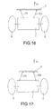
- Fig. 17 is a plan view showing another example of the arrangement of the front/rear link of this invention.
- Fig. 18 is a schematic rear view of the axle supporting structure for industrial vehicles showing yet another embodiment of this invention.
- Fig. 19 is a schematic rear view showing the operation state of the axle supporting structure for industrial vehicles shown in Fig. 18.
- Fig. 20 is a vector diagram showing the force acting on the control link of Fig. 18.
- FIG. 1 A first embodiment of this invention is hereafter described in Fig. 1 - Fig. 3.
- Fig. 1 is a rear view of a fork lift truck showing mainly the wheel axle and control link.
- Fig. 2 is a plan view of part of rear wheel axle and a control link.
- a rear wheel axle 1 (hereafter, axle) comprises a parallel upper member 2 and lower member 3 connected by a connection member 4.
- a swing shaft 5 is provided which extends in the front/rear direction of the vehicle. From the vehicle frame 6 whereof only a part is shown, a longitudinal slot 7 is formed in the left/right direction in a supporting member 6a which extends downwards, the swing shaft 5 being inserted in the slot 7 such that it is free to displace. The load of the body acts on the axle 1 through this swing shaft 5.
- the axle 1 can swing in the roll direction relative to the vehicle frame 6 around the swing shaft 5.
- the front wheel axle which supports the front wheels, not shown, is attached fixed to the vehicle frame. Therefore, the front wheel axle does not perform any swing motion relative to the vehicle frame.
- a steering knuckle 8 is supported via a king pin, not shown.
- the steering wheel 9 is supported by this steering knuckle 8.
- a steering linkage 10 which moves according to a steering operation from a steering handle, not shown, is connected with the steering knuckle 8, and the travelling direction of the vehicle is varied by freely changing the orientation of the steering wheel 9.
- the direction of the front wheels does not change, but the direction of the rear wheels changes to freely change the direction of travel.
- a control link 20 is attached to the upper surface of the axle 1 which connects the axle 1 to the vehicle frame 6.
- the control link 20 comprises a first link 25, second link 30 and third link 36.
- One end 22 (hereafter, connecting point) of the first link 25 is inserted in a slot 21 provided in the vehicle frame 6.
- the other end 24 (hereafter, also connecting point) of the first link 25 is inserted in the slot 23 provided horizontal with the upper surface of the upper member 2 of the axle 1.
- the first link 25 inclines, and the ends 22, 24 are arranged so that there is point symmetry across the center of the vehicle.
- the center section of the first link 25 is located in a vehicle center part, and an end 31 (hereafter, a connecting point) of the second link 30 is connected free to rotate via a pin, not shown.
- Another end 32 (hereafter, a connecting point) of the second link 30 is connected with an upper member 2 of the rear wheel axle 1 free to rotate via a pin, not shown.
- the connecting point 32 to the upper member 2 of the second link 30 and the connecting point 22 to the vehicle frame 6 of the first link 25 are arranged so that they are in the vicinity of same horizontal position.
- One end 37 (hereafter, an connecting point) of the third link 36 which extends horizontally connects with the other end 24 on the side of the axle 1 of the first aforesaid link 25 via a pin, not shown.
- the other end 35 (hereafter, a connecting point) of the third link 36 is connected free to rotate via a pin, not shown, relative to the supporting member 6a which is connected to the vehicle frame 6 located in the center of the vehicle.
- the connecting point 35 relative to the supporting member 6a of the third link 36 is situated immediately above the swing shaft 5.
- Fig. 2 is a view of the control link 20 from above.
- a hole 25a is provided in the center part of the first link 25, as shown here, and the end 31 of the second link 30 is inserted in this hole 25a, these elements being mutually connected by a pin, not shown, in this state.
- the third link 36 is formed of a pair of parallel links, the other end 24 of the first link 25 is inserted in the parallel links, and they are interconnected by a pin 36b at the connecting point37.
- the axle 1 is connected with the vehicle frame 6 via connecting links (connecting members) 11, 12 extending in the front/rear direction of the vehicle, as shown in Fig. 2.
- a swivel joint 13 is respectively arranged in each connecting part.
- the links 11, 12 are parallel to each other, are symmetrical to the left and right of the swing shaft 5 and are arranged at the same height as the swing shaft 5.
- an opening 2a is provided (Fig. 1, Fig. 2) in the upper member 2 of the axle 1.
- a block which can slide to the left and right may be provided on the side of the axle 1, and the first and third links 25, 36 joined to this block.
- the swing axis 5 rises, so the vehicle frame 6 also moves up.
- the connecting point 32 of the second link 30 separates from the connecting point 24 of the first, third links 25, 36. Consequently, the inclination of the first link 25 becomes less.
- the connecting point 22 of the first link 25 displaces to the right of the figure in the slot 21 in the horizontal direction, and the connecting point 24 displaces to the left of the figure in the slot 23.
- the upward motion amount of the connecting point 22 of the first link 25 and the upward motion amount of the swing axis 5 in the middle of the axle 1 due to the tilt of the axle 1, can be made approximately the same, and the vehicle body rises while remaining horizontal. In other words, a change in the posture of the vehicle is prevented.
- the connecting point 32 is kept at the same point, the first link 25 tends to raise , i.e., the inclination angle of the first link 25 increases, and the connecting point 22 of the first link 25 on the side of the vehicle frame 6 tends to be pushed upwards.
- outside tilt due to centrifugal force when the vehicle turns is suppressed, so stability of vehicle posture is improved.
- an optimum restoring moment can be obtained by suitably setting the inclination angle ⁇ of the first link 25 and the position n of the connecting point 22 of the first link 25 to the vehicle frame 6.
- the downward pulling force at this time may be treated in the same way as the force F which is an upward pushing force.
- the vehicle frame 6 is subject to an upward force from the first link 25, and if the left rear wheel 9 rides over a bump, the axle 1 swings in a clockwise and moves left side.
- the connecting point 22 of the first link 25 relative to the vehicle frame 6 moves to the left in the slot 21 and applies an upward force to the vehicle frame 6 at a new position.
- the above effects are particularly marked when the center of gravity is high, for example when the vehicle is handling a load in a high position.
- a further advantage is that sensors for detecting the slope of the road are not required.
- the swing axis 5 is supported on a block 14 provided free to slide in the slot 7 of the supporting member 6a.
- a low friction member 15 e.g. "OILES #2000" (Trademark of the OILES Co;) is disposed on the upper and lower surfaces of the block 14 which slides in slot 7 so as to reduce the sliding resistance, and the provision of a bush 16 between the swing axis 5 and block 14 also contributes to reducing the swing resistance of the axle 1.
- Figs. 5 and 6 are different from Figs. 1 to 4 in that the position of the control link 20 is lowered and part of it is located inside the axle 1.
- the axle 1 is connected to the vehicle frame 6 by the front/rear links 11, 12 in the same way as in Fig. 2.
- the front/rear position of the axle 1 and turning position around the yaw axis are restricted, and the vertical position of the axle 1 and turning position of the vehicle around the axis in the left/right directions are restricted by inserting the swing axis 5 of the axle 1 in the slot 7 of the vehicle frame 6 in the same way as in Fig. 1.
- the positional relationships of the first to third links 25, 30, 36 shown in Fig. 5 are identical to those of Fig. 1, and the connecting point 24 of the first link 25 to the axle 1 is connected so that it is free to displace horizontally relative to the connecting member 4 of the axle 1.
- a pin 36b which connects the first link 25 and third link 36 is disposed in a cylindrical part 4b fixed to the connecting member 4.
- Elastic (e.g., rubber) members 40 having holes 40a are inserted on both sides of the pin 36b in the cylindrical part 4b so as to allow movement of the pin 36b to the left and right.
- the connecting point 35 of the third link 36 is connected to the supporting member 6a connected to the vehicle frame 6.
- the third link 36 is formed of a pair of parallel links, the first link 25 being inserted between them, and these links are joined together by the pin 36b at the connecting point 24.
- the connecting point 32 of the second link 30 is connected to the connecting member 4 of the axle 1 so that it is free to rotate.
- a large opening 2b is provided in the upper member 2 of the axle 1 so as to allow accepting the first, second links 25, 30 and the end part of the supporting member 6a of the vehicle frame 6.
- the swing axis 5 of the axle 1 is supported free to move in a horizontal direction relative to the supporting member 6a part of the vehicle frame 6, as described above.
- the left and right movement of the connecting point 24 of the first, third links 25, 36 is performed while compressing the elastic members 40, so shocks and vibrations are absorbed, and the motion is smooth.
- Elastic members 40 for mitigating shocks having an identical construction to the above may be interposed at the connecting point 22 between the first link 25 and vehicle frame 6.
- a damper 50 such as shown in Fig. 7 can also be incorporated in the third link 36 or second link 30.
- the third link 36 is divided in the axial direction, one part comprising a cylinder 51 and the other part connected to a piston 52 sliding inside the cylinder 51, a spring (plate spring or the like) 53 is disposed on both sides of the piston 52, and contraction or extension is performed according to the impact in the axial direction acting on the third link 36.
- the contraction or extension stroke varies according to the magnitude of the impact load, and when the impact force disappears, the piston 52 is immediately pushed by the spring 53 back to the neutral position.
- the cylinder 51 When there is a vibration input which cannot be absorbed by the spring 53 alone, the cylinder 51 may be filled with a damping fluid 54 and a damping orifice 55 provided in the piston 52 to attenuate the vibration input.
- this shock can be absorbed by the extension/contraction of the second link 30 and third link 36 even if a shock such as a kickback acts to the left and right of the axle 1 from stones, etc, on the road surface. Therefore, damage of the first link 25 is prevented, and an upward pushing or downward pulling impact is prevented from acting on the vehicle frame 6 from the first link 25.
- damper mechanism which restricts the extension/contraction of the second link 30 and/or third link 36, the vibration of the first to third links 25, 30, 36 is suppressed, and vibration of the vehicle frame 6 or axle 1 connected to these links is also suppressed.
- the damper is not limited to this construction, and any damper known in the art may be employed.
- Fig. 8 The embodiment shown in Fig. 8 is a modification of the embodiment of Fig. 1.
- the first link 25 and vehicle frame 6 are connected by a perpendicular connecting link 41 joined by pins.
- control link 20 is identical to that of the example of Fig. 1, but as the connecting link 41 is used, sliding resistance between the vehicle frame 6 and first link 25 is eliminated, and the motion is made smooth.
- the site to which the connecting link 41 may be connected can also be applied to the connection between the connecting point 24 of the first, third links 25, 36 and the axle 1.
- shocks can be mitigated in the same way as in Fig. 4.
- the connecting link 41 may also be oriented in a downward direction from the connecting point 22 of the first link 25, and connected to the vehicle frame 6. This contributes to lowering the vehicle body.
- control link 20 is disposed with left and right reversed compared to the example shown in Fig. 1, the remaining features of the construction being identical to those of Fig. 1. In this example, the same effect is obtained as that of Fig. 1.
- control link 20 is disposed with top and bottom reversed compared to the example shown in Fig. 1.
- One end of the third link 36 is connected to the connecting point 22 of the first link 25, and the other end is connected to a supporting part 1a extending above the axle 1.
- the swing axis 5 is supported relative to the vehicle frame 6 in an identical way to that described above.
- Fig. 11 is a rear view showing a second embodiment of the invention wherein a bell crank is provided on the axle to convert the lateral displacement of the vehicle frame to a vertical displacement. This will be described assigning identical numerals to the same parts as those of Fig. 1.
- 60 is a bell crank provided free to rotate on a pin 60a on the axle 1.
- a horizontal arm 61 of the bell crank 60 is joined to the vehicle frame 6 via a vertical link 62, and a vertical arm 63 of the bell crank 60 is joined to an end of the supporting member 6a which extends downwards from the vehicle frame 6 via a horizontal link 64.
- An end 6b of the link 62 is connected free to slide in a long hole in the horizontal direction relative to the vehicle frame 6.
- the supporting member 6a extending downwards from the vehicle frame 6, projects downwards through a hole 2a provided in the upper frame 2 of the axle 1.
- the swing axis 5 of the axle 1 is inserted in the slot 11 in the lateral direction of the vehicle frame 6 in the same way as in Fig. 1, thereby restricting the vertical position and turning position of the axle 1 around the left or right axis, and front/rear motion and turning in the yaw direction of the axle 1 is restricted by the front/rear link, as in Fig. 1.
- the aforesaid elastic member may also be disposed at the connecting point 6b of the link 62 and vehicle frame 6 so as to absorb vibrations and shocks.
- the vertical arm 63 extending upwards from the pivot point of the bell crank 60 and connected to the vehicle frame 6 by the horizontal link 64, and the horizontal arm 61 extending horizontally from the pivot point 60a and connected to the vehicle frame 6 by the vertical link 62, are provided.
- Fig. 13 the only difference from Fig. 12 is that the part of the vehicle frame 6 situated in the lateral direction and the vertical arm 63 of the bell crank 60 provided on the axle 1 are connected by the horizontal link 64, the remaining features being identical to those of Fig. 12.
- the bell crank 60 was disposed on the side of the axle 1, but the invention is not limited to this example.
- the bell crank 60 may also be disposed free to swing in the vehicle frame 6, the vertical link and horizontal link being interposed with the axle 1 whereupon an identical effect is obtained.
- the vehicle frame 6 is free to displace to the left and right relative to the axle 1, the left/right displacement of the vehicle frame 6 is detected by the horizontal link 64 acting as a detecting member, and the bell crank 60 and vertical link 62 which are working members apply a force tending to tilt the vehicle frame 6 to the rear of the displacement direction.
- the horizontal link 64 acting as a detecting member
- the bell crank 60 and vertical link 62 which are working members apply a force tending to tilt the vehicle frame 6 to the rear of the displacement direction.
- the horizontal link 64 which is a detecting member, detects the displacement of the vehicle frame 6 on the downward slope relative to the axle 1, and the bell crank 60 and vertical link 62 which are working members cause the vehicle frame 6 to tilt towards the rear of the displacement direction, so the tilt of the vehicle down the slope is suppressed and the vehicle posture is stabilised which also give the operator a sense of stability and relief.
- a vertical load is supported on the axle 1 via the swing axis 5 from the vehicle frame 6, so the load acting on the horizontal link 64, vertical link 62 and bell crank 60 can be reduced, and as these elements do not have to be made rigid, costs can be made more economical.
- Fig. 15 shows a third embodiment of this invention.
- a guide surface 70 is provided whereof, as one of the axle 1 and vehicle frame 6 (in this example, the axle 1) moves away from the center of the vehicle, the other approaches it, and two elastic members 71a, 71b are provided which slide on this guide surface 70 on the other of the two elements (in this example, the vehicle frame 6).
- the guide surface 70 provided on the upper surface of the axle 1 comprises inclined surfaces 70a, 70b which are symmetrical about the swing axis 5.
- the elastic members 71a, 71b comprise a spherical member 73 guided by a cylindrical member 72 fixed perpendicular to the vehicle frame 6, and a spring 74 which pushes the spherical member 73 towards the rear surface.
- the spherical member 73 is allowed to move so that it does not interfere even if the guide surface 70 approaches.
- the axle 1 is connected to the vehicle frame 6 by the front/rear links 11, 12 as in Fig. 2, thereby restricting the front/rear position and turning position around the yaw axis of the axle 1.
- the vertical position and turning position of the axle 1 around the left and right axis are restricted by inserting the swing axis 5 of the axle 1 in the slot 7 in the lateral direction of the vehicle frame 6, as in Fig. 1.
- the left-hand elastic member 71b rides over the sloping surface 70b, so the tilt of the vehicle to the left is suppressed by the upward pushing force of the left-hand elastic member 71b.
- the vehicle wheels 9 ride over bumps and the vehicle travels on a road surface with imperfections
- the axle 1 displaces due to the force component in the axle direction generated according to the tilt of the axle 1
- the positions of the elastic members 71a, 71b change relative to the guide surface 70, and the posture is adjusted so that the tilt of the vehicle is suppressed as described above.
- the characteristics of vehicle posture control may also be varied by increasing the tilt angle of the guide surface 70.
- Fig. 16 shows an embodiment wherein the front/rear links connect the axle 1 to the vehicle frame 6.
- this yawing moment of the axle 1 is in an anticlockwise direction, and if the vehicle turns to the right, it is in a clockwise direction.
- the wheel 9 on the steering side may be rotated inside the turn, so the vehicle can be understeered, and forward stability of the vehicle is improved.
- This disposition of the front/rear links 11a, 12a may be applied to any of the embodiments shown in Fig. 1 to Fig. 15.
- Fig. 17 shows a different layout from the layout shown in Fig. 16.
- the interval between the connecting points of the former to the vehicle frame 6 is less than the interval between the connecting points to the axle 1.
- the vehicle frame 6 can be displaced outside based on the turn, a compressing force acts on the front/rear link on the outside of the turn, a pulling force acts on the front/rear link on the inside of the turn, and a moment around the yaw axis opposite to that of Fig. 16 is supplied to the axle 1 in a horizontal plane.
- this yawing moment of the axle 1 is in a clockwise direction, and if the vehicle turns to the right, it is in an anticlockwise direction.
- the wheel 9 on the steering side can be rotated outside the turn, so the vehicle can be understeered, and the turning characteristics and small radius turning of the vehicle are improved.
- Fig. 18-Fig. 20 show a fourth embodiment of this invention.
- axle 1 and vehicle frame 6 are joined by two links disposed in a trapezoid arrangement. Identical numerals are assigned to the same parts as those of Fig. 1.
- the vehicle frame 6 and axle 1 are connected by a pair of left/right links 81, 82 disposed in a vertical direction, the connecting points being free to rotate.
- the links 81, 82 are disposed symmetrically to the left and right of the vehicle center, and fixed so that they are inclined to one another on mutually opposite sides.
- these links 81, 82 are flat links having a longer width in the front/rear direction, or are four links arranged in pairs in the front/rear direction.
- the swing axis 5 of the axle 1 of the aforesaid embodiments is omitted, and the vehicle frame 6 is supported on the axle 1 only by the left/right links 81, 82.
- the left/right links 81, 82 rising from the rear wheel axle 1 can be supported on the rear wheel axle 1 symmetrically inclined towards the center of the vehicle.
- the left-hand link 82 ascends, so the left-hand side of the vehicle frame is pushed up and the tilt of the vehicle body towards left is prevented.
- a centrifugal force acts in the direction of the arrow F
- the horizontal force due to the centrifugal force is F
- the point of action of this horizontal force F is the centre of gravity of the vehicle.
- the distance between the virtual rotation center where the center parts of the vehicle on the extrapolations of the left/right links 81, 82 intersect, and the ends of the left/right links 81, 82 is HO
- the distance between the center of gravity and the ends of the left/right links 81, 82 is H
- the interval between the connecting points of the left/right links 81, 82 to the vehicle frame 6 is L1 .
- Theta is the angle subtended by the links 81, 82 with the horizontal plane.
- Horizontal forces (F/2) act respectively on the connecting points of the left/right links 81, 82 with the vehicle frame 6. Due to these horizontal forces, in the left-hand link 82, a force (1/2) F ⁇ tan ⁇ is produced which pulls the vehicle frame 6 downwards. In the right-hand link 81, a force (1/2) F ⁇ tan ⁇ is produced which pushes the vehicle frame 6 upwards.
- H0 (1/2)tan theta x L1
- M1 F x H0 (anticlockwise).
- left/right characteristics are symmetrical, and high compatibility with the layout of the vehicle frame 6 and axle 1 of a fork lift truck can be achieved by a simple construction.
- the left/right links 81, 82 were disposed with the axle 1 downwards and the vehicle frame 6 upwards, but part of the vehicle frame 6 may be disposed in the part below the axle 1, and the vehicle frame 6 suspended below the axle 1.
- the positional relationships of the left/right links 81, 82 is the same, and an identical effect to that of the above example is obtained by making the interval L2 between the connecting points on the axle 1 side less than the interval L1 between the connecting points on the vehicle frame 6 side.
Landscapes
- Engineering & Computer Science (AREA)
- Mechanical Engineering (AREA)
- Vehicle Body Suspensions (AREA)
- Forklifts And Lifting Vehicles (AREA)
Abstract
Description
The
Claims (15)
- An axle supporting structure for industrial vehicles, comprising:an axle(1) supporting wheels(9), the axle(1) being supported free to swing in its center part relative to the vehicle frame(6) and free to displace in the left and right directions,a first link(25), one end(24) of the first link(25) being connected to the axle(1) so that it is free to displace in the left and right directions of the vehicle, the other end being connected to the vehicle frame(6) so that it is free to displace in the left and right directions of the vehicle, and the link(25) being inclined,a second link(30), one end(31) of the second link(30) being connected to the vicinity of the middle point of the first link(25), the other end(32) being connected to one of the axle(1) and vehicle frame(6), and the link(30) being inclined, anda third link(36), one end(37) of the third link(36) being connected to the other end(24) of the first link(25), its other end(36) being connected to one of the vehicle frame(6) and the axle(1), and the link(36) being disposed substantially parallel to the axle(1), wherein:the inclination angle of the first link(25) varies according to the relative positions of the axle(1) and vehicle frame(6) to the left and right of the vehicle, and the vehicle posture is thereby controlled.
- An axle supporting structure for industrial vehicles as defined in Claim 1, wherein a swing axis(5) which extends in the front and rear directions of the vehicle is provided on the axle(1), and the swing axis(5) is inserted into a slot(7) extending in the left and right directions of the vehicle body provided in the vehicle frame(6).
- An axle supporting structure for industrial vehicles as defined in Claim 1, wherein the other end(32) of the second link(30) connected to the first link(25) is connected to the axle(1), the other end(35) of the third link(36) connected to the first link(25) is connected to the vehicle frame(6), and the swing center of the axle(1) is disposed lower than the connecting sites of the first link(25) and second link(30) to the axle(1).
- An axle supporting structure for industrial vehicles as defined in Claim 1, wherein the second link(30) or third link(36) extends and contracts in the axial direction.
- An axle supporting structure for industrial vehicles as defined in Claim 1, wherein the second link(30) or third link(36) comprises a damper(50) mechanism which restricts the extension and contraction.
- , An axle supporting structure for industrial vehicles as defined in Claim 1, wherein a connecting part between the upper end(22) of the first link(25) and the vehicle frame(6) or connecting part between the lower end(24) and the axle(1) is connected via an elastic member(40) which permits displacement in the left and right directions.
- An axle supporting structure for industrial vehicles as defined in Claim 1, wherein a connecting part between the upper end(22) of the first link(25) and the vehicle frame(6) or a connecting part between the lower end(249 of the first link(25) and the axle(1) is connected to the vehicle frame(6) or the axle(1) via a vertical link(41) provided free to swing on the axle(1) or the vehicle frame(6).
- An axle supporting structure for industrial vehicles as defined in Claim 1, wherein the other end(32) of the second link(30) connected to the first link(25), is connected to the vehicle frame(6), and the other end of the third link(36) connected to the first link(25), is connected to a supporting member(1a) formed in one piece with the axle(1).
- An axle supporting structure for industrial vehicles, comprising:an axle(1) supporting wheels(9), the axle(1) being supported free to swing in its middle part relative to the vehicle frame(6), and free to displace in the left and right directions,a detecting member, this detecting member detecting the relative displacement of the vehicle frame(6) and axle(1) in the left and right directions, anda working member, the working member being connected to the axle(1) and the vehicle frame(6), and supplying a force which tilts the vehicle frame(6) according to the action of the detecting member, wherein:the working member displaces via the detecting member according to the relative displacement of the axle(1) and the vehicle frame(6) in the left and right directions of the vehicle, and the posture of the vehicle is thereby controlled.
- An axle supporting structure for industrial vehicles as defined in Claim 9, wherein:the working member is a bell crank(60) disposed free to swing on the axle(1) or vehicle frame(6), the crank connecting the vehicle frame(6) or axle(1) and a horizontal arm(61) by a vertical link(62), andthe detecting member is a horizontal link(64) which connects the vertical arm(63) of the of bell crank(60), and the vehicle frame(6) or axle(1).
- An axle supporting structure for industrial vehicles, comprising:an axle(1) supporting wheels(9), the axle(1) being supported free to swing in its center part relative to the vehicle frame(6) and free to displace in the left and right directions,a guide member(70), the guide member(70) being disposed in one of the axle(1) and vehicle frame(6), and comprising a pair of guide surfaces(70a,70b) incline so as to approach the other of these with increasing distance from the center of the vehicle, anda pair of the elastic members(71a,71b), the elastic members(71a,71b) being disposed in one of the vehicle frame(6) and axle(1), and sliding on the pair of guide surfaces(70a,70b), wherein:the elastic members(71a,71b) displace along the guide surfaces(70a,70b) according to the relative displacement of the axle(1) and vehicle frame(6) to the left and right directions of the vehicle, and thereby control the posture of the vehicle.
- An axle supporting structure for industrial vehicles as defined in any of Claims 1, 9 or 11, wherein the axle(1) is connected to the vehicle frame(6) by a pair of front and rear links(11,12) extending in the front and rear direction of the vehicle in the same horizontal plane.
- An axle supporting structure for industrial vehicles as defined in Claim 12, wherein the pair of front and rear links( 11,12) are mutually parallel.
- An axle supporting structure for industrial vehicles as defined in Claim 12, wherein, in the pair of front and rear links(11,12), the interval between the connecting points to the vehicle frame(6) is different from the interval between the connecting points to the axle(1).
- An axle supporting structure for industrial vehicles, comprising:an axle(1) supporting wheels(9),a vehicle frame(6), anda pair of links(81,82) which connect the axle(1) and the vehicle frame(6), these links(81,82) being disposed symmetrically about the center of the vehicle and inclining symmetrically with respect to each other, wherein:the pair of links(81,82) incline differently according to the relative displacement of the axle(1) and vehicle frame(6) in the left and right directions of the vehicle, and the posture of the vehicle is thereby controlled.
Applications Claiming Priority (4)
| Application Number | Priority Date | Filing Date | Title |
|---|---|---|---|
| JP2000321287 | 2000-10-20 | ||
| JP2000321287 | 2000-10-20 | ||
| JP2000373879A JP3747776B2 (en) | 2000-10-20 | 2000-12-08 | Axle support structure for industrial vehicles |
| JP2000373879 | 2000-12-08 |
Publications (2)
| Publication Number | Publication Date |
|---|---|
| EP1199195A2 true EP1199195A2 (en) | 2002-04-24 |
| EP1199195A3 EP1199195A3 (en) | 2004-02-04 |
Family
ID=26602517
Family Applications (1)
| Application Number | Title | Priority Date | Filing Date |
|---|---|---|---|
| EP01123503A Withdrawn EP1199195A3 (en) | 2000-10-20 | 2001-09-28 | Axle linkage for industrial vehicle |
Country Status (3)
| Country | Link |
|---|---|
| US (1) | US20020047303A1 (en) |
| EP (1) | EP1199195A3 (en) |
| JP (1) | JP3747776B2 (en) |
Cited By (2)
| Publication number | Priority date | Publication date | Assignee | Title |
|---|---|---|---|---|
| DE102005056835B3 (en) * | 2005-10-19 | 2007-06-21 | Kia Motors Corporation | Side coupling device for vehicle suspension devices |
| EP1997654A3 (en) * | 2007-05-31 | 2009-09-30 | CLAAS Selbstfahrende Erntemaschinen GmbH | Vehicle with an axle with pivoting movement |
Families Citing this family (6)
| Publication number | Priority date | Publication date | Assignee | Title |
|---|---|---|---|---|
| US10427483B1 (en) | 2013-04-10 | 2019-10-01 | Ala Holdings, Llc | Adjustable ride height, vehicle, system and kit |
| US9150247B2 (en) * | 2013-04-10 | 2015-10-06 | Aaron L. Aldrich | Adjustable ride height, vehicle, system and kit |
| US10099530B2 (en) * | 2016-08-23 | 2018-10-16 | Matthew Ethan Grimes | Vehicle suspension pan hard bar (track bar) tensioning and damping technique |
| US10639952B2 (en) * | 2017-12-01 | 2020-05-05 | Mahindra N.A. Tech Center | Vehicle suspension |
| US11135887B2 (en) | 2018-10-19 | 2021-10-05 | Ala Holdings, Llc | Adjustable suspension mount system and method |
| EP4134256A1 (en) * | 2021-08-10 | 2023-02-15 | Agco Corporation | Vehicle having a laterally adjustable chassis and methods of servicing such a vehicle |
Family Cites Families (12)
| Publication number | Priority date | Publication date | Assignee | Title |
|---|---|---|---|---|
| US1127608A (en) * | 1914-04-13 | 1915-02-09 | Archibald Bruce Ferguson | Spring suspension. |
| US2092676A (en) * | 1934-10-15 | 1937-09-07 | Kolbe Joachim | Motor vehicle |
| US2094174A (en) * | 1934-11-16 | 1937-09-28 | Bertram J Grigsby | Spring mounting of vehicle bodies |
| US2623758A (en) * | 1949-09-15 | 1952-12-30 | Cruz Rogelio Gonzalez | Stabilizer device for automobiles, trucks, and the like |
| FR1013365A (en) * | 1950-02-28 | 1952-07-28 | Suspension device for vehicles | |
| US2770468A (en) * | 1954-01-25 | 1956-11-13 | Elijah N Willingham | Vehicle sway stabilizer |
| JPS58118446A (en) * | 1982-01-06 | 1983-07-14 | 株式会社日立製作所 | Body tilting device |
| US4802689A (en) * | 1984-07-31 | 1989-02-07 | Daimler-Benz Aktiengesellschaft | Suspension system for rigid vehicle axle |
| JP3230245B2 (en) * | 1991-03-29 | 2001-11-19 | 日産自動車株式会社 | Axle beam suspension for vehicles |
| US6179328B1 (en) * | 1997-04-14 | 2001-01-30 | Nissan Motor Co., Ltd. | Vehicle rear suspension apparatus |
| US6517094B1 (en) * | 2000-03-30 | 2003-02-11 | American Axle & Manufacturing, Inc. | Hydraulic anti-roll suspension system for motor vehicles |
| US6357768B1 (en) * | 2000-09-19 | 2002-03-19 | General Motors Corporation | Straight line linkage mechanism |
-
2000
- 2000-12-08 JP JP2000373879A patent/JP3747776B2/en not_active Expired - Fee Related
-
2001
- 2001-09-28 EP EP01123503A patent/EP1199195A3/en not_active Withdrawn
- 2001-10-16 US US09/977,405 patent/US20020047303A1/en not_active Abandoned
Cited By (3)
| Publication number | Priority date | Publication date | Assignee | Title |
|---|---|---|---|---|
| DE102005056835B3 (en) * | 2005-10-19 | 2007-06-21 | Kia Motors Corporation | Side coupling device for vehicle suspension devices |
| US7390000B2 (en) | 2005-10-19 | 2008-06-24 | Kia Motors Corporation | Lateral link for vehicle suspension systems |
| EP1997654A3 (en) * | 2007-05-31 | 2009-09-30 | CLAAS Selbstfahrende Erntemaschinen GmbH | Vehicle with an axle with pivoting movement |
Also Published As
| Publication number | Publication date |
|---|---|
| EP1199195A3 (en) | 2004-02-04 |
| JP3747776B2 (en) | 2006-02-22 |
| JP2002192926A (en) | 2002-07-10 |
| US20020047303A1 (en) | 2002-04-25 |
Similar Documents
| Publication | Publication Date | Title |
|---|---|---|
| US5839741A (en) | Suspension with interconnected torsion bars | |
| JP3370662B2 (en) | Suspension device for vehicles | |
| JPWO1993004881A1 (en) | Suspension system for work vehicles | |
| US20180334001A1 (en) | Suspension device for non-steered driving wheel incorporating in-wheel motor | |
| KR20230086031A (en) | Independent Corner Module | |
| CN113386874B (en) | Three-row wheel vehicle | |
| KR20100016064A (en) | Roll-stabilizing fifth wheel apparatus | |
| EP1199195A2 (en) | Axle linkage for industrial vehicle | |
| JP4243432B2 (en) | Bogie structure | |
| CN110722946B (en) | Vehicle posture active adjustment system and vehicle | |
| KR100521217B1 (en) | front suspension structure of vehicle | |
| JP2004505842A (en) | Configuration of vehicle wheel suspension | |
| KR102895428B1 (en) | Independent Suspension System | |
| KR20040055736A (en) | Method and apparatus for suspending a vehicular wheel assembly | |
| KR20060110381A (en) | Car suspension | |
| KR102240958B1 (en) | Vehicle lower arm control apparatus for driving stability and soft ride comfort | |
| JPH04129812A (en) | Rear suspension for vehicle | |
| JPH06211014A (en) | Steering wheel suspension | |
| JP2018020623A (en) | Tricycle | |
| JP2020203629A (en) | Lean type vehicle and vehicular lean unit | |
| KR100699485B1 (en) | Active Geometry Control Suspension System | |
| KR100579734B1 (en) | Link structure of automobile suspension | |
| JPH06278427A (en) | Vehicular rear suspension device | |
| KR100527769B1 (en) | suspension system of vehicle | |
| KR100276704B1 (en) | Understeer improvement device of automobile |
Legal Events
| Date | Code | Title | Description |
|---|---|---|---|
| PUAI | Public reference made under article 153(3) epc to a published international application that has entered the european phase |
Free format text: ORIGINAL CODE: 0009012 |
|
| 17P | Request for examination filed |
Effective date: 20010928 |
|
| AK | Designated contracting states |
Kind code of ref document: A2 Designated state(s): AT BE CH CY DE DK ES FI FR GB GR IE IT LI LU MC NL PT SE TR |
|
| AX | Request for extension of the european patent |
Free format text: AL;LT;LV;MK;RO;SI |
|
| RIN1 | Information on inventor provided before grant (corrected) |
Inventor name: OKANO, KIMIHIKO Inventor name: HOSOTANI, TAKASHI |
|
| PUAL | Search report despatched |
Free format text: ORIGINAL CODE: 0009013 |
|
| AK | Designated contracting states |
Kind code of ref document: A3 Designated state(s): AT BE CH CY DE DK ES FI FR GB GR IE IT LI LU MC NL PT SE TR |
|
| AX | Request for extension of the european patent |
Extension state: AL LT LV MK RO SI |
|
| RIC1 | Information provided on ipc code assigned before grant |
Ipc: 7B 60G 9/02 B Ipc: 7B 60G 9/00 A |
|
| AKX | Designation fees paid |
Designated state(s): DE FR GB |
|
| STAA | Information on the status of an ep patent application or granted ep patent |
Free format text: STATUS: THE APPLICATION HAS BEEN WITHDRAWN |
|
| 18W | Application withdrawn |
Effective date: 20060323 |