EP1198397B1 - Systeme de manipulation de medicaments utilise pour charger des chariots a medicaments - Google Patents
Systeme de manipulation de medicaments utilise pour charger des chariots a medicaments Download PDFInfo
- Publication number
- EP1198397B1 EP1198397B1 EP00939569A EP00939569A EP1198397B1 EP 1198397 B1 EP1198397 B1 EP 1198397B1 EP 00939569 A EP00939569 A EP 00939569A EP 00939569 A EP00939569 A EP 00939569A EP 1198397 B1 EP1198397 B1 EP 1198397B1
- Authority
- EP
- European Patent Office
- Prior art keywords
- medications
- medication
- assembly
- loading assembly
- cart
- Prior art date
- Legal status (The legal status is an assumption and is not a legal conclusion. Google has not performed a legal analysis and makes no representation as to the accuracy of the status listed.)
- Expired - Lifetime
Links
- 229940079593 drug Drugs 0.000 title claims abstract description 242
- 239000003814 drug Substances 0.000 title claims abstract description 242
- 238000002483 medication Methods 0.000 claims abstract description 123
- 230000000153 supplemental effect Effects 0.000 claims abstract description 37
- 238000003860 storage Methods 0.000 claims abstract description 31
- 230000000712 assembly Effects 0.000 claims abstract description 16
- 238000000429 assembly Methods 0.000 claims abstract description 16
- 230000005484 gravity Effects 0.000 claims abstract description 9
- 230000010006 flight Effects 0.000 claims description 3
- 230000003247 decreasing effect Effects 0.000 claims 1
- 230000009471 action Effects 0.000 abstract description 4
- 230000032258 transport Effects 0.000 description 26
- 230000033001 locomotion Effects 0.000 description 6
- 239000000969 carrier Substances 0.000 description 4
- 230000036541 health Effects 0.000 description 4
- 230000007246 mechanism Effects 0.000 description 4
- 230000008901 benefit Effects 0.000 description 3
- 238000000034 method Methods 0.000 description 3
- 238000004806 packaging method and process Methods 0.000 description 3
- 230000008569 process Effects 0.000 description 3
- 229910001220 stainless steel Inorganic materials 0.000 description 3
- 239000010935 stainless steel Substances 0.000 description 3
- 230000005355 Hall effect Effects 0.000 description 1
- 241001417527 Pempheridae Species 0.000 description 1
- 235000014676 Phragmites communis Nutrition 0.000 description 1
- 230000000694 effects Effects 0.000 description 1
- 230000003203 everyday effect Effects 0.000 description 1
- 238000005429 filling process Methods 0.000 description 1
- 230000006870 function Effects 0.000 description 1
- 230000006872 improvement Effects 0.000 description 1
- 238000005304 joining Methods 0.000 description 1
- 210000004072 lung Anatomy 0.000 description 1
- 238000004519 manufacturing process Methods 0.000 description 1
- 230000004048 modification Effects 0.000 description 1
- 238000012986 modification Methods 0.000 description 1
- 230000000474 nursing effect Effects 0.000 description 1
- 230000002093 peripheral effect Effects 0.000 description 1
- 230000009467 reduction Effects 0.000 description 1
- 239000007858 starting material Substances 0.000 description 1
- 238000006467 substitution reaction Methods 0.000 description 1
Images


Classifications
-
- A—HUMAN NECESSITIES
- A61—MEDICAL OR VETERINARY SCIENCE; HYGIENE
- A61J—CONTAINERS SPECIALLY ADAPTED FOR MEDICAL OR PHARMACEUTICAL PURPOSES; DEVICES OR METHODS SPECIALLY ADAPTED FOR BRINGING PHARMACEUTICAL PRODUCTS INTO PARTICULAR PHYSICAL OR ADMINISTERING FORMS; DEVICES FOR ADMINISTERING FOOD OR MEDICINES ORALLY; BABY COMFORTERS; DEVICES FOR RECEIVING SPITTLE
- A61J7/00—Devices for administering medicines orally, e.g. spoons; Pill counting devices; Arrangements for time indication or reminder for taking medicine
- A61J7/0076—Medicament distribution means
- A61J7/0084—Medicament distribution means for multiple medicaments
-
- A—HUMAN NECESSITIES
- A61—MEDICAL OR VETERINARY SCIENCE; HYGIENE
- A61G—TRANSPORT, PERSONAL CONVEYANCES, OR ACCOMMODATION SPECIALLY ADAPTED FOR PATIENTS OR DISABLED PERSONS; OPERATING TABLES OR CHAIRS; CHAIRS FOR DENTISTRY; FUNERAL DEVICES
- A61G12/00—Accommodation for nursing, e.g. in hospitals, not covered by groups A61G1/00 - A61G11/00, e.g. trolleys for transport of medicaments or food; Prescription lists
- A61G12/001—Trolleys for transport of medicaments, food, linen, nursing supplies
Definitions
- This invention relates generally to automatic medication-dispensing systems for use in health care facilities such as hospitals, and more specifically concerns a system for transporting and loading previously dispensed medications into patient bins in a medication cart.
- Providing correct medications in a timely manner to patients is an important, if not vital, function of health care facilities, such as hospitals and nursing homes.
- the prescribed medications are picked (collected) by hand in a central pharmacy and distributed to the patients in the facility at specified times during the day. Delivery of medications to the patients is accomplished in various ways.
- medications are provided to patients individually, while in other cases, medications for all patients in a particular location, such as a hospital ward, are delivered and administered from a single medication cart, which holds the medications for individual patients in separate bins or drawers in the cart.
- Such conventional dispensing and delivery systems are quite time-consuming and prone to errors. In particular, a substantial amount of professional time is inefficiently used in the filling and delivery of medications with such systems.
- the medication cart itself is often the focus of attention, with various arrangements, such as shown in U.S. Patents No. 3,310,199 to Roberts et al , 5,011,240 to Kelley et al and 5,314,243 to McDonald et al , some of which include a plurality of patient-specific compartments.
- Some of these carts attempt to uniquely address individual drawers, which are assigned on a patient-by-patient basis, with various access protection arrangements.
- Such medication carts have had varying acceptance, although they still must typically be hand-loaded from a medication dispensing location, usually a central pharmacy, or in some cases, depending upon the particular facility, various satellite pharmacy stations which are in turn serviced by a central pharmacy.
- prescribed medications for individual patients are dispensed automatically on demand from a central dispensing apparatus which includes storage capability for a large number of medications.
- Many of these systems include software control features linking a hospital computer which has the medication records for all of the facility's patients.
- One such system is shown in U.S. Patent No. 4,546,901 to Butarazi , while other such systems are shown in U.S. Patents No. 4,655,026 to Wigoda , 4,785,969 to McLaughlin and 4,487,764 to Halvorson .
- Such systems while alleging improvement in filling time and error reduction, are often not commercially viable because of manufacturing expense and lack of operational reliability. Even the commercial systems are still subject to errors and are typically not fast enough to adequately service large facilities, in which medications must be provided to a large number of patients at least three times each day.
- US-A-655026 describes a system for packaging loose medication and for printing out details of the medication onto the packaging.
- US-A-5988858 describes a feed line at a first end of which a carrier feed unit deposits empty carriers.
- the carriers are moved along the feed line and medication is deposited into the carriers by processing units.
- a carrier receiving unit removes the carriers.
- the processing unite are controlled by a control unit.
- US-A-5348061 describes a system that stages orders of medications (e.g. tablets) in advance of a vial-filling process in an attempt to increase the speed of the vial filling processing whilat maintaining tablet count accuracy.
- medications e.g. tablets
- US 5875883 describes a conveyor with an adjustable inclined portion.
- DE 3742728 describes an apparatus for disentangling lung bolt-shaped parts, at one end of which a sorting device comprising spaced rollers may be arranged.
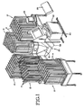
- Figure 1 shows an automatic medication dispensing and delivery system which includes the medication handling system of one embodiment of the present invention.
- the medication handling system disclosed herein receives medications which are automatically provided from a plurality of medication storage assemblies or vaults and then transports and loads those medications into, for instance, patient or medication bins in a medication cart which can in turn be transported directly to a hospital ward, where the medications are administered to the patients.
- the system can also be used to load medications into other open containers, including various bin styles and envelopes.
- the automatic medication system 10, shown in Figure 1 includes five separate medication storage assemblies or vaults 12-12.
- each storage assembly includes a large number of individual medication storage cartridges 14-14, with each storage cartridge containing only one type of medication.
- Each medication in the cartridge is typically enclosed within a uniform-size package.
- Each of the storage cartridges 14 includes a delivery control mechanism at a lower end thereof which is automatically controlled to release a single package from the cartridge upon a signal command. The released packages fall into a trough member located below each medication vault, and are then moved by a sweeper element to a central loading assembly.
- dispensing system described above is only one example of an automatic medication dispensing system and does not form a part of the present invention. Various arrangements of medication dispensing systems may be used.
- the dispensing system typically will contain various drugs, as well as other useful medical supplies, such as syringes, etc.
- the term "medications" used hereinafter is intended to include both medications per se, i.e. drugs, as well as medical supplies, such as syringes, etc.
- the medications are dispensed to a medication transport and loading assembly, referred to generally at 20, which then moves the medications to and loads the medications into a medication receptacle, which in one example is a medication bin in a medication cart, shown generally at 22.
- a medication receptacle which in one example is a medication bin in a medication cart, shown generally at 22.
- Various "open top" containers could be used with the system of the present invention, however, including various bin configurations in different cart arrangements and various envelope configurations.
- the entire assembly 20 is hereinafter referred to as a medication handling system or medication loading system.
- the system is under the control of a computer 23 and appropriate control software therein.
- the loading assembly 20 transports successive groups of selected medications, each group for a single patient or in some cases a single unit-of-use medication, such as a starter dose, and loads them into selected bins or portions thereof present in cart 22.
- Cart 22 will typically include a plurality of individual medication bins which are adapted to receive the individual groups of medications.
- the bins are elongated members which are semi-cylindrical in cross-section and which extend for the length of the cart.
- the bins are supported to move within the cart under software control. When a selected bin is at the top of the cart, it is exposed by opening doors or the like in the top of the cart immediately above the selected bin.
- the medications can then be conveniently removed from the cart by a nurse or other person administering the medications.
- the movement of the bins within the cart is controlled so that each bin can be individually brought to the loading/unloading position.
- each medication bin is divided into a plurality of equal length sectors.
- each medication bin has a total of nine such sectors.
- a divider may be positioned between adjacent sectors, so as to physically separate the successive sectors. Two or more individual adjacent sectors can together form a larger portion of the bin.
- the term "cell" is used herein to refer to one or more sectors, defined by dividers, depending upon the size needed for a particular patient. Cells can be assigned to individual patients or individual medications.
- the loading systems is capable of moving selected medications into selected cells.
- the location of each cell (the correct bin and location within the bin) associated with each patient (for patient-specific bins) is maintained in memory in the control portion 23 of the overall system.
- supplemental medications are provided by a supplemental doses assembly 26.
- These supplemental medications are available typically in the central pharmacy from which the storage assemblies themselves are periodically filled. They are not prescribed sufficiently often, however, to warrant a separate storage cartridge of their own in the automatic dispensing system. When needed, these medications are hand-picked from the stores in the central pharmacy and loaded into supplemental doses assembly 26.
- the supplemental doses assembly 26 fits onto the front end of the loading assembly 20, close to the funnel-like portion 58 leading to the bins in the cart.
- Figure 1 shows it exploded away from the funnel portion.
- the supplemental doses assembly 26, which will be described in more detail below, includes a tray-like arrangement of compartments, each of which has an independently controlled access door. When a particular medication cart 22 is to be filled by the automatic system shown in Figure 1 , any medications not present in the storage vaults will be provided by the supplemental doses assembly 26.
- the supplemental doses assembly 26 is controlled so that as a particular patient's dispensed medications are transported to the bin filling portion of the present system, the appropriate compartments on the supplemental doses assembly containing the prescribed additional medications for that patient are opened, releasing those medications into the bin filling portion of the system, joining with the medications dispensed from the storage vaults.
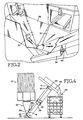
- FIGS 1-4 show a receiving assembly portion 30 of the loading system 20.
- the receiving portion 30 includes a series of trough-like funnels 32, which extend from the ends of the medication troughs beneath each of the vaults, and deflectors 33 which join adjacent funnels 32, all sloping downwardly and leading to a collector member 34 which is a short, square section, approximately 200mm (8 inches) square, through which the medications dispensed from the storage vaults fall, by gravity action.
- the various portions of the deceiving assembly can be altered in configuration and arrangement to accommodate the particular arrangement of the storage vaults being used.
- the medications upon being swept out of the medication troughs beneath the storage vaults, simply continue to move/fall by gravity action along the funnel/deflector assembly and then through the collector member 34 into the lower end 39 of a transport tube 38.
- Transport tube 38 has an opening 41 in its upper surface near a lower end 39 of the tube. Opening 41 is in registry with and is approximately the same size or slightly larger than the collector member 34 immediately above it. Transport tube 38 is so arranged that the medications, upon being moved from the medication vault troughs, simply fall into tube 38 without being caught or hung up on the funnel/deflector assembly.
- transport tube 38 is 228mm (9 inches) square by 1830mm (72 inches) long and is made from stainless steel.
- Lower end 39 of transport tube 38 is typically positioned either on the ground or a short distance above the ground.
- transport tube 38 extends at an angle of approximately 45° away from the medication vaults. The angle could typically be in the range of 35°-55°.
- rear end 39 of transport tube 38 is approximately 610mmn (24 inches) below the bottom of the medication troughs beneath each vault. If the medication assemblies are sufficiently elevated, however, the transport tube need not be inclined.
- plunger 42 Positioned within transport tube 38 is a stainless Steel plunger 42.
- plunger 42 is 222 mm (8.75 inches) square, so that there is approximately 3mm (1/8 inch) clearance between the peripheral edge of the plunger and the internal surface of the transport tube.
- An air cylinder 44 moves the plunger within transport tube 38 under computer control. When the prescribed medications for a particular patient are received through opening 41, plunger 42 is at the lower end 39 of the tube. When all the medications of a patient are in the tube, air cylinder 44 is activated, moving the plunger up the length of the transport tube, passing several spaced sensors in its trip. A total of four sensors 48, 49, 50 and 51 are positioned along the length of transport tube 38, with sensors 48 and 51 being located epproximately at the lower and upper ends thereof, while sensors 49 and 50 are located approximately 300mm (12 inches) from each end.
- sensors 48-51 are Hall effect sensors, but other types of sensors, including reed switches, could be used as well.
- the speed of the plunger remains relatively alow, approximately 0.6 metres (2 ft)/sec, until the plunger passes sensor 49, which is located past the upper edge of opening 41.
- the speed of the plunger is increased by the plunger control to approximately 1.8 metres (6 ft)/sec, moving the medications in the transport tube 38 until sensor 50 is passed, at which point the movement of the plunger is again slowed to approximately 0.6 metres (2 ft)/sec.
- the plunger moves to the upper end of the transport tube, where it reaches sensor 51, at which point the plunger is known to be in its uppermost position along the transport tube.
- the plunger pushes the medications over the upper edge 56 of the tube and into an exit funnel assembly 58 ( Figures 4 and 11 ).
- the medications moved up the transport tube 38 are all for one particular patient or are individual non-patient-specific drugs.
- the plunger is reversed by action of the air cylinder back down to its lowermost position, to await the next group of medications. This is all done quite fast, approximately 6 seconds per movement cycle.
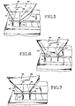
- Exit funnel 58 ( Figure 11 ) is positioned approximately perpendicular to transport tube 38. In the embodiment shown, this is at least 34° from the horizontal. The angle is sufficient to result in the packages moving readily downwardly through the exit funnel structure, i.e. the angle is greater than the angle of repose for the packaged medications.
- exit funnel 58 is a square box or tray, open at the top end where the medications are received, 760mm, (30 inches) on a side by 200mm (8 inches) deep, made from stainless steel.
- Exit funnel 58 includes a flat back surface 59 and two opposing flat side walls 60 and 61.
- exit funnel 58 At the lower end of exit funnel 58, extending from the lower edges of sides 60 and 61, are opposing flat diverter members 62 and 64, each approximately 200mm (8 inches) high.
- the diverter members are pivoted about pivot points 66 and 68, respectively, by flat pivot members 67 and 69 ( Figure 5 ).
- the diverters move directly toward and away from each other, by means of air cylinders.
- the diverters 62 and 64 angle inwardly at an angle of approximately 65*
- the diverters are controlled independently so that the lower end of each diverter can move to one side a distance of 89mm (3.5 inches).
- This arrangement allows for four different combinations of diverter openings at the lower end of the exit funnel, e.g. fully closed, fully open 178mm (7 inch) wide opening), the right diverter opened 89mm(3-1/2 inches) to the right, and the left diverter opened for 89mm (3-1/2 inches) to the left.
- At the bottom edge of each diverter are short, flexible flap members 70 and 72.
- the flap members are approximately 89mm (3.5 inches) long and 36mm (1.4 inches) high. They help to guide the medications into the medication bins.
- This arrangement in the embodiment shown allows the loading system to fill a cell 73 ( Figure 12 ) comprising two adjacent sectors of 89 (3.5 inches) or two adjacent cells 77, 79 comprising one sector, each 89mm (3.5 inches), while the cart remains in a single position.
- a single patient with a two sector cell, or two patients with one sector cells can be filled while the cart remains in one position.
- the opening at the lower end of the two diverter elements 62 and 64 will be such as to provide filling for at least one cell in each bin (for one patient) while the cart is in one particular position. While use of the structure described above, with movable diverters and a particular sector arrangement, permits the filling of more than one sector without moving the cart, it should be understood that such a capability is not necessary to the present invention.
- a plastic lid 75 overlays part of the exit funnel structure, forming in effect a partial front panel surface, extending basically over the diverter elements. Lid 75 is hinged about its upper edge 76 to the lower end of the exit funnel box side walls 60 and 61. If, in operation of the system, medication packages become jammed within the exit funnel, particularly in the diverter portion, it is simple and fast for an operator to lift lid 75 and clear the jam by hand.
- Doors are provided in the upper surface of the cart and controlled so as to give access only to the particular cell associated with the patient being served.
- the system receives medications prescribed for each patient in the facility in turn from the automatically controlled medication storage vaults, moves these collected medications via a transport tube into the exit funnel assembly, from which they fall into the cell in a portion of a medication bin assigned to the patient.
- the cart is positioned as described below, and the bins within the cart are controlled so that the control computer 23 of the system knows that one particular portion of a particular bin assigned to a patient in fact contains medications dispensed for that patient.
- a medication cart having generally the structure, arrangement and control capability referred to above is shown in U.S. patent application serial No. 09/204,814 , which is assigned to the same assignee as the present invention. That application shows the details of a medication cart, the details of a bin arrangement and a mechanism for controlling the movement of the bins within the cart as well as access to the bins, so that the prescribed medications for a particular patient are available when requested, are under computer control. Access is provided to the nurse or other practitioner administering the medications by a series of controlled access doors at the top of the cart, which uncover only the portion of the bin assigned to a given patient.
- a cart or carts 22 are positioned by hand on guide rail 80, as shown in Figures 13 and 14 .
- a two-rail arrangement could also be used, as shown in Figure 1 .
- the wheels on the bottom of the cart ride on the rail.
- an endless chain 85 driven by a stepper motor, is used to move the cart 22 in precise, known increments along the rail.
- An alternative arrangement to produce a precise movement of the cart is a lead screw. Other systems could also be used.
- the cart In operation, the cart is moved onto the guide rail by an operator and connected to the drive system in the home position, which is known by the control computer 23.
- the control system thus knows where the cart is in relation to the exit funnel structure 38 of the medication handling system and hence, the position of the medication bins within the cart as well relative to the exit funnel.
- the cart is then moved through a series of steps of known distance.
- the cart is locked into place.
- the medications for the patient assigned to that cell are then transported from the storage assemblies and loaded into that cell through the exit funnel.
- the medications fall by gravity into the cell.
- the diverters 62 and 64 on the lower end of the exit funnel have been properly positioned to produce a feed of the medications into the correct cell in the medication bin or other receptacle.
- An overweight sensor 84 on the cart checks to ensure that all medications are within the height of the bin. If not, an alarm is generated, so that an operator can correct the situation.
- the overheight sensor could be positioned on the diverters. In the embodiment shown, two adjacent 89mm (3.5 inch) sectors can be filled, either for one patient or two patients, without moving the cart. For the 178mm (7.0 inch) cell, both diverters must be fully open.
- the bins are moved so that the next bin in the bin sequence is moved into position for filling. After the first cells in each bin have been filled, the next set of cells for all of the bins is filled. This continues until all the cells in all the bins in the cart have been filled. Then, the operator will release the cart from the guide rail system and move the cart away from the loading system. The next cart is then moved onto the rail system and attached to the carriage in the home position. The filled cart is moved up to the appropriate ward for administration of the medications to the patients.
- FIGS 8-10 show the supplemental doses assembly 26.
- the supplemental doses assembly comprises a tray-like structure, shown generally at 86, which is divided into a number of separate compartments by a plurality of divider walls.
- the compartments are arranged to be of different sizes to accommodate different size medication packages and other medical supplies.
- Each of the compartments is closed on all sides, except for one, by the compartment walls and a bottom plate.
- the otherwise open side of each of the compartments has hinged doors 90-90 which are used to close off the compartments.
- the doors 90 are controlled to be individually openable with an electrical signal command, by means of solenoids or the like.
- the assembly 26 is shown with its access side up in Figures 9 and 10 , showing the compartments and the movement of the access doors.
- the door side of the assembly in the embodiment shown is positioned over the exit funnel assembly 58, as shown generally in Figure 1 , during loading of the medications into the medication bins.
- the assembly is supported on a separate frame 92 by means of opposing pins 94 on which the assembly is rotatable. Another set of spring-loaded pins (not shown) are used to fix the assembly in a particular position.
- frame 92 is moved away from the cart and the two position pins are pulled away and the assembly is rotated 180° about opposing pins 94-94 to provide access to the compartments. All the doors are then opened and those medications which are to be loaded in the assembly are loaded into the various compartments. Those medications are typically preselected by hand from the central pharmacy.
- each of the medications picked will have a bar code or similar identifier on the packaging.
- This bar code will be scanned by an operator using a bar code reader; the package will be placed in a particular compartment, which also has an identification. This identification is also scanned, so that the location of the supplemental medications in the supplemental doses assembly is known. This information is provided to the central computer. In some systems it will not be necessary to have an identifier on the compartments.
- the assembly is rotated again, fixed in position, and moved back against the exit funnel. Then as each patient's medications are dispensed from the storage assemblies in turn and moved into the exit funnel, the doors on the compartments containing the medications for that patient are opened automatically and fall into the exit funnel.
- the assembly in the embodiment shown is an automatic supplemental doses assembly.
- the combined medications move by gravity down into the appropriate patient cell in the cart.
- the frame assembly can be supported on the exit funnel structure itself.
- the supporting pins 94 can be made slidable along a track so that the assembly can be moved away from its operating position against the exit funnel, rotated for filling, and then moved back for actual use.
- the supplemental doses assembly is filled at the beginning of each run, i.e. all of the supplemental medications for patients in a given medication cart are loaded at one time.
- An alternative location for the supplemental doses assembly is in the vicinity of the storage vaults.
- the supplemental medications fall down a separate funnel structure into the transport tube, like the other medications.
- This alternative arrangement may be more convenient and easier to manipulate than the arrangement shown in Figure 1 and discussed above.
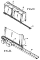
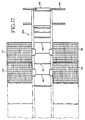
- Figures 15-17 show another embodiment of the transport/loading system of the present invention, which in many situations will be preferred.
- the medication vaults which each comprise a plurality of automatically controlled individual storage cartridges, are generally rectangular in shape. Each vault contains approximately 150 cartridges, although this can be varied.
- four such medication vaults or assemblies are shown at 98-101.
- these medication vaults are provided in opposing pairs with as many pairs of vaults as may be required. This overcomes a disadvantage with the embodiment of Figures 1-4 , in which the number of medication vaults is limited by the particular geometric arrangement of that embodiment
- the collecting mechanism and the transport tube are replaced by a conveyor, shown generally at 106.
- the conveyor 106 has a horizontal portion 108 and an inclined portion 110.
- Medication vaults are positioned on opposite sides of the horizontal portion 108.
- the length of horizontal portion 108 will vary, depending upon the number of vaults used in the system.
- Medications from the storage vaults will be moved onto the conveyor 106 through individual medication funnels.
- the funnels are actually simpler and more straightforward than in the embodiment shown in Figures 1-4 .
- the funnels simply direct the medications dispensed automatically from the storage assemblies onto the conveyor 106.
- a supplemental doses assembly can also be positioned along the horizontal portion 108 of the conveyor at a selected location, preferably at the rear end (start) 111 thereof, where access to the supplemental doses assembly is more convenient for hand-loading.
- the supplemental doses assembly can be positioned on a frame which would extend over the conveyor.
- the supplemental doses assembly tray can be similar to that shown in Figure 7 , rotatably mounted on supporting pins on the frame.
- the conveyor will vary in the length of the horizontal portion 108, but will be approximately 460mm (18 inches) wide over its entire length. Typically, the conveyor will be made of rubber, and will be supported at various points along its length. The conveyor will have an upper surface 112 upon which the medications are positioned, and a lower "return" surface which is separated from the upper surface by a few inches.
- Flights 120 are in the embodiment shown approximately 76mm (3 inches) high.
- the conveyor in the embodiment shown is driven by a belt 125 with a stepper motor 127, the belt engaging conveyor driving wheels 129 which are positioned at the top of the conveyor.
- the exit funnel 131 includes diverter arms similar to that shown in Figures 5-7 .
- the arrangement of Figures 15-17 has some advantages over the embodiment of Figures 1-4 , in that it is generally simpler in structure and operation and has the further advantage of being able to accommodate a variable number of automatic medication-dispensing vaults, depending upon the number necessary for a particular health care facility. For instance, two opposing vaults could be used for a smaller facility, while six or even more vaults could be used for a large facility. Also, it is easy to accommodate a supplemental doses assembly along the horizontal portion of a conveyor instead of adjacent the exit funnel, although the supplemental doses assembly could be positioned at that location as well in this embodiment, if so desired.
- a medication dispensing system which collects medications, typically patient-specific medications, which have been automatically dispensed from several medication vaults and moves them in a simple, reliable manner to an exit funnel which in turn directs them into patient-specific portions of a medication bin in a medication cart.
- the medication cart can then be moved directly to the patient's bedside.
- the medication cart will have the medications for all patients located within a particular area, such as a ward.
- the present system is thus a medication handling system which in typically used intermediate of an automatic medication dispensing system and a medication cart, which moves the medications to the patient.
- the invention could be used, however, with other medication containers, such as different kinds of receptacles, including courier envelopes or transport bins.
Landscapes
- Health & Medical Sciences (AREA)
- Life Sciences & Earth Sciences (AREA)
- Animal Behavior & Ethology (AREA)
- General Health & Medical Sciences (AREA)
- Public Health (AREA)
- Veterinary Medicine (AREA)
- Medical Preparation Storing Or Oral Administration Devices (AREA)
- Accommodation For Nursing Or Treatment Tables (AREA)
- Handcart (AREA)
Claims (17)
- Système de manipulation de médicaments (10) pour manipuler des médicaments emballés présélectionnés distribués à partir d'une pluralité d'ensembles de stockage (12), comprenant :un ensemble de réception de médicaments (30) pour collecter les médicaments qui ont été automatiquement distribués à partir d'un ensemble de stockage (12) ; un ensemble de chargement de médicaments ; etdes moyens pour transporter les médicaments collectés jusqu'à l'ensemble de chargement de médicaments ; l'ensemble de réception de médicaments étant agencé pour fournir les médicaments collectés aux moyens de transport, et les moyens de transport étant inclinés vers le haut entre l'ensemble de réception et l'ensemble de chargement, et les moyens de transport comprenant un convoyeur sans fin (106) ayant une partie horizontale (108) et une partie inclinée (110), dans lequel la partie horizontale (108) est agencée pour recevoir le long de ses côtés opposés, une pluralité d'ensembles de stockage de médicaments (12), à partir desquels les médicaments sont distribués sur le convoyeur (106), le convoyeur (106) comprenant une pluralité de déflecteurs latéraux espacés (120) le long de sa longueur et des moyens pour déplacer le convoyeur (127) afin de transporter des médicaments sur ce dernier jusqu'à l'ensemble de chargement de médicaments, dont une entrée se trouve au niveau d'une extrémité supérieure de la partie inclinée (110) du convoyeur (106), le système comprenant ledit ensemble de chargement de médicaments positionné par rapport aux moyens de transport et configuré de sorte que les médicaments emballés se déplacent par l'action de la gravité hors d'une extrémité inférieure de l'ensemble de chargement jusqu'à un réceptacle de médicaments, l'extrémité inférieure de l'ensemble de chargement étant configurée afin de guider les médicaments emballés directement dans une partie sélectionnée d'un réceptacle de médicaments.
- Système de manipulation de médicaments (10) pour manipuler des médicaments emballés présélectionnés distribués à partir d'une pluralité d'ensembles de stockage (12), comprenant :un ensemble de réception de médicaments (30) pour collecter des médicaments qui ont été automatiquement distribués à partir d'un ensemble de stockage (12) ; un ensemble de chargement de médicaments ; et des moyens pour transporter les médicaments collectés jusqu'à l'ensemble de chargement de médicaments ; l'ensemble de réception de médicaments étant agencé pour fournir les médicaments collectés aux moyens de transport, et les moyens de transport étant inclinés vers le haut entre l'ensemble de réception et l'ensemble de chargement, et se présentant sous la forme d'un tube (38) et comprenant un élément poussoir (42) qui a une profil légèrement inférieur au tube (38), les moyens de transport comprenant en outre un élément motorisé qui se déplace entre des extrémités opposées du tube de transport (38) pour déplacer les médicaments qui sont tombés dans le tube au niveau de son extrémité jusqu'à une extrémité opposée du tube de transport (38), où ils se déplacent dans l'ensemble de chargement, le système comprenant ledit ensemble de chargement de médicaments positionné par rapport aux moyens de transport et configuré de sorte que les médicaments emballés se déplacent par gravité hors d'une extrémité inférieure de l'ensemble de chargement jusqu'à un réceptacle de médicaments, l'extrémité inférieure de l'ensemble de chargement étant configurée afin de guider les médicaments emballés directement dans une partie sélectionnée d'un réceptacle de médicaments.
- Système (10) selon la revendication 1 ou 2, dans lequel le réceptacle de médicaments est un bac de médicaments présent dans un chariot de médicaments (22).
- Système (10) selon la revendication 1 ou 2, comprenant une paire de déflecteurs opposés (62, 64) au niveau de l'extrémité inférieure de l'ensemble de chargement pour guider les médicaments dans le réceptacle de médicaments.
- Système (10) selon la revendication 1 ou 2, dans lequel ladite partie sélectionnée est associée à un patient particulier et lesdits médicaments emballés ont été prescrits pour ledit patient particulier.
- Système (10) selon la revendication 1 ou 2, dans lequel ladite partie sélectionnée est spécifique pour les médicaments.
- Système (10) selon la revendication 1 ou 2, dans lequel l'inclinaison est de l'ordre de 35°-55°.
- Système (10) selon la revendication 1 ou 2, dans lequel l'inclinaison est à un angle tel que les médicaments emballés se déplacent librement par la gravité hors de l'ensemble de chargement dans le chariot de médicaments (22),
- Système (10) selon la revendication 4, comprenant une paire de déflecteurs (62, 64) au niveau de l'extrémité inférieure de l'ensemble de chargement et des moyens pour contrôler la position des déflecteurs (62, 64) de sorte qu'on peut remplir plus d'une section dans un bac de médicaments avec des médicaments sans déplacer le chariot (22).
- Système (10) selon la revendication 9, comprenant des parties plates souples (70, 72) s'étendant à partir des extrémités des bras de déflecteur (62, 64) afin de garantir que les médicaments tombent dans la partie sélectionnée du bac de médicaments.
- Système (10) selon la revendication 1 ou 2, dans lequel l'ensemble de réception (30) comprend un agencement d'entonnoir (32) en bas duquel les médicaments reçus se déplacent par gravité sur les moyens de transport.
- Système selon la revendication 4, dans lequel les moyens de déflecteur (62, 64) comprennent une paire de bras de déviation opposés qui sont montés pour se déplacer vers et à distance l'un de l'autre, augmentant/diminuant une ouverture de sortie au niveau d'une extrémité inférieure de l'ensemble de chargement.
- Système selon la revendication 12, comprenant un couvercle mobile (75) recouvrant les bras de déviation opposés qui peuvent être déplacés afin de permettre un accès pratique à l'ensemble de chargement dans la zone des bras de déviation.
- Système selon la revendication 1 ou 2, comprenant un ensemble de doses supplémentaires (26) positionné de manière adjacente à l'ensemble de chargement pour ajouter des médicaments sélectionnés non disponibles à partir des ensembles de stockage (12).
- Système selon la revendication 1 ou 2, dans lequel l'ensemble de doses supplémentaires (26) comprend une pluralité de compartiments pouvant recevoir des médicaments, chaque compartiment ayant une porte de compartiment contrôlable qui, lorsqu'elle est activée, s'ouvre de sorte que le médicament à l'intérieur de cette dernière se déplace dans l'ensemble de chargement.
- Système selon la revendication 15, dans lequel les portes de compartiment sont contrôlables de sorte que seules ces portes de compartiment qui contiennent des médicaments supplémentaires pour un patient particulier sont ouvertes conjointement avec lesdits médicaments pour ledit patient qui sont distribués à partir de coffrets de médicaments, de sorte que les médicaments supplémentaires et les médicaments distribués sont dirigés ensemble dans le bac de médicaments.
- Système selon la revendication 14 lorsqu'elle dépend de la revendication 1, comprenant un ensemble de doses supplémentaires (26) positionné au-dessus de la partie horizontale (108) du convoyeur (106).
Applications Claiming Priority (3)
| Application Number | Priority Date | Filing Date | Title |
|---|---|---|---|
| US09/324,682 US6354783B1 (en) | 1999-06-03 | 1999-06-03 | Medication-handling system for use in loading medication carts |
| US324682 | 1999-06-03 | ||
| PCT/US2000/015441 WO2000075050A1 (fr) | 1999-06-03 | 2000-06-01 | Systeme de manipulation de medicaments utilise pour charger des chariots a medicaments |
Publications (3)
| Publication Number | Publication Date |
|---|---|
| EP1198397A1 EP1198397A1 (fr) | 2002-04-24 |
| EP1198397A4 EP1198397A4 (fr) | 2006-12-27 |
| EP1198397B1 true EP1198397B1 (fr) | 2012-02-01 |
Family
ID=23264640
Family Applications (1)
| Application Number | Title | Priority Date | Filing Date |
|---|---|---|---|
| EP00939569A Expired - Lifetime EP1198397B1 (fr) | 1999-06-03 | 2000-06-01 | Systeme de manipulation de medicaments utilise pour charger des chariots a medicaments |
Country Status (7)
| Country | Link |
|---|---|
| US (1) | US6354783B1 (fr) |
| EP (1) | EP1198397B1 (fr) |
| AT (1) | ATE543758T1 (fr) |
| AU (1) | AU776549B2 (fr) |
| CA (1) | CA2375750C (fr) |
| ES (1) | ES2381332T3 (fr) |
| WO (1) | WO2000075050A1 (fr) |
Families Citing this family (17)
| Publication number | Priority date | Publication date | Assignee | Title |
|---|---|---|---|---|
| US6847861B2 (en) * | 2001-11-30 | 2005-01-25 | Mckesson Automation, Inc. | Carousel product for use in integrated restocking and dispensing system |
| US20040158507A1 (en) * | 2002-12-06 | 2004-08-12 | Meek Robert B. | Inventory management and replenishment system |
| US7052097B2 (en) * | 2002-12-06 | 2006-05-30 | Mckesson Automation, Inc. | High capacity drawer with mechanical indicator for a dispensing device |
| US7698019B2 (en) | 2003-11-03 | 2010-04-13 | Tech Pharmacy Services, Inc. | System and software of enhanced pharmaceutical operations in long-term care facilities and related methods |
| CA2752578C (fr) * | 2003-11-26 | 2016-02-02 | Mckesson Automation Inc. | Suite integree d'instruments medicaux |
| US8036773B2 (en) * | 2006-05-10 | 2011-10-11 | Mckesson Automation Inc. | System, method and corresponding apparatus for storing, retrieving and delivering unit dose blisters |
| US20080270178A1 (en) * | 2007-04-30 | 2008-10-30 | Mckesson Specialty Distribution Llc | Inventory Management System For A Medical Service Provider |
| US8009913B2 (en) * | 2007-05-29 | 2011-08-30 | Mckesson Automation, Inc. | System, method, apparatus and computer program product for capturing human-readable text displayed on a unit dose package |
| US8280550B2 (en) | 2008-06-17 | 2012-10-02 | Omnicell, Inc. | Cabinet with remote integration |
| US9978110B2 (en) * | 2007-06-19 | 2018-05-22 | Omnicell, Inc. | Patient-specific bin assignment systems, methods, and devices |
| ITPR20080019A1 (it) * | 2008-03-19 | 2009-09-20 | Ingegneria Biomedica Santa Lucia Spa | Metodo e dispositivo per lo stoccaggio e la distrubuzione di articoli farmaceutici suddivisi in dosi unitarie o unita' posologiche. |
| US8929641B2 (en) | 2009-03-17 | 2015-01-06 | Aesynt Incorporated | System and method for determining the orientation of a unit dose package |
| US20120271454A1 (en) * | 2009-12-03 | 2012-10-25 | Goto Makoto | Medicine collecting system and cart |
| US20110172815A1 (en) * | 2010-01-11 | 2011-07-14 | Jvm Co., Ltd. | Medicine management apparatus and method, bin for the apparatus, and cart for the apparatus |
| US8515575B2 (en) | 2010-07-19 | 2013-08-20 | Paragon Technologies, Inc. | Mobile automatic order selection system capable of responding to simultaneous order requests |
| JP6355881B2 (ja) * | 2011-08-26 | 2018-07-11 | 株式会社タカゾノテクノロジー | 薬剤分包装置 |
| KR102089650B1 (ko) | 2012-11-19 | 2020-03-16 | 옴니셀 인코포레이티드 | 다수의 rfid 리더를 이용한 저장 캐비넷 |
Citations (3)
| Publication number | Priority date | Publication date | Assignee | Title |
|---|---|---|---|---|
| DE3728212C1 (de) * | 1987-08-24 | 1989-01-05 | Sortimat Creuz & Co Gmbh | Vorrichtung zum lagerichtigen Zufuehren |
| DE3742728C1 (en) * | 1987-12-17 | 1989-03-23 | Goessling Gmbh & Co Kg Dr Ing | Apparatus for disentangling and for forming small portions from a chaotic batch of mass-produced parts |
| US5875883A (en) * | 1996-08-14 | 1999-03-02 | Dorner Mfg. Corp | Adjustable inclined conveyor |
Family Cites Families (15)
| Publication number | Priority date | Publication date | Assignee | Title |
|---|---|---|---|---|
| GB1009841A (en) * | 1961-02-14 | 1965-11-17 | Automotive Prod Co Ltd | Improvements in and relating to the mechanical filling of trucks or other containerswith coal or other solid substances |
| US3310199A (en) * | 1965-03-22 | 1967-03-21 | Ethicon Inc | Article dispensing units removable from an enclosing casing |
| DE3146598A1 (de) | 1981-11-25 | 1983-07-07 | Hoechst Ag, 6230 Frankfurt | "neue peptide und verfahren zu ihrer herstellung" |
| US4546901A (en) * | 1984-02-02 | 1985-10-15 | Buttarazzi Patrick J | Apparatus for dispensing medication |
| JPS6274808A (ja) * | 1985-09-27 | 1987-04-06 | Itoki Kosakusho Co Ltd | フアイルフオルダの自動取出し収納装置における緊急出庫装置 |
| US4655026A (en) * | 1985-12-11 | 1987-04-07 | Wigoda Luis T | Pill dispensing machine |
| US4785969A (en) | 1986-11-10 | 1988-11-22 | Pyxis Corporation | Medication dispensing system |
| IT1233671B (it) * | 1989-08-01 | 1992-04-13 | Gd Spa | Apparecchiatura per alimentare macchine confezionatrici con pile di materiale in foglio |
| US5011240A (en) | 1989-11-28 | 1991-04-30 | Milcare, Inc. | Segmented side wall cart |
| US5348061B1 (en) * | 1992-12-01 | 1999-10-12 | Baxter Int | Tablet accumulator for an automated prescription vial filling system |
| US5314243A (en) | 1992-12-04 | 1994-05-24 | Automated Healthcare, Inc. | Portable nursing center |
| US5431299A (en) * | 1994-01-26 | 1995-07-11 | Andrew E. Brewer | Medication dispensing and storing system with dispensing modules |
| US5988858A (en) * | 1995-06-09 | 1999-11-23 | Kabushiki Kaisha Yuyama Seiksakusho | Method and apparatus for delivering drugs |
| DE19757963C2 (de) * | 1997-12-24 | 2000-08-03 | P & P Materialflussysteme Gmbh | Vorrichtung zum automatischen Kommissionieren von Stückgut |
| US6219587B1 (en) * | 1998-05-27 | 2001-04-17 | Nextrx Corporation | Automated pharmaceutical management and dispensing system |
-
1999
- 1999-06-03 US US09/324,682 patent/US6354783B1/en not_active Expired - Lifetime
-
2000
- 2000-06-01 EP EP00939569A patent/EP1198397B1/fr not_active Expired - Lifetime
- 2000-06-01 ES ES00939569T patent/ES2381332T3/es not_active Expired - Lifetime
- 2000-06-01 CA CA2375750A patent/CA2375750C/fr not_active Expired - Lifetime
- 2000-06-01 WO PCT/US2000/015441 patent/WO2000075050A1/fr not_active Ceased
- 2000-06-01 AT AT00939569T patent/ATE543758T1/de active
- 2000-06-01 AU AU54639/00A patent/AU776549B2/en not_active Expired
Patent Citations (3)
| Publication number | Priority date | Publication date | Assignee | Title |
|---|---|---|---|---|
| DE3728212C1 (de) * | 1987-08-24 | 1989-01-05 | Sortimat Creuz & Co Gmbh | Vorrichtung zum lagerichtigen Zufuehren |
| DE3742728C1 (en) * | 1987-12-17 | 1989-03-23 | Goessling Gmbh & Co Kg Dr Ing | Apparatus for disentangling and for forming small portions from a chaotic batch of mass-produced parts |
| US5875883A (en) * | 1996-08-14 | 1999-03-02 | Dorner Mfg. Corp | Adjustable inclined conveyor |
Also Published As
| Publication number | Publication date |
|---|---|
| WO2000075050A1 (fr) | 2000-12-14 |
| EP1198397A4 (fr) | 2006-12-27 |
| ATE543758T1 (de) | 2012-02-15 |
| AU5463900A (en) | 2000-12-28 |
| ES2381332T3 (es) | 2012-05-25 |
| CA2375750A1 (fr) | 2000-12-14 |
| EP1198397A1 (fr) | 2002-04-24 |
| US6354783B1 (en) | 2002-03-12 |
| CA2375750C (fr) | 2010-04-06 |
| AU776549B2 (en) | 2004-09-16 |
Similar Documents
| Publication | Publication Date | Title |
|---|---|---|
| EP1198397B1 (fr) | Systeme de manipulation de medicaments utilise pour charger des chariots a medicaments | |
| AU768321B2 (en) | Automated pharmaceutical management and dispensing system | |
| US11649115B2 (en) | Apparatus and methods for automated picking of items | |
| AU766931B2 (en) | Automated medication-dispensing cart | |
| US5761877A (en) | System for individual dosage medication distribution | |
| US5405048A (en) | Vacuum operated medicine dispenser | |
| US6490502B2 (en) | Article dispensing system | |
| KR101762965B1 (ko) | 약제학적 분배 시스템 및 관련된 방법 | |
| US6370841B1 (en) | Automated method for dispensing bulk medications with a machine-readable code | |
| US5460294A (en) | Single dose pharmaceutical dispenser subassembly | |
| US7194333B2 (en) | Pharmacy envelope dispensing arrangement | |
| JP4259811B2 (ja) | 薬剤供給装置 | |
| CA2129137A1 (fr) | Accumulateur de comprimes pour systeme automatise de remplissage de vials | |
| EP0208029A1 (fr) | Appareil pour la distribution de médicaments | |
| KR100415736B1 (ko) | 약제분배기및약제분배방법 | |
| CA2520414A1 (fr) | Distributeur medical fonctionnant sous vide |
Legal Events
| Date | Code | Title | Description |
|---|---|---|---|
| PUAI | Public reference made under article 153(3) epc to a published international application that has entered the european phase |
Free format text: ORIGINAL CODE: 0009012 |
|
| 17P | Request for examination filed |
Effective date: 20011213 |
|
| AK | Designated contracting states |
Kind code of ref document: A1 Designated state(s): AT BE CH CY DE DK ES FI FR GB GR IE IT LI LU MC NL PT SE |
|
| AX | Request for extension of the european patent |
Free format text: AL;LT;LV;MK;RO;SI |
|
| A4 | Supplementary search report drawn up and despatched |
Effective date: 20061129 |
|
| RIC1 | Information provided on ipc code assigned before grant |
Ipc: A61J 7/00 20060101ALI20061123BHEP Ipc: B65G 1/10 20060101AFI20001219BHEP |
|
| RAP1 | Party data changed (applicant data changed or rights of an application transferred) |
Owner name: OMNICELL, INC. |
|
| 17Q | First examination report despatched |
Effective date: 20070529 |
|
| GRAP | Despatch of communication of intention to grant a patent |
Free format text: ORIGINAL CODE: EPIDOSNIGR1 |
|
| GRAS | Grant fee paid |
Free format text: ORIGINAL CODE: EPIDOSNIGR3 |
|
| GRAA | (expected) grant |
Free format text: ORIGINAL CODE: 0009210 |
|
| AK | Designated contracting states |
Kind code of ref document: B1 Designated state(s): AT BE CH CY DE DK ES FI FR GB GR IE IT LI LU MC NL PT SE |
|
| REG | Reference to a national code |
Ref country code: GB Ref legal event code: FG4D |
|
| REG | Reference to a national code |
Ref country code: AT Ref legal event code: REF Ref document number: 543758 Country of ref document: AT Kind code of ref document: T Effective date: 20120215 Ref country code: CH Ref legal event code: EP |
|
| REG | Reference to a national code |
Ref country code: DE Ref legal event code: R096 Ref document number: 60046890 Country of ref document: DE Effective date: 20120329 |
|
| REG | Reference to a national code |
Ref country code: ES Ref legal event code: FG2A Ref document number: 2381332 Country of ref document: ES Kind code of ref document: T3 Effective date: 20120525 |
|
| REG | Reference to a national code |
Ref country code: NL Ref legal event code: VDEP Effective date: 20120201 |
|
| PG25 | Lapsed in a contracting state [announced via postgrant information from national office to epo] |
Ref country code: NL Free format text: LAPSE BECAUSE OF FAILURE TO SUBMIT A TRANSLATION OF THE DESCRIPTION OR TO PAY THE FEE WITHIN THE PRESCRIBED TIME-LIMIT Effective date: 20120201 |
|
| PG25 | Lapsed in a contracting state [announced via postgrant information from national office to epo] |
Ref country code: PT Free format text: LAPSE BECAUSE OF FAILURE TO SUBMIT A TRANSLATION OF THE DESCRIPTION OR TO PAY THE FEE WITHIN THE PRESCRIBED TIME-LIMIT Effective date: 20120601 Ref country code: BE Free format text: LAPSE BECAUSE OF FAILURE TO SUBMIT A TRANSLATION OF THE DESCRIPTION OR TO PAY THE FEE WITHIN THE PRESCRIBED TIME-LIMIT Effective date: 20120201 Ref country code: GR Free format text: LAPSE BECAUSE OF FAILURE TO SUBMIT A TRANSLATION OF THE DESCRIPTION OR TO PAY THE FEE WITHIN THE PRESCRIBED TIME-LIMIT Effective date: 20120502 Ref country code: FI Free format text: LAPSE BECAUSE OF FAILURE TO SUBMIT A TRANSLATION OF THE DESCRIPTION OR TO PAY THE FEE WITHIN THE PRESCRIBED TIME-LIMIT Effective date: 20120201 |
|
| REG | Reference to a national code |
Ref country code: AT Ref legal event code: MK05 Ref document number: 543758 Country of ref document: AT Kind code of ref document: T Effective date: 20120201 |
|
| PG25 | Lapsed in a contracting state [announced via postgrant information from national office to epo] |
Ref country code: CY Free format text: LAPSE BECAUSE OF FAILURE TO SUBMIT A TRANSLATION OF THE DESCRIPTION OR TO PAY THE FEE WITHIN THE PRESCRIBED TIME-LIMIT Effective date: 20120201 |
|
| PG25 | Lapsed in a contracting state [announced via postgrant information from national office to epo] |
Ref country code: SE Free format text: LAPSE BECAUSE OF FAILURE TO SUBMIT A TRANSLATION OF THE DESCRIPTION OR TO PAY THE FEE WITHIN THE PRESCRIBED TIME-LIMIT Effective date: 20120201 Ref country code: DK Free format text: LAPSE BECAUSE OF FAILURE TO SUBMIT A TRANSLATION OF THE DESCRIPTION OR TO PAY THE FEE WITHIN THE PRESCRIBED TIME-LIMIT Effective date: 20120201 |
|
| PLBE | No opposition filed within time limit |
Free format text: ORIGINAL CODE: 0009261 |
|
| STAA | Information on the status of an ep patent application or granted ep patent |
Free format text: STATUS: NO OPPOSITION FILED WITHIN TIME LIMIT |
|
| 26N | No opposition filed |
Effective date: 20121105 |
|
| PG25 | Lapsed in a contracting state [announced via postgrant information from national office to epo] |
Ref country code: MC Free format text: LAPSE BECAUSE OF NON-PAYMENT OF DUE FEES Effective date: 20120630 Ref country code: AT Free format text: LAPSE BECAUSE OF FAILURE TO SUBMIT A TRANSLATION OF THE DESCRIPTION OR TO PAY THE FEE WITHIN THE PRESCRIBED TIME-LIMIT Effective date: 20120201 |
|
| REG | Reference to a national code |
Ref country code: CH Ref legal event code: PL |
|
| REG | Reference to a national code |
Ref country code: CH Ref legal event code: PL |
|
| REG | Reference to a national code |
Ref country code: DE Ref legal event code: R097 Ref document number: 60046890 Country of ref document: DE Effective date: 20121105 |
|
| REG | Reference to a national code |
Ref country code: IE Ref legal event code: MM4A |
|
| PG25 | Lapsed in a contracting state [announced via postgrant information from national office to epo] |
Ref country code: CH Free format text: LAPSE BECAUSE OF NON-PAYMENT OF DUE FEES Effective date: 20120630 Ref country code: LI Free format text: LAPSE BECAUSE OF NON-PAYMENT OF DUE FEES Effective date: 20120630 Ref country code: IE Free format text: LAPSE BECAUSE OF NON-PAYMENT OF DUE FEES Effective date: 20120601 |
|
| REG | Reference to a national code |
Ref country code: DE Ref legal event code: R082 Ref document number: 60046890 Country of ref document: DE Representative=s name: BOCKHORNI & KOLLEGEN PATENT- UND RECHTSANWAELT, DE Ref country code: DE Ref legal event code: R082 Ref document number: 60046890 Country of ref document: DE Representative=s name: HEYER, VOLKER, DIPL.-PHYS. DR.RER.NAT., DE |
|
| REG | Reference to a national code |
Ref country code: DE Ref legal event code: R082 Ref document number: 60046890 Country of ref document: DE Representative=s name: HEYER, VOLKER, DIPL.-PHYS. DR.RER.NAT., DE |
|
| PG25 | Lapsed in a contracting state [announced via postgrant information from national office to epo] |
Ref country code: LU Free format text: LAPSE BECAUSE OF NON-PAYMENT OF DUE FEES Effective date: 20120601 |
|
| REG | Reference to a national code |
Ref country code: FR Ref legal event code: PLFP Year of fee payment: 17 |
|
| REG | Reference to a national code |
Ref country code: FR Ref legal event code: PLFP Year of fee payment: 18 |
|
| REG | Reference to a national code |
Ref country code: FR Ref legal event code: PLFP Year of fee payment: 19 |
|
| PGFP | Annual fee paid to national office [announced via postgrant information from national office to epo] |
Ref country code: IT Payment date: 20190620 Year of fee payment: 20 Ref country code: DE Payment date: 20190521 Year of fee payment: 20 |
|
| PGFP | Annual fee paid to national office [announced via postgrant information from national office to epo] |
Ref country code: FR Payment date: 20190410 Year of fee payment: 20 |
|
| PGFP | Annual fee paid to national office [announced via postgrant information from national office to epo] |
Ref country code: GB Payment date: 20190529 Year of fee payment: 20 Ref country code: ES Payment date: 20190701 Year of fee payment: 20 |
|
| REG | Reference to a national code |
Ref country code: DE Ref legal event code: R071 Ref document number: 60046890 Country of ref document: DE |
|
| REG | Reference to a national code |
Ref country code: GB Ref legal event code: PE20 Expiry date: 20200531 |
|
| PG25 | Lapsed in a contracting state [announced via postgrant information from national office to epo] |
Ref country code: GB Free format text: LAPSE BECAUSE OF EXPIRATION OF PROTECTION Effective date: 20200531 |
|
| REG | Reference to a national code |
Ref country code: ES Ref legal event code: FD2A Effective date: 20200929 |
|
| PG25 | Lapsed in a contracting state [announced via postgrant information from national office to epo] |
Ref country code: ES Free format text: LAPSE BECAUSE OF EXPIRATION OF PROTECTION Effective date: 20200602 |