EP1198051A2 - Power generation mechanism for wireless communication devices - Google Patents
Power generation mechanism for wireless communication devices Download PDFInfo
- Publication number
- EP1198051A2 EP1198051A2 EP01123886A EP01123886A EP1198051A2 EP 1198051 A2 EP1198051 A2 EP 1198051A2 EP 01123886 A EP01123886 A EP 01123886A EP 01123886 A EP01123886 A EP 01123886A EP 1198051 A2 EP1198051 A2 EP 1198051A2
- Authority
- EP
- European Patent Office
- Prior art keywords
- wireless communication
- communication device
- electric power
- power generation
- energy
- Prior art date
- Legal status (The legal status is an assumption and is not a legal conclusion. Google has not performed a legal analysis and makes no representation as to the accuracy of the status listed.)
- Withdrawn
Links
Images



Classifications
-
- H—ELECTRICITY
- H02—GENERATION; CONVERSION OR DISTRIBUTION OF ELECTRIC POWER
- H02K—DYNAMO-ELECTRIC MACHINES
- H02K7/00—Arrangements for handling mechanical energy structurally associated with dynamo-electric machines, e.g. structural association with mechanical driving motors or auxiliary dynamo-electric machines
- H02K7/18—Structural association of electric generators with mechanical driving motors, e.g. with turbines
- H02K7/1807—Rotary generators
- H02K7/1853—Rotary generators driven by intermittent forces
-
- H—ELECTRICITY
- H01—ELECTRIC ELEMENTS
- H01H—ELECTRIC SWITCHES; RELAYS; SELECTORS; EMERGENCY PROTECTIVE DEVICES
- H01H2239/00—Miscellaneous
- H01H2239/076—Key stroke generating power
Definitions
- the present invention relates to a wireless communication device for transmitting/receiving radio wave signals on electric power generated by an electric power generation system using natural energy and to how to use the device.
- a conventional technology for switching on/off a household electric appliance or various other equipments by means of control signals or code inputs through remote control or for data transmission through a transmitter has been widely used for home or business applications.
- a technology for determining transmitted data for an electronic lock or remote control, recorded data in a recording medium, or input data entered with a ten-key pad as a user ID code, thereby performing lock/unlock operations has been used for building management and vehicle door lock.
- wireless communication equipments using very weak waves include, for example, a keyless entry system, a door opener, or a mobile telephone receiver (a wearable vibrator separate from a main body of the mobile telephone) .
- ASK amplitude shift keying
- FSK frequency shift keying
- the Radio Law in Japan specifies that no license is required of any user or manufacturer thereof, and thus, it is finding wide application today in various cheap equipments for daily use.
- such a wireless communication equipment consumes a relatively smaller power and it can operate on a primary battery such as a lithium button battery or a dry battery for a long period from a few months to one year.
- a primary battery such as a lithium button battery or a dry battery for a long period from a few months to one year.
- a wireless communication device which includes: a small electric power generation device; signal generation means for generating a control signal or data signal to perform a wireless communication; communication means for transmitting/receivingthecontrolsignalordatasignal generated by the above-described signal generation means; and control means for controlling the above-described signal generation means and the above-described communication means, in which the above-described signal generation means and the above-described communication means are driven by electric power generated by the above-described small electric power generation device under the control of the above-described control means, wherein the above-described communication means performs a communication during the supply of electric power generated by the above-described small electric power generation device.
- display means is provided to indicate that the wireless communication device according to claim 1 is capable of performing a communication while the above-described electric power generation device continuously generates electric power.
- the above-described small electric power generation device is an electric power generation device which includes: a rotational weight with an eccentric center of gravity; an electromagnetic transducer for generating electric power through the rotation of the above-described rotational weight; and a mechanism for converting rotational energy into inertial energy.
- the above-described mechanism according to claim 3 is a flywheel.
- the above-described small electric power generation device is an electric power generation device which includes: a mechanism for storing elastic energy from an elastic element; and a mechanism for converting the elastic energy into rotational energy and then inertial energy.
- the above-described small electric power generation device generates electric power by taking advantage of the above-described inertial energy.
- the above-described wireless communication device according to claim 6 performs a transmission and reception while the above-described rotational energy and inertial energy are generated.
- the above-described wireless communication device according to claim 7 is a wireless communication device built in an electronic lock and a wireless communication device mounted on an automobile, which perform a communication therebetween.
- the above-described wireless communication device according to claim 7 is a wireless communication device built in a mouse pointer, which performs a communication with a computer.
- the above-described wireless communication device according to claim 9 uses very weak waves.
- the above-described wireless communication device according to claim 7 is a wireless communication device built in an electronic wristwatch, which performs a communication with a wireless base station.
- the above-described electronic wristwatch according to claim 11 corrects the time in response to the above-described data signal.
- a device has an automatic power generation mechanism (hereinafter referred to as automatic generating system (AGS)) built therein for generating electric power responsive to the movement of its wearer.
- the AGS consists of a rotor with an eccentric center of gravity, preferably, a rotational weight in the form of unilateral weight with the thicker outer portion and the thinner center portion for a large rotation moment, a speedup wheel train for increasing the ration speed of the rotational weight, a polarized AG rotor which rotates at a high speed through the rotational transmission of the speedup wheel train, an AG stator facing the AG rotor, and a power generating coil wound around the AG stator or an iron core connected to the AG stator.
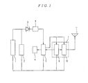
- FIG. 1 is a block diagram for showing an internal circuit of the wireless communication device according to the present invention.
- a limiter circuit 2 with a switching transistor is provided in parallel with a power generating coil 1 in the above-described AGS.
- a rectifier diode 3 is connected in series to the power generating coil 1 to rectify alternating current generated by the power generating coil 1.
- a power supply circuit 6 is a voltage step-down circuit consisting of a smoothing capacitor and a regulator, which causes a wireless circuit 7 described later to generate a direct-current voltage.
- the power supply circuit 6 converts this power into a direct-current power having a voltage of approximately 1 to 2 V and an output current of approximately 1 to 2 mA.
- the power supply circuit 6 supplies driving power to a wireless control circuit 5.
- An indicator 4 provides some indication when a sufficient amount of driving power has been generated and is implemented, for example, with a light-emitting diode indicator or a liquid crystal display for displaying characters. When the indication occurs, the wireless circuit 7 is ready to operate.
- a data signal processing circuit 9 has the function of generating data to be transmitted and the function of determining a received signal. Specifically, it generates a data signal from transmission data consisting of the determination code and ID code for a transmission signal described later or compares the determination code and ID code for a received signal with its corresponding codes stored therein. In the latter case, if these codes match, it communicates to the wireless control circuit 5 that the signal has been received and then informs of it via the indicator 4.
- a wireless signal processing circuit 10 has the functions of modulating transmission data into a high-frequency signal, of demodulating a high-frequency signal to be transmitted or received with an antenna 11, and of reproducing received data. The wireless signal processing circuit 10 requires the largest power consumption among all components of the wireless communication device according to the present invention.
- the wireless circuit can operate only while electric power is generated. This eliminates the need for a secondary battery, thereby providing an equipment which is inherently capable of performing a wireless communication on natural energy only.
- FIG. 2 is a block diagram for showing another internal circuit of the wireless communication device according to the present invention, in which an inertial device is attached to the power generating coil 1.
- the AGS containing the power generating coil 1 converts its vibrational energy into rotational energy in a vibration environment through the rotor with an eccentric center of gravity.
- the inertial device 12 is attached as means for storing any vibrational or forced rotational energy applied to it. This component preserves energy in a mechanical manner and thus, it can continue to rotate on inertial energy for a while even if external energy supply is stopped.
- the attached inertial device 12 can allow the power generating coil 1 to continue its power generation operation for a while, so that the wireless circuit 7 can continue to operate.
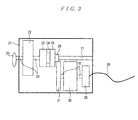
- FIG. 3 shows an internal structure of an electric power generation device 21 when the AGS is provided in combination with the inertial device in the wireless communication device according to the present invention.
- a knob 20 is attached to a shaft 33 so that rotational energy can be applied by hand from outside the device.
- An energy generator 22 is connected to the shaft 33.
- This part of the AGS contains a rotational weight in the form of unilateral weight with the thinner center portion.
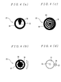
- FIG. 4A shows a rotational weight mechanism of the AGS. When a rotational weight 35 in a cylinder 36 receives vibrations, it rotates about the shaft 33. If vibrational energy is detected and used in the device, the device can operate without the knob 20. Alternatively, if there is no vibration, the knob 20 can be attached for manual rotation.
- FIG. 4B shows an internal structure thereof.
- FIG. 4C shows another implementation of the energy generator 22.
- a spring 40 is used as an energy source.
- the spring 40 is manually wound up by rotating the knob 20 and when the knob 20 is released, the elasticity of the spring 40 causes the shaft 33 to rotate.
- a large force can be obtained instantaneously and then transferred to the toothed rotational wheel 23.
- FIG. 4D shows an example of the pinion and gear wheel.
- the flywheel 30 has a large moment of inertia and therefore can store the inertial energy.
- the spring 40 when the spring 40 is wound back to stop the supply of rotational energy, the rotation can be continued by the inertial energy and the toothed rotational wheel 23.
- the power generating coil 1 can continue to generate electric power.
- the rotational energy is then transferred to the power generating coil 29 via the shaft 32. Generated electric power will be transferred over a cable 28.
- FIG. 5 is a block diagram for showing the wireless circuit portion in the wireless communication device according to the present invention.
- This kind of wireless communication equipment has been developed to use very weak power of waves to gain benefits in terms of cost.
- the present invention has been achieved to provide a wireless circuit which can be driven by natural energy, since natural energy is advantageous in terms of not only cost but also power consumption.
- the wireless signal processing circuit 10 constituting the core of the wireless circuit is manufactured in a manufacturing process capable of implementing a circuit to operate at a low voltage.
- a manufacturing process includes the SOI (Silicon On Insulator) technique resulted from the advance of CMOS semiconductor technology.
- the wireless circuit can be implemented with a power supply voltage of 1 V or lower by using a process with an MOS transistor threshold of 0.5 V or lower, and furthermore, 0.2 V or lower.
- the data signal processing circuit 9 starts to provide ID codes or determination codes stored therein in accordance with the internal clock. Any data is prefixed with a signal of bits "1" and "0" called a preamble for bit synchronization.
- the data transmission speed is approximately 600 to 2000 bps.
- Such a data string including the above-described preamble is called a packet and its length is approximately 50 bits.
- the data transmission speed of 1000 bps will correspond to a period of 50 msec per packet. This period is referred to as a transmission time.
- the wireless control circuit 5 continues to supply the generated electric power.
- the electric power is applied only to functional portions required for transmission. Since a transmission data string is provided in the form of rectangular waves, it is band-limited by a baseband filter 41.
- a frequency modulator 42 This feature of converting a voltage into a frequency can be implemented with, for example, a voltage-controlled oscillator.
- a carrier as a very weak wave
- the field intensity at a distance of 3 meters from the antenna of the transmitting device should be 500 ⁇ V/m or less. Therefore, for example, the frequency modulator has a circuit configuration in which an SAW resonator is used to directly implement Colpitts oscillation of 300 MHz to produce a carrier and the carrier is frequency-modulated using a modulation voltage.
- a power amplifier 43 is a circuit for amplifying the carrier modulated at a high frequency of 300 MHz.
- this amplifier can be omitted.
- a switching circuit 44 is switched to the transmitter end to connect the antenna 11.
- a filter 45 passes the 300 MHz high-frequency modulated carrier and suppresses undesired radiation noise.
- SAW resonance circuit When an SAW resonance circuit is used, its basic oscillation mode can be performed at 300 MHz with an increased increment for the multiplied frequency and a higher frequency, and thus, this circuit can be also omitted.
- the 300 MHz high-frequency modulated carrier received with the antenna 11 passes through the filter 45 and then is supplied to a low-noise amplifier 46 for amplification because the switching circuit is switched to the receiver end. Next, it is converted into a signal of an intermediate frequency, for example, 10.7 MHz by a down-converter 47 and then passes through an intermediate-frequency filter 48 for FM detection.
- a detecting circuit is contained in the data signal processing circuit 9 in this figure. When the data is decoded, an ID or determination code in the preamble is verified for bit synchronization to detect that the data has been received. The detected signal is transferred to the wireless control circuit 5 and then indicated by the indicator 4.
- the power control operation for the wireless control circuit 5 during the receiving operation is performed on the assumption that the receiving operation accompanies a transmitting operation or that a high-frequency signal to be received is transmitted periodically.
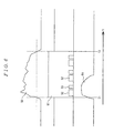
- FIG. 6 shows a relationship between the power control operation and communication packets in the wireless communication device according to the present invention.
- a waveform 54 of rotational energy generated by the energy generator 22 rises as shown.
- a voltage waveform 50 provided by the power generating coil 1 and rectified is smoothed and made constant by the power supply circuit 6 to produce a voltage waveform 51.
- the wireless control circuit 5 starts to drive at the time T1 and provides some indication through the indicator 4.
- transmission data is provided and very weak waves are transmitted through a transmission packet 52.
- an ACK (acknowledge) packet from the receiver end is sent out and it is received. In this example, these operations are repeated three times. Even if the energy supply from the energy generator 22 is stopped, the circuit can be driven by the time T2.
- the period between T1 to T2 can be approximately 5 to 10 seconds in the case of the spring 40 and thus, the wireless circuit 7 can be driven satisfactorily during this period. If something in place of the spring or rotational weight described above is not limited in shape and size, this period can be further extended.
- a wireless communication device having the receiving feature only cannot detect a timing of wave arrival but if data transmission is performed once every 5 to 10 seconds as described above, the date can be received at any time by using rotational energy generated by a spring or the like.
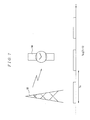
- FIG. 7 shows an application to which the wireless communication device according to the present invention is applied.
- a transmitting station 55 sends out time correction information.
- the transmitting station can be replaced by a mobile telephone, a personal computer, or the like.
- correction data is sent out at intervals Ts. If the interval Ts has a length shorter than the period between T1 to T2, the receiver end can receive a signal without knowledge of its arrival timing. Although it may depend on what packet to be passed therebetween during the power supply, at least one packet can be passed and the time can be corrected if Ts has a length shorter than the period between T1 and T2.
- FIGS. 8A and 8B show a second application to which the wireless communication device according to the present invention is applied.
- the present invention is incorporated in a personal computer and a mouse.
- the mouse 64 performs a wireless data communication with a wireless communication device 63 built in the personal computer 62.
- the power supply for the device 62 may be a commercial power supply or a solar battery.
- FIG. 8A shows an underside of the mouse, and the movement of a ball 69 in the mouse 64 is transferred to a roller 65 and relative coordinates are obtained from the number of revolutions to display a pointer on a display 60.
- the rotation of the roller 65 is connected to an electric power generation device 67 through a shaft 66 according to the present invention.
- the electric power generation device 67 is equivalent to that of FIG. 3 except that the energy generator 22 and the knob 20 are removed and as the mouse moves, the roller 65 rotates for power generation.
- the mouse generates transmission data when the mouse moves or when the mouse remains at rest with the click button pressed. While the mouse remains at rest, electric power can be generated by pressing the click button while a button 71 is held down.
- Another electric power generation device 72 can generate electric power by means of a mechanism for converting a pressure into rotational energy, for example, an attached mechanism using a gear or spring repulsion. Generated electric power will be transferred to the wireless control circuit 5 over a cable 68 and then radiated from the wireless circuit 7 with an antenna (not shown) . The receiving operation can be performed in a similar manner through the process described above with reference to FIG. 6.
- FIG. 9 shows a third application to which the wireless communication device according to the present invention is applied.
- the present invention is incorporated in a keyless entry system which may be one of suitable applications.
- An electronic lock 79 contains a wireless communication device 80 according to the present invention. Also, it has operation buttons 77, 78. In addition, a check lamp 81 of LED is provided to verify a transmission. A wave including transmission data provided by the electronic lock 79 drives a door lock mechanism 75 formed in an automobile door 73 through a wireless communication equipment 76 installed in an automobile for lock and unlock operations.
- the door lock mechanism 75 When the door 73 is in the locked state and a door knob 74 is pulled up within a predetermined period of time after the wireless communication equipment 76 has received a wave transmitted by the electronic lock 79, the door lock mechanism 75 will release the door lock in response to a signal from a switch which operates in coordination therewith. On the contrary, when the door 73 is in the unlocked state, the door lock mechanism 75 will lock the door in response to the reception of such a wave.
- Transmission data partly differs according to whether it is intended for locking or unlocking, which is determined on the receiver end.
- the wireless communication equipment 76 determines the state of the door 73 according to the data and transmits a signal to inform that the operation completes successfully.
- the electronic lock 79 receives the signal and turns on the check lamp 81. Since the check lamp 81 is used to verify the function when the device is ready to supply electric power, when the transmitting operation is performed, or when the receiving operation completes successfully, a plurality of check lamps or different colors of check lamps may be provided.
- the present invention is not limited to them and it can have similar effects to those of the above-described embodiments when it applies to any vibratory location, for example, in a belt, a hat, a hair band, a supporter, or some other wearable equipment with a band, fastener tape, or other fastening means as well as to a beeper, an electronic notepad, a PDA, a mobile telephone bag, or some other portable equipment .
- the wireless communication device since the wireless communication device according to the present invention uses very weak waves for which no license is required by the Radio Law in Japan, it can be implemented as a low-power system.
- the present invention can provide an eco-friendly waste-free wireless communication device by incorporating an electric power generation system which operates on natural energy rather than batteries. Moreover, if vibrational or rotational energy is converted by a flywheel into inertial energy and then stored, power generation can be continued for a period of time and thus, such wireless communication devices can perform two-way communications with each other.
- Any application to which the present invention is applied can take in natural energy without making a user aware of it. Therefore, the application compares favorably with conventional devices using battery in terms of usability.
Landscapes
- Engineering & Computer Science (AREA)
- Power Engineering (AREA)
- Mobile Radio Communication Systems (AREA)
- Transceivers (AREA)
- Near-Field Transmission Systems (AREA)
- Charge And Discharge Circuits For Batteries Or The Like (AREA)
- Electric Clocks (AREA)
- Electromechanical Clocks (AREA)
Abstract
Description
Claims (12)
- A wireless communication device, comprising:wherein said communication means performs a communication during the supply of electric power generated by said small electric power generation device.a small electric power generation device;signal generation means for generating a control signal or data signal to perform a wireless communication;communication means for transmitting/receiving the control signal or data signal generated by said signal generation means; andcontrol means for controlling said signal generation means and said communication means,in which said signal generation means and said communication means are driven by electric power generated by said small electric power generation device under the control of said control means,
- The wireless communication device according to claim 1,
wherein display means is provided to indicate that the wireless communication device is capable of performing a communication while said electric power generation device continuously generates electric power. - The wireless communication device according to claim 2,
wherein said small electric power generation device is an electric power generation device comprising:a rotational weight with an eccentric center of gravity; an electromagnetic transducer for generating electric power through the rotation of said rotational weight; and a mechanism for converting rotational energy into inertial energy. - The wireless communication device according to claim 3,
wherein said mechanism is a flywheel. - The wireless communication device according to claim 2,
wherein said small electric power generation device is an electric power generation device comprising:a mechanism for storing elastic energy from an elastic element; and a mechanism for converting the elastic energy into rotational energy and then inertial energy. - The wireless communication device according to claims 4 to 5,
wherein said small electric power generation device generates electric power by taking advantage of said inertial energy. - The wireless communication device according to claim 6,
wherein said wireless communication device performs a transmission and reception while said rotational energy and inertial energy are generated. - The wireless communication device according to claim 7,
wherein said wireless communication device is a wireless communication device built in an electronic lock and a wireless communication device mounted on an automobile, which perform a communication therebetween. - The wireless communication device according to claim 7,
wherein said wireless communication device is a wireless communication device built in a mouse pointer, which performs a communication with a computer. - The wireless communication device according to claim 9,
wherein said wireless communication device uses very weak waves. - The wireless communication device according to claim 7,
wherein said wireless communication device is a wireless communication device built in an electronic wristwatch, which performs a communication with a wireless base station. - The wireless communication device according to claim 11,
wherein said electronic wristwatch corrects the time in response to said data signal.
Applications Claiming Priority (2)
| Application Number | Priority Date | Filing Date | Title |
|---|---|---|---|
| JP2000309257A JP2002118480A (en) | 2000-10-10 | 2000-10-10 | Radio communication equipment |
| JP2000309257 | 2000-10-10 |
Publications (2)
| Publication Number | Publication Date |
|---|---|
| EP1198051A2 true EP1198051A2 (en) | 2002-04-17 |
| EP1198051A3 EP1198051A3 (en) | 2002-06-26 |
Family
ID=18789454
Family Applications (1)
| Application Number | Title | Priority Date | Filing Date |
|---|---|---|---|
| EP01123886A Withdrawn EP1198051A3 (en) | 2000-10-10 | 2001-10-05 | Power generation mechanism for wireless communication devices |
Country Status (5)
| Country | Link |
|---|---|
| US (1) | US20020042292A1 (en) |
| EP (1) | EP1198051A3 (en) |
| JP (1) | JP2002118480A (en) |
| CN (1) | CN1348257A (en) |
| TW (1) | TW530469B (en) |
Cited By (3)
| Publication number | Priority date | Publication date | Assignee | Title |
|---|---|---|---|---|
| GB2403871A (en) * | 2003-07-09 | 2005-01-12 | David Moss | Wind-up mobile phone |
| DE102004045134B4 (en) * | 2004-09-17 | 2007-08-02 | Reinhard Prigge | Computer mouse and computer system |
| CN107808473A (en) * | 2016-09-09 | 2018-03-16 | 比亚迪股份有限公司 | Remind transmitter and alarm set |
Families Citing this family (37)
| Publication number | Priority date | Publication date | Assignee | Title |
|---|---|---|---|---|
| JP2004251003A (en) * | 2003-02-20 | 2004-09-09 | Fuji Heavy Ind Ltd | Door lock control device |
| JP3828892B2 (en) * | 2003-03-19 | 2006-10-04 | 日本電波工業株式会社 | High frequency radio |
| US20060238328A1 (en) * | 2003-05-02 | 2006-10-26 | Siemens Aktiengesellschaft | Method for call billing communication connections between communication terminals in separate, packet-switched communication networks |
| JP2007017278A (en) * | 2005-07-07 | 2007-01-25 | Tokai Rika Co Ltd | Portable watch having electronic key function |
| WO2009020757A1 (en) * | 2007-08-05 | 2009-02-12 | Masco Corporation | Door notification system |
| US7844305B2 (en) * | 2007-10-19 | 2010-11-30 | Motorola, Inc. | Method and apparatus for generating power in a mobile communication device |
| JP5137527B2 (en) * | 2007-10-26 | 2013-02-06 | 株式会社エヌ・ティ・ティ・ドコモ | mobile phone |
| US9454297B2 (en) * | 2009-06-12 | 2016-09-27 | Steelseries Aps | Navigation device and methods thereof |
| US8477425B2 (en) | 2010-02-28 | 2013-07-02 | Osterhout Group, Inc. | See-through near-eye display glasses including a partially reflective, partially transmitting optical element |
| US20150309316A1 (en) | 2011-04-06 | 2015-10-29 | Microsoft Technology Licensing, Llc | Ar glasses with predictive control of external device based on event input |
| US9223134B2 (en) | 2010-02-28 | 2015-12-29 | Microsoft Technology Licensing, Llc | Optical imperfections in a light transmissive illumination system for see-through near-eye display glasses |
| WO2011106797A1 (en) | 2010-02-28 | 2011-09-01 | Osterhout Group, Inc. | Projection triggering through an external marker in an augmented reality eyepiece |
| US10180572B2 (en) | 2010-02-28 | 2019-01-15 | Microsoft Technology Licensing, Llc | AR glasses with event and user action control of external applications |
| US8472120B2 (en) | 2010-02-28 | 2013-06-25 | Osterhout Group, Inc. | See-through near-eye display glasses with a small scale image source |
| US8488246B2 (en) | 2010-02-28 | 2013-07-16 | Osterhout Group, Inc. | See-through near-eye display glasses including a curved polarizing film in the image source, a partially reflective, partially transmitting optical element and an optically flat film |
| US9759917B2 (en) | 2010-02-28 | 2017-09-12 | Microsoft Technology Licensing, Llc | AR glasses with event and sensor triggered AR eyepiece interface to external devices |
| US9182596B2 (en) | 2010-02-28 | 2015-11-10 | Microsoft Technology Licensing, Llc | See-through near-eye display glasses with the optical assembly including absorptive polarizers or anti-reflective coatings to reduce stray light |
| US9129295B2 (en) | 2010-02-28 | 2015-09-08 | Microsoft Technology Licensing, Llc | See-through near-eye display glasses with a fast response photochromic film system for quick transition from dark to clear |
| US9341843B2 (en) | 2010-02-28 | 2016-05-17 | Microsoft Technology Licensing, Llc | See-through near-eye display glasses with a small scale image source |
| US9091851B2 (en) | 2010-02-28 | 2015-07-28 | Microsoft Technology Licensing, Llc | Light control in head mounted displays |
| US9134534B2 (en) | 2010-02-28 | 2015-09-15 | Microsoft Technology Licensing, Llc | See-through near-eye display glasses including a modular image source |
| US9097891B2 (en) | 2010-02-28 | 2015-08-04 | Microsoft Technology Licensing, Llc | See-through near-eye display glasses including an auto-brightness control for the display brightness based on the brightness in the environment |
| US9097890B2 (en) | 2010-02-28 | 2015-08-04 | Microsoft Technology Licensing, Llc | Grating in a light transmissive illumination system for see-through near-eye display glasses |
| US20120249797A1 (en) | 2010-02-28 | 2012-10-04 | Osterhout Group, Inc. | Head-worn adaptive display |
| US9128281B2 (en) | 2010-09-14 | 2015-09-08 | Microsoft Technology Licensing, Llc | Eyepiece with uniformly illuminated reflective display |
| US8482859B2 (en) | 2010-02-28 | 2013-07-09 | Osterhout Group, Inc. | See-through near-eye display glasses wherein image light is transmitted to and reflected from an optically flat film |
| US9229227B2 (en) | 2010-02-28 | 2016-01-05 | Microsoft Technology Licensing, Llc | See-through near-eye display glasses with a light transmissive wedge shaped illumination system |
| US9285589B2 (en) | 2010-02-28 | 2016-03-15 | Microsoft Technology Licensing, Llc | AR glasses with event and sensor triggered control of AR eyepiece applications |
| US8467133B2 (en) | 2010-02-28 | 2013-06-18 | Osterhout Group, Inc. | See-through display with an optical assembly including a wedge-shaped illumination system |
| US9366862B2 (en) | 2010-02-28 | 2016-06-14 | Microsoft Technology Licensing, Llc | System and method for delivering content to a group of see-through near eye display eyepieces |
| US8184983B1 (en) | 2010-11-12 | 2012-05-22 | Google Inc. | Wireless directional identification and subsequent communication between wearable electronic devices |
| US8430310B1 (en) | 2011-05-24 | 2013-04-30 | Google Inc. | Wireless directional identification and verification using wearable electronic devices |
| JP5704016B2 (en) | 2011-08-04 | 2015-04-22 | ソニー株式会社 | Wireless communication apparatus and electronic device |
| DE102013206955A1 (en) * | 2013-04-17 | 2014-11-06 | Würth Elektronik eiSos Gmbh & Co. KG | communicator |
| CN106354284A (en) * | 2016-11-04 | 2017-01-25 | 长春中际互频科技有限公司 | Wireless battery-free mouse assembly |
| BR112019009438B1 (en) * | 2016-11-16 | 2024-02-06 | Dow Global Technologies Llc | COMPOSITION AND CABLE |
| JP2019201535A (en) * | 2018-05-17 | 2019-11-21 | 長司 古川 | System of generating electricity while maintaining constant number of revolution of flywheel |
Family Cites Families (8)
| Publication number | Priority date | Publication date | Assignee | Title |
|---|---|---|---|---|
| US4928098A (en) * | 1984-03-30 | 1990-05-22 | Siemens Aktiengesellschaft | Method for code protection using an electronic key |
| JPH04340118A (en) * | 1990-06-05 | 1992-11-26 | Seiko Epson Corp | Computer |
| GB9124506D0 (en) * | 1991-11-19 | 1992-01-08 | Baylis Trevor G | Improvements in or relating to electrical devices |
| GB9523158D0 (en) * | 1995-11-10 | 1996-01-17 | Jeffs Robert W | A radio transceiver |
| US5659611A (en) * | 1996-05-17 | 1997-08-19 | Lucent Technologies Inc. | Wrist telephone |
| DE19721286C1 (en) * | 1997-05-21 | 1998-09-17 | Siemens Ag | Initialising motor vehicle anti-theft protection system with several portable electronic keys |
| KR100243159B1 (en) * | 1997-12-01 | 2000-02-01 | 윤종용 | Remote controller united wireless mouse |
| US6624742B1 (en) * | 2000-06-24 | 2003-09-23 | Motorola, Inc. | Wireless intelligent real estate sign and electronic lock box |
-
2000
- 2000-10-10 JP JP2000309257A patent/JP2002118480A/en not_active Withdrawn
-
2001
- 2001-10-05 US US09/970,764 patent/US20020042292A1/en not_active Abandoned
- 2001-10-05 EP EP01123886A patent/EP1198051A3/en not_active Withdrawn
- 2001-10-08 TW TW090124848A patent/TW530469B/en not_active IP Right Cessation
- 2001-10-10 CN CN01135490A patent/CN1348257A/en active Pending
Cited By (3)
| Publication number | Priority date | Publication date | Assignee | Title |
|---|---|---|---|---|
| GB2403871A (en) * | 2003-07-09 | 2005-01-12 | David Moss | Wind-up mobile phone |
| DE102004045134B4 (en) * | 2004-09-17 | 2007-08-02 | Reinhard Prigge | Computer mouse and computer system |
| CN107808473A (en) * | 2016-09-09 | 2018-03-16 | 比亚迪股份有限公司 | Remind transmitter and alarm set |
Also Published As
| Publication number | Publication date |
|---|---|
| JP2002118480A (en) | 2002-04-19 |
| CN1348257A (en) | 2002-05-08 |
| TW530469B (en) | 2003-05-01 |
| US20020042292A1 (en) | 2002-04-11 |
| EP1198051A3 (en) | 2002-06-26 |
Similar Documents
| Publication | Publication Date | Title |
|---|---|---|
| EP1198051A2 (en) | Power generation mechanism for wireless communication devices | |
| AU765295B2 (en) | Sound communication system between a portable unit and a communication terminal | |
| US6525996B1 (en) | Power feeding apparatus, power receiving apparatus, power transfer system, power transfer method, portable apparatus, and timepiece | |
| US7667657B2 (en) | Information processing apparatus | |
| US6996154B2 (en) | Low power dual protocol transceiver | |
| JP2004003161A (en) | Electronic key system | |
| JP2005299305A (en) | Portable machine, in-vehicle machine and keyless entry device | |
| AU2001284689A1 (en) | Low power dual protocol transceiver | |
| JP2001519131A (en) | Device for controlling the operation state of electronic equipment | |
| US6882268B2 (en) | Method for keyless unlocking of an access door to a closed space | |
| JP2003309490A (en) | Rfid device | |
| JPH08241383A (en) | Contactless IC card, contactless IC card system including the same, and data transmission method thereof | |
| CN101583203A (en) | Remote control device and remote control method for mobile phone | |
| CN103971439A (en) | Passive intelligent lock system based on restricted interaction | |
| JPH0325832B2 (en) | ||
| JPH09298486A (en) | Non-contact data transmission / reception method and device | |
| JPH10205186A (en) | Transmitter | |
| JPH10313933A (en) | Power generation device for portable electronic device and portable electronic device provided with the power generation device | |
| JPH11210287A (en) | Radio wave key system | |
| CN214195887U (en) | A self-generating car key | |
| JPH1159332A (en) | Wireless device controller | |
| JP3624009B2 (en) | Power supply circuit | |
| JPH0918381A (en) | RFID system | |
| JPH0628531A (en) | Signal generation device | |
| JPH10108266A (en) | Vibration alarm device |
Legal Events
| Date | Code | Title | Description |
|---|---|---|---|
| PUAI | Public reference made under article 153(3) epc to a published international application that has entered the european phase |
Free format text: ORIGINAL CODE: 0009012 |
|
| AK | Designated contracting states |
Kind code of ref document: A2 Designated state(s): AT BE CH CY DE DK ES FI FR GB GR IE IT LI LU MC NL PT SE TR |
|
| AX | Request for extension of the european patent |
Free format text: AL;LT;LV;MK;RO;SI |
|
| PUAL | Search report despatched |
Free format text: ORIGINAL CODE: 0009013 |
|
| AK | Designated contracting states |
Kind code of ref document: A3 Designated state(s): AT BE CH CY DE DK ES FI FR GB GR IE IT LI LU MC NL PT SE TR |
|
| AX | Request for extension of the european patent |
Free format text: AL;LT;LV;MK;RO;SI |
|
| RIC1 | Information provided on ipc code assigned before grant |
Free format text: 7H 02K 7/02 A, 7H 02K 7/18 B, 7G 04C 10/00 B |
|
| 17P | Request for examination filed |
Effective date: 20021121 |
|
| AKX | Designation fees paid |
Designated state(s): AT BE CH CY DE DK ES FI FR GB GR IE IT LI LU MC NL PT SE TR |
|
| 17Q | First examination report despatched |
Effective date: 20030311 |
|
| STAA | Information on the status of an ep patent application or granted ep patent |
Free format text: STATUS: THE APPLICATION IS DEEMED TO BE WITHDRAWN |
|
| 18D | Application deemed to be withdrawn |
Effective date: 20040316 |