EP1197821A2 - Acceleration/deceleration method - Google Patents
Acceleration/deceleration method Download PDFInfo
- Publication number
- EP1197821A2 EP1197821A2 EP01308753A EP01308753A EP1197821A2 EP 1197821 A2 EP1197821 A2 EP 1197821A2 EP 01308753 A EP01308753 A EP 01308753A EP 01308753 A EP01308753 A EP 01308753A EP 1197821 A2 EP1197821 A2 EP 1197821A2
- Authority
- EP
- European Patent Office
- Prior art keywords
- axis
- velocity
- acceleration
- deceleration
- follower
- Prior art date
- Legal status (The legal status is an assumption and is not a legal conclusion. Google has not performed a legal analysis and makes no representation as to the accuracy of the status listed.)
- Granted
Links
Images






Classifications
-
- G—PHYSICS
- G05—CONTROLLING; REGULATING
- G05B—CONTROL OR REGULATING SYSTEMS IN GENERAL; FUNCTIONAL ELEMENTS OF SUCH SYSTEMS; MONITORING OR TESTING ARRANGEMENTS FOR SUCH SYSTEMS OR ELEMENTS
- G05B19/00—Program-control systems
- G05B19/02—Program-control systems electric
- G05B19/18—Numerical control [NC], i.e. automatically operating machines, in particular machine tools, e.g. in a manufacturing environment, so as to execute positioning, movement or co-ordinated operations by means of program data in numerical form
- G05B19/416—Numerical control [NC], i.e. automatically operating machines, in particular machine tools, e.g. in a manufacturing environment, so as to execute positioning, movement or co-ordinated operations by means of program data in numerical form characterised by control of velocity, acceleration or deceleration
Definitions
- the present invention relates to an acceleration/deceleration method for controlling one movable object driven by one axis to pursue another movable object driven by another axis in an industrial machine such as a wrapping machine and a machine tool.
- a follower axis (which drives a movable object to pursue another movable object driven by an objective axis) is accelerated/decelerated so that only the velocity of the follower axis is made equal to the velocity of the objective axis.
- a velocity difference Ve Ve therebetween
- a motion of the follower axis X is delayed by an amount in the case where an acceleration/deceleration control (a linear acceleration/deceleration control in this example) is performed as indicated by the continuous line in comparison with the case where no acceleration/deceleration control is performed as indicated by the broken line to produce a positional displacement between the follower axis X and the objective axis Y.
- an acceleration/deceleration control a linear acceleration/deceleration control in this example
- the velocity Vx of the follower axis X reaches the target velocity Vy of the objective axis Y at a time te by the linear acceleration/deceleration control.
- the position of the follower axis X is displaced with respect to the position of the objective axis Y to cause a positional displacement between the positions of the two axes although the velocity Vx of the follower axis X is made coincide with the velocity Vy of the objective axis Y.
- An object of the present invention is to provide an acceleration/deceleration method capable of controlling a follower axis to pursue an objective axis so that the velocity and also the position of the follower axis coincide with the velocity and the position of the objective axis respectively.
- the acceleration/deceleration method comprises the steps of obtaining a positional difference between positions of an objective axis and a follower axis and a velocity difference between velocities of the objective axis and the follower axis; and performing a predetermined acceleration/deceleration processing based on the positional difference and the velocity difference, so that the position and the velocity of the follower axis coincide with the position and the velocity of the objective axis, respectively.
- the acceleration/deceleration method comprises the steps of: obtaining the sum of the positional displacement between the follower axis and the objective axis from the start of an acceleration/deceleration, and an initial positional difference between the follower axis and the objective axis at the start of the acceleration/deceleration; and controlling the time period of the acceleration and the time period of the deceleration of the follower axis so that the sum of the positional displacement and the initial positional difference is made zero when the velocity of the follower axis coincides with the velocity of the objective axis.
- Conditions of an initial positional difference and an initial velocity difference between the objective axis and the follower axis may be sorted into a plurality of cases and the velocity of the follower axis may be obtained for each case. Further, the positional difference and the velocity difference between the follower axis and the objective axis may be used as dynamic conditions for obtaining the velocity of the follower axis in the acceleration/deceleration, and the acceleration/deceleration may be dynamically performed by determining velocity of the follower axis based on the dynamic condition.
- Different acceleration/deceleration values may be set for the acceleration of the follower axis with respect to the objective axis and for the deceleration of the follower axis with respect to the objective axis. Further, the velocity of the follower axis may be limited not to exceed a predetermined value.
- the acceleration/deceleration method comprises the steps of: obtaining a positional difference between the positions of the objective axis and the follower axis and a velocity difference between the velocities of the objective axis and the follower axis; setting acceleration/deceleration values for acceleration and deceleration of the follower axis; and starting acceleration/deceleration of the follower axis in response to an acceleration/deceleration start command, and controlling the follower axis so that the velocity of the follower axis pursues to coincide with the velocity of the objective axis through an acceleration process and a deceleration process with the set acceleration/deceleration value.
- a change-over from the acceleration process to the deceleration process or from the deceleration process to the acceleration process of the follower axis is determined based on the positional difference between the objective axis and the follower axis and a motion amount of the follower axis with respect to a motion amount of the objective axis from time of the change-over of the acceleration/deceleration to time when the velocity of the follower axis reaches the velocity of the objective axis.
- a constant velocity process where the follower axis is driven at a constant velocity may be interposed between the acceleration process and the deceleration process.
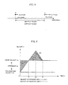
- FIG. 2 shows a principle of an acceleration/deceleration method of the present invention in which a velocity and a position of a follower axis X are controlled to pursue a velocity and a position of an objective axis Y, respectively.
- FIG. 2 variations of the veloctties of the follower axis X and the objective axis Y are shown with respect to time.
- Px and Py represent positions of the follower axis X and the objective axis Y, respectively; Vx and Vy represent velocities of the follower axis X and the objective axis Y, respectively; Px0 and Py0 represent initial positions of the follower axis X and the objective axis Y, respectively, and Vx0 and Vy0 represent initial velocities of the following axis X and the objective axis Y, respectively at a start of the acceleration/deceleration control.
- the velocity Vy is a target velocity of the follower axis X which has a constant value equal to the initial velocity Vy0.
- the acceleration/deceleration control is performed so that the velocity Vx of the follower axis X is equal to the velocity Vy of the objective axis Y with no positional difference.
- the follower axis X is continued to be accelerated and then a deceleration of the follower axis X is started with a deceleration value ⁇ (acceleration - ⁇ ) at time t2.
- the deceleration of the follower axis X is stopped when the velocity Vx reaches the target velocity Vy at time te with no positional difference.
- the acceleration value ⁇ is not necessarily a constant value.
- the follower axis X is continued to be accelerated after the velocity Vx reached the target velocity Vy and then turned over to the deceleration at the time t2 to reach the target velocity Vy again.
- the time t2 is determined so that an area S2, which corresponds to a motion amount of the follower axis X in excess of a motion amount of the objective axis Y while the velocity Vx exceeds the target velocity Vy, is equal to the area S 1 which corresponds to the positional difference.
- the velocity Vx and also position Px of the follower axis X coincide with the velocity Vy and position Py of the objective axis Y, respectively, after the time te.
- FIG. 3 shows another embodiment in which an acceleration value (inclination) ⁇ for the accelerating motion is set different from a deceleration value ⁇ for the decelerating motion of the follower axis X.
- the follower axis X is accelerated with the acceleration value ⁇ until the time t2 and decelerated with the deceleration ⁇ until the velocity Vx reaches the target velocity Vy, so that the follower axis X moves at the constant velocity same as the target velocity Vy after reaching the target velocity Vy again.
- the time t2 is determined so that the area S2 corresponding to the motion amount after the velocity Vx exceeds the target velocity Vy is equal to the area S1 corresponding to the motion amount before the velocity Vx reaches the target velocity Vy, to make the position and the speed of the follower axis X coincides with the position and the speed of the objective axis Y, respectively.
- FIG. 4 shows another embodiment of the pursuing acceleration/deceleration method in which the velocity Vx of the follower axis X in the acceleration/deceleration is clamped or limited to be not higher than a predetermined level.
- the motion amount of the objective axis Y is (Vy ⁇ t)
- the motion amount of the follower axis X is (Ve ⁇ t/2+Vx ⁇ t)
- the follower axis X is continued to be accelerated so that the velocity Vx of the follower axis X exceeds the target velocity Vy to make an excessive motion amount S2 to balance the displaced amount S1.
- the velocity Vx is clamped or limited not to exceed the predetermined value so that the constant velocity portion is formed as shown in FIG. 4.
- the distance S2 in moving at the velocity exceeding the velocity Vy of the objective axis Y is equal to the displacement S1.
- the position Px of the follower axis X is not displaced from the position Py of the objective axis Y after the velocity Vx coincides with the velocity Vy and the follower axis X moves with the objective axis Y at the same velocity and maintaining the relative position of the axes.
- the initial positional displacement can be canceled according to the present invention.
- the displacement between the follower axis X and the objective axis Y is made equal to the initial displacement dp0 at the start time of the acceleration/deceleration and the position Px of the follower axis X is behind the position Py of the objective axis Y by the distance dp0.
- the follower axis X is advanced with respect to the objective axis Y by the initial positional difference dp0. This is achieved by elongating the time period of the acceleration longer than the time period for making the area S2 equal to the area S1 to delay the time t2 at which the acceleration is changed over to the deceleration.
- the time t2 is determined so that the area S3 equal to the initial positional difference dp0 is formed, thereby the velocities and the positions of the follower axis X and the objective axis Y are made equal to each other and move in complete synchronism.
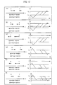
- the above described example is one of cases in which the position Px of the follower axis X and the position Py of the objective axis Y are leaving from each other. There are six cases (a)-(f) where the position Px and the position Py are leaving from each other, as shown in FIG. 11.
- the time of changing the accelerating motion over to the decelerating motion is delayed with respect to the time of switching in the case where die positional difference dp0 is "0" in accordance with the amount of the initial positional difference dp0, to thus cancel the initial positional difference dp0 and render the positions Px and Py and the velocities Vx and Vy of the follower axis X and the objective axis Y be equal to move in synchronism.
- FIG. 7 shows an example of the cases (2) in which the initial positional difference dp0 is negative and the initial velocity difference dv0 is positive.
- the objective axis Y and the follower axis X are both moving in the positive direction.
- the acceleration/deceleration processing is determined in dependence on values of the positional difference dp0 and the velocity difference dv0.
- FIG. 8 shows an acceleration/deceleration processing in the case where the positional difference dp0 is relatively large and the velocity difference dv0 is relatively small.
- the follower axis X is accelerated in the negative direction, i.e., decelerated and then accelerated in the positive direction at time t1 so that the velocity Vx reaches the velocity Vy of the objective axis Y at time te.
- the motion amount Sx of the follower axis X is expressed by the area indicated by the hatching slanted from left below to right up in FIG. 8.
- the positional difference (Sx- Sy) obtained by subtracting the motion amount Sx of the follower axis X from the motion amount Sy of the objective axis Y is expressed by the area indicated by the hatching slanted from the left up to the right below.
- the position Px and velocity Vx of the follower axis X are made equal to the position Py and velocity Vy of the objective axis Y, respectively, by making the distance (Sx- Sy) equal to the initial positional distance dp0. This is achieved by appropriately setting the time t1 at which the decelerating motion of the follower axis X is changed over to the accelerating motion.
- the follower axis X is accelerated with an appropriately determined acceleration value so that the velocity Vx reaches the target velocity Vy at time te.
- the acceleration value is determined so that the displaced amount (Sy - Sx) is equal to the initial positional difference dp0 between the follower axis X and the objective axis Y.
- the acceleration/deceleration processing is performed as shown in FIG. 10.
- the positional displacement obtained by subtracting the motion amount of the follower axis X from the motion amount of the objective axis Y from the start time "0" to the time t2 is expressed by the area S indicated by the hatching slanting from the left above to the right below.
- the positional displacement S1 is larger than the initial positional difference dp0, it means that the position Px of the follower axis X has been passed by the position Py of the objective axis Y when the velocity Vx of the follower axis X reaches the velocity Vy of the objective axis Y at the time t2.
- the position Px of the follower axis X is passed by the position Py of the objective axis Y at time t1.
- the follower axis X is continued to be accelerated to balance the positional difference produced after the position Px of the follower axis X is passed by the position Py of the objective axis Y.
- FIG. 13 schematically shows a control system for carrying out the acceleration/deceleration method of the present invention.
- a numerical controller is used as a controller in the control system and since configuration and function of the numerical controller are well known in the art, the following description will be made in summary.
- a numerical controller 10 comprises a processor, memories such as ROM and RAM, an input/output circuit and a communication interface.
- the numerical controller 10 controls two axis of a machine.
- the numerical controller 10 drivingly controls a servomotor Mx and a servomotor My by performing feedback controls of positions and velocities of respective axes using feedback signals from position/velocity detectors provided at the servomotors Mx and My or at movable parts driven by the servomotors Mx and My.
- a manual pulse generator 12 for generating pulses by manual operation by an operator is connected with the controller 10 and a pulse train is outputted of the manual pulse generator 12 in accordance with a speed of the manual operation with respect to a designated axis (Mx or My), and the designated servomotor is drivingly controlled by the controller 10 based on the pulse train from the manual pulse generator 12.
- the controller 10 further connected with another controller for controlling a machine or an apparatus via the communication interface and a communication line to output/input signals to/from another controller.
- FIG. 14 is a flowchart of processing for carrying out the pursuing acceleration/deceleration method of the present invention, to be executed by the processor of the controller 10 as shown in FIG. 13.
- the servomotor My drives the objective axis Y at the target velocity Vy and the servomotor Mx drives the follower axis X.
- the servomotor Mx is controller by the controller 10 according to the processing as shown in FIG. 14.
- the servomotor Mx is referred to as a follower axis servomotor and the servomotor My is referred to as an objective axis servomotor.
- the follower axis X is differently controlled in dependence on the conditions of the positions and velocities of the follower axis and the objective axis, and therefore the processing to be executed by the processor of the controller 10 in every predetermined processing period will be described with respect to the respective conditions.
- acceleration and "deceleration” used in the following description are defined.
- an acceleration in positive direction is referred to as “acceleration”
- an acceleration in negative direction is referred to as "deceleration”.
- the acceleration in negative direction is referred to as "acceleration” and the acceleration in positive direction is referred to as "deceleration”.
- FIG. 14 is the flowchart of the acceleration/deceleration processing to be executed by the processor of the controller 10.
- the objective axis Y is driven at the constant velocity Vy and when a pursuing command is issued for the follower axis X, the processor of the controller 10 starts the processing of FIG. 14 at the predetermined processing period.
- the positions and the velocities may be obtained on the basis of the feedback signals from the position/velocity detectors provided at the servomotors for respective axes.
- the positions and the velocities may be obtained by obtaining the position form a present position register for obtaining the present position by multiplying the motion amounts commanded at every processing period for respective axes, and the velocity may be obtained from the motion amounts commanded in the immediately preceding period (which represents the velocity since the motion amount in the predetermined processing period).
- Step A2 it is determined whether or not the position Px of the follower axis X does not exceed the position Py of the objective axis Y, or the velocity Vx of the follower axis X does not exceed the target velocity Vy of the objective axis Y, if the follower axis X is accelerated with the maximum value in the present processing period.
- This step corresponds to the above case I-(1). If either the position Px will not exceed the position Py or the velocity Vx will not exceed the velocity Vy, the follower axis X is accelerated with the maximum value. This processing is performed by outputting the motion amount obtained by adding the maximum acceleration value to the motion amount outputted in the immediately preceding period to accelerate the follower axis X.
- Step A4 the motion amount obtained by adding an amount corresponding to a difference between the position of the follower axis X and the position of the objective axis Y to the motion amount outputted in the immediately preceding period is outputted (Step A4).
- Step A5 it is determined whether or not the position Px of the follower axis X will pass by the position Py of the objective axis Y if the follower axis X is accelerated with the maximum value in the present processing period and is decelerated at the maximum value in the subsequent processing periods (Step A5). If it is determined that the position Px will not pass by the position Py if the follower axis X is fully accelerated at the present period and fully decelerated after the present period, the follower axis X is accelerated by outputting a motion amount obtained by adding the maximum acceleration amount to the immediately preceding motion amount (Step A10).
- the processing of Step A5 corresponds to the above case II-(1) and the processing between the time t1 and the time t2 in FIG. 6, as described later.
- Step A5 may be performed according to various methods. For example, assuming that the velocity Vx first becomes less than the velocity Vy by performing the full deceleration n-times from the present commanded velocity which is obtained by adding the maximum acceleration value to the commanded velocity in the immediately preceding processing period, the motion amount subjected to 1st deceleration processing is expressed as (Vx- ⁇ ) ⁇ T, the motion amount subjected to 2nd deceleration is expressed as (Vx-2 ⁇ ) ⁇ T, ⁇ , the motion amount subjected to n-th deceleration is expressed as (Vx-n ⁇ ) ⁇ T.
- the sum of the motion amounts subjected to the n-times full deceleration is expressed as follows;
- the sum ⁇ x of the motion amounts subjected to n-th deceleration, the motion amount from the start of the acceleration/deceleration processing to the present processing period and the motion amount subjected to the full acceleration in the present processing period are added up to obtain the motion amount of the follower axis X from the start of the acceleration/deceleration processing to the time when the position Px first becomes less than the position Py.
- the positional difference dp and the velocity difference dv between the objective axis Y and the follower axis X are used as dynamic conditions for obtaining the velocity Vx of the follower axis X for the present processing period in the acceleration/deceleration processing.
- the acceleration/deceleration is performed dynamically by determining the acceleration/deceleration value periodically based on the dynamic conditions.
- Step A6 It is determined whether or not the position Px will pass by the position Py if the velocity Vx is maintained in the present processing period and fully decelerated in the subsequent processing periods. This determination can be performed according to the method as described with respect to Step A5. If it is determined that the position Px will pass by the position Py if the velocity Vx is maintained in the present processing period and decelerated in the maximum value in the following processing periods, the velocity Vx is maintained or the follower axis X is accelerated with an adjusted acceleration amount.
- This processing is performed by obtaining a difference between the positional difference dp and the distance necessary for decelerating the velocity Vx to the target velocity Vy, and the obtained difference is divided by the number of processing periods necessary for decelerating the follower axis X to the target velocity Vy to determine the acceleration amount for one processing period.
- the follower axis X is accelerated by the determined acceleration amount (Step A11).
- Step A6 determines whether or not the sign of the velocity difference dv will reverse if the follower axis X is fully decelerated in the present processing period. If it is determined that the sign of the velocity difference dv will reverse, the follower axis X is decelerated to compensate the present positional difference dp (Step A12).
- the above processing in Steps A7 and A12 corresponds to the processing in the above case II-(3).
- Step A7 the procedure proceeds to Step A8 where it is determined whether or not the position Px will pass the position Py if the follower axis X is decelerated continuously from the present processing period. If the position Px will not pass the position Py, the follower axis X is decelerated by an adjusted deceleration amount (Step A13). This processing may be performed by obtaining a difference between the positional difference dp and the distance necessary for decelerating the velocity Vx to the target velocity Vy, and the obtained difference is divided by the number of processing periods necessary for decelerating the follower axis X to the target velocity Vy to determine the deceleration amount for one processing period. The follower axis X is decelerated with the determined deceleration amount. This processing corresponds to the processing in the above case II-(4).
- Step A9 If the result of determination in Step A8 is "Yes", the follower axis X is fully decelerated (Step A9). This processing corresponds to the processing in the above case II-(5).
- the acceleration/deceleration is performed so that the position and the velocity of the follower axis X are equal to the position and velocity of the objective axis Y, respectively, as described with reference to FIGS. 6-12.
- the processing of FIG. 14 is started when a command of pursuing acceleration/deceleration processing is inputted.
- Step A2 since the position Px will not pass by the position Py if the follower axis X is fully accelerated in the present processing period at the beginning of the procedure, the procedure proceeds to Step A3 where the follower axis X is fully accelerated by outputting a motion command obtained by adding the maximum acceleration amount to the motion command in the immediately preceding processing period.
- the processing of Steps A1-A3 is repeatedly executed until the velocity Vx exceeds the velocity Vy. These periods corresponds to the time period between t0 and t1 in FIG. 6.
- Step A5 it is determined whether or not the position Px will not reach the position Py if the follower axis X is fully accelerated in this processing period and fully decelerated continuously in the subsequent processing periods, as indicated by the dotted arrow in FIG. 6. In this example, it is determined that the position Px will not reach the position Py for a certain time after the velocity Vx exceeds the velocity Vy and the procedure proceeds Step A10 where the follower axis X is fully accelerated.
- the processing of Steps A1, A5 and A10 is repeatedly executed for the time period between the time t1 and the time t2.
- Step A6 it is determined whether or not the position Px will pass by the position Py if the velocity Vx is maintained in the present processing period and decelerated continuously in the subsequent processing periods. If it is determined that the position Px will not pass by the position Py, the acceleration amount to be added to the velocity command is adjusted or the velocity Vx is maintained at Step A11.
- Step A6 it is determined whether or not the sign of the velocity difference dv will reverse if the follower axis X is decelerated in the present processing period in Step A7. If the sign of the velocity difference will reverse, the deceleration amount to be subtracted from the present motion amount is adjusted at Step A12.
- Step A7 If the determination result in Step A7 is "No", it is determined whether or not the position Px will pass by the position Py if the follower axis X is decelerated in the present and the subsequent processing periods in Step A8.
- Step A5 and A6 are "Yes” since the acceleration amount has been adjusted so that the position Px will reach the position Py to make the positional difference dp be "0" if the follower axis X is fully decelerated continuously.
- the determination result in Step A7 is "No” until the velocity Vx come closer to the velocity Vy, and the procedure proceeds to Step A8 where it is determined whether or not the position Py will pass by the position Px if the follower axis X is fully decelerated in the present and the subsequent processing periods.
- the follower axis X is fully decelerated at Step A9 and if it is determined that the position Py will not pass by the position Px, the deceleration amount is adjusted at Step A13.
- Step A9 or Step A13 is performed in the time period between the time t2 and the time t3 in FIG. 6. Then, it is determined in Step A7 that the sign of the velocity difference dv will reverse if the follower axis is fully decelerated in the present processing period in the vicinity of the time te, and the procedure proceeds to Step A12 where the follower axis X is decelerated so that the velocity Vx equals to the velocity Vy and the positional difference dp is canceled. Thus, the positions and the velocities of the objective axis Y and the follower axis X are made equal.
- Step A4 the follower axis X is accelerated to cancel the positional difference dp.
- the positional difference has already canceled to be "0" except a normal error and thus the acceleration of the follower axis X is not performed. Consequently, the follower axis X moves in synchronism with the objective axis Y with their positions and also velocities respectively coincide with each other.
- Step A1 it is determined whether or not the position Px will pass by the position Py if the follower axis X is fully accelerated in this processing period and fully decelerated in the subsequent processing periods.
- the direction of acceleration is negative and the direction of deceleration is positive since the positional difference dp is negative according to the definition of these terms.
- Step A10 the follower axis X is fully accelerated (in the negative direction)
- the processing of Step A10 to fully accelerate the follower axis X is performed in the period from the time "0" to the time t1.
- Step A6 it is determined whether or not the position Px will pass by the position Py if the velocity Vx of the follower axis X is maintained in the present processing period and fully decelerated (in the negative direction) in the subsequent processing periods. If it is determined that the position Px will not pass by the position Py, the acceleration amount is adjusted at Step A11. If it is determined that the position Px will pass by the position Py, the procedure proceeds to Step A7.
- Step AS it is determined whether or not the position Px will pass by the position Py if the follower axis X is fully decelerated in the present and subsequent processing periods. If it is determined that the position Px will pass by the position Py, the follower axis X is fully decelerated (in the negative direction) at Step A9. If it is determined that the position Px will not pass by the position Py, the deceleration amount is adjusted at Step A13.
- Steps A5, A6 and A7 turn “Yes”, “Yes” and “No", respectively, to perform the full deceleration of the follower axis X.
- Step A12 When it is determined that the sign of the velocity difference dv will reverse if the follower axis X is fully decelerated in the present processing period at Step A7 in the vicinity of the time te, the procedure proceeds to Step A12 to decelerate the follower axis X to compensate the present positional difference.
- the positions and velocities of the follower axis X and the objective axis Y respectively coincide with each other.
- Step A6 it is determined that the position Px will pass the position Py if the velocity Vx is maintained in the present processing period and decelerated in the subsequent processing periods.
- the determination result in Step A7 is "No" to proceed Step A8.
- Step A8 it is determined that the position Px will not pass the position Py if the follower axis X is fully decelerated in the present and subsequent processing periods and the deceleration amount is adjusted at Step A13.
- Step A7 the procedure proceeds from Step A7 to Step A12 where the follower axis X is decelerated to compensate the present positional difference, so that the positions and velocities of the follower axis X and the objective axis Y respectively coincide with each other.
- Steps A1, A5-A8 is executed and it is determined that the position Px will pass by the position Py if the follower axis X is fully decelerated form the present processing period and the procedure proceeds to Step A9 where the follower axis X is fully decelerated.
- the procedure proceeds from Step A1 to Step A2 and the same procedure as shown in FIG. 6 is carried out.
- the acceleration of a constant value is adopted.
- the acceleration varying according to a linear equation, a quadratic equation, etc. may be adopted.
- FIG. 15 An example of application of the acceleration/deceleration method of the present invention is shown in FIG. 15.
- bottles 25 conveyed on an upper-stream conveyer 23 are aligned by an aligning mechanism 22 and placed on predetermined positions on a filling machine 20.
- the bottles 25 are filled with liquid on the filling machine 20 and the bottles 25 filled with liquid are transferred to a down-stream conveyer 21 and conveyed on the conveyer 21.
- the acceleration/deceleration method of the present invention is preferably adopted in this system.
- a driving axis of the filling machine 20 and the downstream conveyer 21 is controlled as the objective axis Y
- a driving axis of the upstream conveyer 23 and the aligning mechanism 22 is controlled as the follower axis X in accordance with the acceleration/deceleration method of the present invention, so that the positions and velocities of the aligning mechanism 22 and the filling mechanism 20 respectively coincide with each other.
- the follower axis X and also the objective axis Y are controlled by the controller 10.
- the objective axis Y is controlled by other controller which is connected with the controller 10 so that the controller 10 receives information on position and/or velocity of the objective axis Y and the controller 10 controls the follower axis X based on the received information.
- the velocity information may be obtained as a difference between the position information of this processing period and the position information of the immediately preceding processing period, and the position information may be obtained as the sum of the velocity information.
- the objective axis Y is controlled by the controller 10 and send information on the motion command (velocity information) obtained by the processing shown in FIG. 14 on the follower axis X to the other controller, so that the other controller controls the follower axis X on the basis of the received information on the motion command.
- the servomotor Mx may be controlled using the pulse train outputted from the manual pulse generator 12 treated as the position and velocity of the objective axis Y.
- the sum of the pulses generated by the pulse generator 12 is treated as the position of the objective axis Y and the velocity of generation of the pulses is treated as the velocity of the objective axis Y.
- the follower axis X may be controlled to catch up with any objective axis including a counter value of a timer or a pace maker treated as the position and velocity of the objective axis Y. Further, a position and a velocity of any axis detected by a detector may be used as the position and the velocity of the objective axis Y, and the follower axis X may be controlled based on the detected position and velocity of the objective axis Y.
- the motion of the follower axis X is controlled to be fully synchronized with the motion of the objective axis Y so that the positions and also the velocities of the follower axis and the objective axis respectively coincide with each other.
Landscapes
- Engineering & Computer Science (AREA)
- Human Computer Interaction (AREA)
- Manufacturing & Machinery (AREA)
- Physics & Mathematics (AREA)
- General Physics & Mathematics (AREA)
- Automation & Control Theory (AREA)
- Control Of Position Or Direction (AREA)
- Numerical Control (AREA)
Abstract
Description
→ accelerate the follower axis X by an amount for compensating the present positional difference dp
→ fully accelerate the follower axis X
→ maintain the velocity Vx or decelerate the follower axis X with an adjusted acceleration value
→ decelerate the follower axis X by an amount for compensating the present positional difference dp
→ maintain the velocity of the follower axis X or decelerate the follower axis X with an adjusted deceleration value
→ decelerate the follower axis at the maximum value

Claims (9)
- An accelerating/decelerating method for controlling position and velocity of a follower axis to pursue position and velocity of an objective axis, respectively, comprising the steps of:obtaining a positional difference between the positions of the objective axis and the follower axis and a velocity difference between the velocities of the objective axis and the follower axis; andperforming a predetermined acceleration/deceleration processing based on said positional difference and said velocity difference, so that the position and the velocity of the follower axis coincide with the position and the velocity of the objective axis, respectively.
- An acceleration/deceleration method for controlling position and velocity of a follower axis to pursue position and velocity of an objective axis, respectively, comprising the steps of:obtaining the sum of the positional displacement between the follower axis and the objective axis from the start of an acceleration/deceleration, and an initial positional difference between the follower axis and the objective axis at the start of the acceleration/deceleration; andcontrolling the time period of the acceleration and the time period of the deceleration of the follower axis so that said sum of the positional displacement and the initial positional difference is made zero when the velocity of the follower axis coincides with the velocity of the objective axis.
- An acceleration/deceleration method according to claim 1 or 2,
wherein conditions of an initial positional difference and an initial velocity difference between the objective axis and the follower axis are sorted into a plurality of cases and the velocity of the follower axis is obtained for each case. - An acceleration/deceleration method according to claim 1 or 2,
wherein the positional difference and the velocity difference between the follower axis and the objective axis are used as dynamic conditions for obtaining the velocity of the follower axis in the acceleration/deceleration, and the acceleration/deceleration is dynamically performed by determining velocity of the follower axis based on the dynamic condition. - An acceleration/deceleration method according to claim 4, wherein different acceleration/deceleration values are set for the acceleration of the follower axis with respect to the objective axis and for the deceleration of the follower axis with respect to the objective axis.
- An acceleration/deceleration method according to claim 4, wherein the velocity of the follower axis is limited so as not to exceed a predetermined value.
- An accelerating/decelerating method for controlling the velocity of a follower axis to pursue the velocity of an objective axis and the position of the follower axis to have a predetermined positional relation with respect to the position of the objective axis, said method comprising the steps of:wherein a change-over from the acceleration process to the deceleration process or from the deceleration process to the acceleration process of the follower axis is determined based on the positional difference between the objective axis and the follower axis and a motion amount of the follower axis with respect to a motion amount of the objective axis from time of the change-over of the acceleration/deceleration to time when the velocity of the follower axis reaches the velocity of the objective axis.obtaining a positional difference between the positions of the objective axis and the follower axis and a velocity difference between the velocities of the objective axis and the follower axis;setting acceleration/deceleration values for acceleration and deceleration of the follower axis; andstarting acceleration/deceleration of the follower axis in response to an acceleration/deceleration start command, and controlling the follower axis so that the velocity of the follower axis pursues to coincide with the velocity of the objective axis through an acceleration process and a deceleration process with the set acceleration/deceleration value,
- An acceleration/deceleration method according to claim 7, wherein a constant velocity process where the follower axis is driven at a constant velocity is interposed between the acceleration process and the deceleration process.
- An acceleration/deceleration method according to claim 7, wherein the acceleration value for acceleration of the follower axis and the deceleration value for deceleration of the follower axis are different.
Applications Claiming Priority (2)
| Application Number | Priority Date | Filing Date | Title |
|---|---|---|---|
| JP2000313200 | 2000-10-13 | ||
| JP2000313200A JP3453554B2 (en) | 2000-10-13 | 2000-10-13 | Acceleration / deceleration method |
Publications (3)
| Publication Number | Publication Date |
|---|---|
| EP1197821A2 true EP1197821A2 (en) | 2002-04-17 |
| EP1197821A3 EP1197821A3 (en) | 2004-01-21 |
| EP1197821B1 EP1197821B1 (en) | 2006-02-08 |
Family
ID=18792655
Family Applications (1)
| Application Number | Title | Priority Date | Filing Date |
|---|---|---|---|
| EP01308753A Expired - Lifetime EP1197821B1 (en) | 2000-10-13 | 2001-10-15 | Acceleration/deceleration method |
Country Status (4)
| Country | Link |
|---|---|
| US (1) | US6647353B2 (en) |
| EP (1) | EP1197821B1 (en) |
| JP (1) | JP3453554B2 (en) |
| DE (1) | DE60117113T2 (en) |
Cited By (1)
| Publication number | Priority date | Publication date | Assignee | Title |
|---|---|---|---|---|
| WO2009085422A1 (en) * | 2007-12-20 | 2009-07-09 | Ge Fanuc Intelligent Platforms, Inc. | Methods and systems for synchronizing a control signal of a slave follower with a master source |
Families Citing this family (5)
| Publication number | Priority date | Publication date | Assignee | Title |
|---|---|---|---|---|
| JP5803337B2 (en) * | 2011-06-28 | 2015-11-04 | オムロン株式会社 | Synchronization control device, synchronization control method, synchronization control program, and computer-readable recording medium recording the synchronization control program |
| JP6088581B2 (en) * | 2015-06-04 | 2017-03-01 | ファナック株式会社 | Machine tool control apparatus and control method for controlling synchronous operation of main shaft and feed shaft |
| JP6834853B2 (en) * | 2017-08-31 | 2021-02-24 | トヨタ自動車株式会社 | Vehicle control device |
| JP7177672B2 (en) * | 2018-11-26 | 2022-11-24 | オークマ株式会社 | Numerical controller |
| CN109656200B (en) * | 2018-12-10 | 2020-09-25 | 大族激光科技产业集团股份有限公司 | Flexible acceleration and deceleration control method and system for machine table |
Family Cites Families (24)
| Publication number | Priority date | Publication date | Assignee | Title |
|---|---|---|---|---|
| US4134681A (en) * | 1976-08-05 | 1979-01-16 | The United States Of America As Represented By The Secretary Of The Army | Method of determining relative orientation of physical systems |
| JPS58143981A (en) * | 1982-02-19 | 1983-08-26 | 株式会社日立製作所 | Control method for industrial robots |
| JPS58177287A (en) * | 1982-04-05 | 1983-10-17 | 株式会社日立製作所 | How to control the robot |
| US4774445A (en) * | 1986-11-20 | 1988-09-27 | Unimation, Inc. | Multiaxis robot control having capability for executing timed moves |
| US4829219A (en) * | 1986-11-20 | 1989-05-09 | Unimation Inc. | Multiaxis robot having improved motion control through variable acceleration/deceleration profiling |
| JPS63151289A (en) | 1986-12-16 | 1988-06-23 | Matsushita Electric Ind Co Ltd | Color signal processor |
| JP2566276B2 (en) | 1988-03-22 | 1996-12-25 | 三菱重工業株式会社 | Automatic allowable speed calculation NC device |
| JPH02256483A (en) * | 1989-03-29 | 1990-10-17 | Kobe Steel Ltd | Speed control device for industrial robot |
| JP2694669B2 (en) * | 1989-06-09 | 1997-12-24 | 株式会社日立製作所 | Robot motion control method |
| JPH03121748A (en) * | 1989-10-06 | 1991-05-23 | Fanuc Ltd | Spindle synchronous rotation control system |
| JP2815447B2 (en) | 1990-01-18 | 1998-10-27 | ファナック株式会社 | Speed clamp control method |
| KR930011004B1 (en) * | 1990-10-26 | 1993-11-19 | 삼성전자 주식회사 | Position Control Method of Robot |
| KR930007775B1 (en) * | 1990-12-28 | 1993-08-19 | 삼성전자 주식회사 | Linear interpolating method of robot |
| KR0160998B1 (en) * | 1992-09-18 | 1998-12-15 | 윤종용 | Robot trajectory planning method |
| JPH06138920A (en) | 1992-10-27 | 1994-05-20 | Yokogawa Electric Corp | Motion controller |
| JPH06332510A (en) * | 1993-03-24 | 1994-12-02 | Toyoda Mach Works Ltd | Numerical controller |
| JPH06337708A (en) * | 1993-05-27 | 1994-12-06 | Fanuc Ltd | System for acceleration and deceleration time constant control for robot |
| US5708342A (en) * | 1993-05-27 | 1998-01-13 | Fanuc Ltd. | Method of controlling acceleration/deceleration time constants for robot |
| US5434489A (en) * | 1993-07-30 | 1995-07-18 | Fanuc Robotics North America, Inc. | Method and system for path planning in cartesian space |
| JP3428804B2 (en) | 1995-03-20 | 2003-07-22 | 三菱電機株式会社 | Synchronous control method and synchronous control device in numerical controller |
| JPH09275695A (en) * | 1996-04-02 | 1997-10-21 | Minolta Co Ltd | Motor controller |
| JP3553741B2 (en) * | 1996-09-02 | 2004-08-11 | 三菱電機株式会社 | Numerical control device and spindle motor acceleration / deceleration control method for numerical control device |
| JP3325837B2 (en) * | 1998-07-09 | 2002-09-17 | 株式会社奥村組 | Control method of dam crane |
| JP2000142921A (en) * | 1998-11-11 | 2000-05-23 | Kito Corp | Method of controlling operation of stacker crane |
-
2000
- 2000-10-13 JP JP2000313200A patent/JP3453554B2/en not_active Expired - Fee Related
-
2001
- 2001-10-12 US US09/974,805 patent/US6647353B2/en not_active Expired - Lifetime
- 2001-10-15 EP EP01308753A patent/EP1197821B1/en not_active Expired - Lifetime
- 2001-10-15 DE DE60117113T patent/DE60117113T2/en not_active Expired - Lifetime
Cited By (2)
| Publication number | Priority date | Publication date | Assignee | Title |
|---|---|---|---|---|
| WO2009085422A1 (en) * | 2007-12-20 | 2009-07-09 | Ge Fanuc Intelligent Platforms, Inc. | Methods and systems for synchronizing a control signal of a slave follower with a master source |
| US7962240B2 (en) | 2007-12-20 | 2011-06-14 | Ge Intelligent Platforms, Inc. | Methods and systems for synchronizing a control signal of a slave follower with a master source |
Also Published As
| Publication number | Publication date |
|---|---|
| DE60117113T2 (en) | 2006-07-13 |
| EP1197821A3 (en) | 2004-01-21 |
| DE60117113D1 (en) | 2006-04-20 |
| US20020069029A1 (en) | 2002-06-06 |
| JP3453554B2 (en) | 2003-10-06 |
| US6647353B2 (en) | 2003-11-11 |
| EP1197821B1 (en) | 2006-02-08 |
| JP2002123319A (en) | 2002-04-26 |
Similar Documents
| Publication | Publication Date | Title |
|---|---|---|
| CN105278456B (en) | The numerical control device of gain function is controlled with switching position in the synch control | |
| EP0553356B1 (en) | Method and apparatus for prediction repetition control of servo motor | |
| JPS61157909A (en) | System for correcting route error of robot | |
| US12066807B2 (en) | Numerical control device, machine learning device, and numerical control method | |
| EP0089156B1 (en) | Method and apparatus for controlling acceleration and/or deceleration | |
| EP0187864A1 (en) | Acceleration/deceleration control system | |
| EP1197821B1 (en) | Acceleration/deceleration method | |
| US7759895B2 (en) | Numerical controller and synchronous control method using numerical controller | |
| EP0389708A3 (en) | Method of and apparatus for controlling velocity of industrial robot | |
| JPH0447415A (en) | Method and device for controlling linear motor in work carrying robot | |
| US20210311460A1 (en) | Numerical control device and numerical control method | |
| US10915093B2 (en) | Numerical controller | |
| US5740327A (en) | Method of and apparatus for robot tip trajectory control | |
| KR970022624A (en) | Clock Synchronous Movement Control Method and Device in Time Discrete Sampling System | |
| US20020103567A1 (en) | Method of and apparatus for synchronous control | |
| CN113858213B (en) | Robot dynamic track planning method for target synchronization | |
| JPH06138920A (en) | Motion controller | |
| EP4184265A1 (en) | System and method for managing automation systems with synchronous elements | |
| WO2003100536A1 (en) | Numerical value control device synchronization control method | |
| US12222700B2 (en) | Control device | |
| JPS59194207A (en) | Correction system for delay error of servo system in numerical control | |
| JP3242190B2 (en) | Numerical control unit | |
| JP6396389B2 (en) | Servo control device | |
| JP7725001B1 (en) | Control device and control method | |
| JPH04335409A (en) | Program tracking device |
Legal Events
| Date | Code | Title | Description |
|---|---|---|---|
| PUAI | Public reference made under article 153(3) epc to a published international application that has entered the european phase |
Free format text: ORIGINAL CODE: 0009012 |
|
| AK | Designated contracting states |
Kind code of ref document: A2 Designated state(s): AT BE CH CY DE DK ES FI FR GB GR IE IT LI LU MC NL PT SE TR |
|
| AX | Request for extension of the european patent |
Free format text: AL;LT;LV;MK;RO;SI |
|
| PUAL | Search report despatched |
Free format text: ORIGINAL CODE: 0009013 |
|
| AK | Designated contracting states |
Kind code of ref document: A3 Designated state(s): AT BE CH CY DE DK ES FI FR GB GR IE IT LI LU MC NL PT SE TR |
|
| AX | Request for extension of the european patent |
Extension state: AL LT LV MK RO SI |
|
| 17P | Request for examination filed |
Effective date: 20040714 |
|
| AKX | Designation fees paid |
Designated state(s): DE |
|
| 17Q | First examination report despatched |
Effective date: 20050113 |
|
| GRAP | Despatch of communication of intention to grant a patent |
Free format text: ORIGINAL CODE: EPIDOSNIGR1 |
|
| GRAS | Grant fee paid |
Free format text: ORIGINAL CODE: EPIDOSNIGR3 |
|
| GRAA | (expected) grant |
Free format text: ORIGINAL CODE: 0009210 |
|
| AK | Designated contracting states |
Kind code of ref document: B1 Designated state(s): DE |
|
| REF | Corresponds to: |
Ref document number: 60117113 Country of ref document: DE Date of ref document: 20060420 Kind code of ref document: P |
|
| PLBE | No opposition filed within time limit |
Free format text: ORIGINAL CODE: 0009261 |
|
| STAA | Information on the status of an ep patent application or granted ep patent |
Free format text: STATUS: NO OPPOSITION FILED WITHIN TIME LIMIT |
|
| 26N | No opposition filed |
Effective date: 20061109 |
|
| PGFP | Annual fee paid to national office [announced via postgrant information from national office to epo] |
Ref country code: DE Payment date: 20181002 Year of fee payment: 18 |
|
| REG | Reference to a national code |
Ref country code: DE Ref legal event code: R119 Ref document number: 60117113 Country of ref document: DE |
|
| PG25 | Lapsed in a contracting state [announced via postgrant information from national office to epo] |
Ref country code: DE Free format text: LAPSE BECAUSE OF NON-PAYMENT OF DUE FEES Effective date: 20200501 |