EP1197637A2 - Turbine - Google Patents
Turbine Download PDFInfo
- Publication number
- EP1197637A2 EP1197637A2 EP01308709A EP01308709A EP1197637A2 EP 1197637 A2 EP1197637 A2 EP 1197637A2 EP 01308709 A EP01308709 A EP 01308709A EP 01308709 A EP01308709 A EP 01308709A EP 1197637 A2 EP1197637 A2 EP 1197637A2
- Authority
- EP
- European Patent Office
- Prior art keywords
- vane
- actuator
- link
- vanes
- turbine
- Prior art date
- Legal status (The legal status is an assumption and is not a legal conclusion. Google has not performed a legal analysis and makes no representation as to the accuracy of the status listed.)
- Granted
Links
Images


Classifications
-
- F—MECHANICAL ENGINEERING; LIGHTING; HEATING; WEAPONS; BLASTING
- F01—MACHINES OR ENGINES IN GENERAL; ENGINE PLANTS IN GENERAL; STEAM ENGINES
- F01D—NON-POSITIVE DISPLACEMENT MACHINES OR ENGINES, e.g. STEAM TURBINES
- F01D17/00—Regulating or controlling by varying flow
- F01D17/10—Final actuators
- F01D17/12—Final actuators arranged in stator parts
- F01D17/14—Final actuators arranged in stator parts varying effective cross-sectional area of nozzles or guide conduits
- F01D17/16—Final actuators arranged in stator parts varying effective cross-sectional area of nozzles or guide conduits by means of nozzle vanes
- F01D17/165—Final actuators arranged in stator parts varying effective cross-sectional area of nozzles or guide conduits by means of nozzle vanes for radial flow, i.e. the vanes turning around axes which are essentially parallel to the rotor centre line
Definitions
- the present invention relates to a turbine, and in particular to a turbine which can be used in a turbocharger comprising a turbine stage and a compressor stage on a common shaft.
- the turbine stage comprises a turbine wheel, a housing (which may comprise several components) in which the wheel is mounted between an inlet and an outlet defined by the housing, and an array of vanes mounted in the inlet so as to direct gas towards the turbine wheel. It has been known for many years that advantages can be obtained if the turbine stage has a variable flow size, that is a variable inlet cross-section which can be controlled to optimise flow velocities despite variations in mass flow rates.
- One widely applied method of varying the flow size of a turbocharger turbine stage is to provide an array of movable vanes in the turbine inlet.
- Each vane can pivot about an axis extending across the inlet parallel to the turbocharger shaft and aligned with a point approximately half way along the vane length.
- a vane actuating mechanism is provided which is linked to each of the vanes and is displaceable in a manner which causes each of the vanes to move in unison, such a movement enabling the cross sectional area available for the incoming gas and the angle of approach of the gas to the turbine wheel to be controlled.
- Such arrangements are generally referred to as swing vane variable geometry turbochargers.
- each vane is mounted on a pivot axle, the axle projecting through a wall of the inlet and supporting outside the inlet a crank or lever.
- the crank of each vane is coupled to an actuator ring which extends around the turbocharger housing generally outside the inlet but adjacent the vane cranks.
- This actuator ring is generally referred to as a unison ring.
- the unison ring is coupled either directly to the vane cranks or by links which provide for relative movement between interconnected components.
- the links are pivotally connected to the vane cranks. Manufacturing considerations mean that there must be clearance at such interconnections and this clearance results in backlash in the mechanism and vibration of the interconnected parts.
- a turbine comprising a turbine wheel, a housing in which the wheel is mounted between an inlet and an outlet defined by the housing, a plurality of vanes rotatably mounted in the inlet, and an actuator which is displaceable relative to the vanes and is coupled to each vane such that displacement of the actuator causes the vanes to pivot, wherein each vane is coupled to the actuator by a respective flexible link arranged such that actuator displacement causes the links to flex.
- the flexibility of the links enables rotation of the vanes as a result of actuator displacement to be accommodated by flexing the links, enabling the use of connections between the links and the vanes which are not subject to backlash.
- a turbine comprising a turbine wheel, a housing in which the wheel is mounted between an inlet and an outlet defined by the housing, a plurality of vanes rotatably mounted in the inlet, and an actuator which is displaceable relative to the vanes and is coupled to each vane such that displacement of the actuator causes the vanes to pivot, each vane being coupled to the actuator by a respective flexible link arranged such that actuator displacement causes the links to flex, wherein each link has one end secured to the respective vane in a manner which prevents relative movement between the vane and said one end and an other end secured to the actuator in a manner which prevents relative movement between the actuator and said other end.
- Similar connections may be used at the ends of the links connected to the actuator.
- the links may be secured in position by any convenient means which prevents relative movement between the ends of the links and the vane and/or the actuator.
- the links may be secured by rivets or by being received in appropriate slots. As in such arrangements there is no rubbing and hence wear between the various components, long term reliability is enhanced.
- Each link preferably flexes in a direction lying in a plane plane perpendicular to the rotational axis of the respective vane.
- Each vane may be supported and axially connected to a crank, each vane crank being coupled to a respective link.
- the actuator may be defined by a ring extending around the housing adjacent to the vanes outside the inlet, the links extending between the actuator ring and the vane cranks.
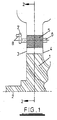
- the schematically illustrated conventional swing vane turbine comprises a turbine wheel 1 rotatable about an axis indicated by a line 2 within a housing having an inlet defined between housing walls 3 and 4. Exhaust gases flow into the inlet in a radially inwards direction to drive the turbine wheel.
- an annular array of vanes 5 each of which is formed with a respective integral axle 6 that projects through the inlet wall and one end of which defines a crank 7.
- An actuator (not shown) may be coupled to a pin 8 mounted on the crank 7 so as to control rotation of the vane 5 on the axle 6.
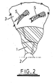
- Figure 2 shows two of the adjacent vanes, the vane being shown in full line in one position in which the available cross-section of the inlet is relatively large and in dotted lines in an alternative position in which the available cross-section of the inlet is relatively small.
- the positions of the vane cranks 7 are controlled by links (not shown) which are pivotally mounted on the pins 8. Given inevitable manufacturing tolerances there will be some clearance between the links and the pins 8. Accordingly, backlash in the vane position control mechanism is inevitable, such backlash increasing with wear.
- Each vane 5 is mounted between surfaces 3 and 4 which define opposite sides of a flow inlet into which exhaust gas is directed as indicated by arrow 9. Gas which flows past the vanes 5 is directed into the turbine wheel housing area as indicated by arrows 10, the gas flow velocity being optimised by appropriate positioning of the vanes 5.
- Each vane axle 6 extends through the housing wall to project through both the housing wall and a respective slot 11 provided in a unison ring 12. The ends of the axle supports crank 7. As is best seen in Figure 3, the unison ring in this embodiment is of u-shaped cross-section.
- Each crank 7 supports a circumferentially-extending arm 13 to which a flexible link 14 of spring material is secured by a rivet 15.
- the other end of the flexible link is secured to the unison ring by a further rivet 16.
- the unison ring is rotatable about an axis 17 which corresponds with the rotation axis of the turbine wheel (not shown).
- the angular position of the unison ring 12 about the axis 17 is controlled by movement of an input bracket 18 in the direction indicated by an arrow 19. Displacement of the unison ring 12 is accommodated by the slots 11 in the ring. Given the flexible nature of the links 14, as the unison ring is moved in the direction of arrow 19 each of the axles 6 is rotated in the anticlockwise direction of Figure 4. Rotation about the axle 6 is accommodated by flexing of the links 14. No relative movement occurs between either end of the links 14 and the components which the ends of those links are secured by rivets 15 and 16. Thus the system is not subject to backlash nor wear as a result of relative movement between interconnected components.
- the links 14 are secured in position by rivets 15 and 16.
- Other methods of attachment of the links to the unison ring and vane cranks 7 are however possible.
- the flexible links may be designed for direct connection between the unison ring and the respective vane axle.
- An example of such an embodiment is illustrated in Figure 5.
- the link 20 is formed in a generally "L" shape, the long portion of the link 20 being riveted to the unison ring by a rivet 21 and the short portion of the link 20 being riveted directly to a modified vane axle 22 by a rivet 23 (a cut-out 22a is formed in the end of the vane axle to accommodate the rivet connection).
- the detailed design of the L shaped link 20 could be controlled to ensure flexing is confined to a particular region of the link, for instance the long portion riveted to the unison ring, to minimise fatigue.
- a peg In order to control the position of the unison ring, a peg could be inserted in the u-shape slot in the bracket 18, displacement of the peg causing displacement of the unison ring. Such an arrangement would itself be prone to some backlash and it might be advantageous to link the peg or other input device to the unison ring by a flexible link similar to the flexible links used to interconnect the unison ring and vanes.
Landscapes
- Engineering & Computer Science (AREA)
- Mechanical Engineering (AREA)
- General Engineering & Computer Science (AREA)
- Control Of Turbines (AREA)
- Supercharger (AREA)
Abstract
Description
Claims (12)
- A turbine comprising a turbine wheel, a housing in which the wheel is mounted between an inlet and an outlet defined by the housing, a plurality of vanes rotatably mounted in the inlet, an actuator which is displaceable relative to the vanes and is coupled to each vane such that displacement of the actuator causes the vanes to pivot, wherein each vane is coupled to the actuator by a respective flexible link, each flexible link coupling a single vane to the actuator and being arranged such that actuator displacement causes the links to flex.
- A turbine according to claim 1, wherein each link has an end secured to the respective vane in manner which prevents relative movement between the vane and the end secured to the vane.
- A turbine according to claims 1 or 2, wherein each link has an end secured to the actuator in a manner which prevents relative movement between the actuator and the link end secured to the actuator.
- A turbine according to claim 2 or 3, wherein the link ends are secured by rivets.
- A turbine according to claim 2 or 3, wherein the link ends are inserted into and secured within slots.
- A turbine according to any preceding claim, wherein each vane is supported on an axle connected to a crank, each vane crank being coupled to a respective link.
- A turbine according to claim 6, wherein the actuator is defined by a ring extending around the housing adjacent to the vanes outside the inlet, the links extending between the actuator ring and the vane cranks.
- A turbine according to any one of claims 1 to 5, wherein each vane is supported on an axle and each link is directly coupled to a respective vane axle.
- A turbine according to claim 8, wherein each link is generally L shaped.
- A turbine according to any preceding claim, wherein each flexible link rotates in a direction lying in a plane substantially perpendicular to the pivot axis of the respective vane.
- A turbine comprising a turbine wheel, a housing in which the wheel is mounted between an inlet and an outlet defined by the housing, a plurality of vanes rotatably mounted in the inlet, and an actuator which is displaceable relative to the vanes and is coupled to each vane such that displacement of the actuator causes the vanes to pivot, each vane being coupled to the actuator by a respective flexible link arranged such that actuator displacement causes the links to flex, wherein each link has one end secured to the respective vane in a manner which prevents relative movement between the vane and said one end and an other end secured to the actuator in a manner which prevents relative movement between the actuator and said other end.
- A turbine according to claim 11, further comprising the features of any one of claims 4 to 11.
Applications Claiming Priority (2)
| Application Number | Priority Date | Filing Date | Title |
|---|---|---|---|
| GB0025244 | 2000-10-12 | ||
| GBGB0025244.5A GB0025244D0 (en) | 2000-10-12 | 2000-10-12 | Turbine |
Publications (3)
| Publication Number | Publication Date |
|---|---|
| EP1197637A2 true EP1197637A2 (en) | 2002-04-17 |
| EP1197637A3 EP1197637A3 (en) | 2004-05-26 |
| EP1197637B1 EP1197637B1 (en) | 2008-01-16 |
Family
ID=9901313
Family Applications (1)
| Application Number | Title | Priority Date | Filing Date |
|---|---|---|---|
| EP01308709A Expired - Lifetime EP1197637B1 (en) | 2000-10-12 | 2001-10-12 | Turbine |
Country Status (5)
| Country | Link |
|---|---|
| US (1) | US6779971B2 (en) |
| EP (1) | EP1197637B1 (en) |
| CN (1) | CN1330853C (en) |
| DE (1) | DE60132412T2 (en) |
| GB (1) | GB0025244D0 (en) |
Cited By (4)
| Publication number | Priority date | Publication date | Assignee | Title |
|---|---|---|---|---|
| WO2006053579A1 (en) * | 2004-11-16 | 2006-05-26 | Honeywell International Inc. | Variable nozzle turbocharger |
| US7628580B2 (en) | 2004-04-08 | 2009-12-08 | Holset Engineering Company, Limited | Variable geometry turbine |
| WO2010149725A1 (en) * | 2009-06-26 | 2010-12-29 | Snecma | Method and device for resetting the control of variable-geometry equipment for a turbomachine |
| WO2010149724A1 (en) * | 2009-06-26 | 2010-12-29 | Snecma | Device and method for positioning variable-geometry equipment for a turbomachine, using a relative-measurement jack |
Families Citing this family (23)
| Publication number | Priority date | Publication date | Assignee | Title |
|---|---|---|---|---|
| EP1394364B1 (en) * | 2002-08-26 | 2006-03-08 | BorgWarner Inc. | Turbocharger and annular guide conduit therefor |
| US7207176B2 (en) * | 2002-11-19 | 2007-04-24 | Cummins Inc. | Method of controlling the exhaust gas temperature for after-treatment systems on a diesel engine using a variable geometry turbine |
| US7150151B2 (en) * | 2002-11-19 | 2006-12-19 | Cummins Inc. | Method of controlling the exhaust gas temperature for after-treatment systems on a diesel engine using a variable geometry turbine |
| DE10316389B3 (en) * | 2003-04-10 | 2004-01-22 | Mtu Friedrichshafen Gmbh | Guide device for an exhaust gas turbocharger |
| US7280950B2 (en) * | 2004-01-22 | 2007-10-09 | Electro-Motive Diesel, Inc. | Locomotive diesel engine turbocharger and turbine stage constructed with turbine blade vibration suppression methodology |
| DE102004023282A1 (en) * | 2004-05-11 | 2005-12-01 | Volkswagen Ag | Exhaust-gas turbocharger for motor vehicle, has guide vane carrier with cascaded section having reduced outer diameter, which is smaller than inner diameter of radial inner surface of ring, such that section forms radial plain bearing |
| DE102004037082A1 (en) * | 2004-07-30 | 2006-03-23 | Volkswagen Ag | Exhaust gas turbocharger for internal combustion engine of especially motor vehicle has first slide surface formed on bearing housing and axially guides adjustment ring on side facing away from guide vane carrier |
| JP2006193287A (en) * | 2005-01-14 | 2006-07-27 | Pfu Ltd | Sheet feeding apparatus and jam detection method of the apparatus |
| DE102006048514B3 (en) * | 2005-12-01 | 2007-05-10 | Mtu Friedrichshafen Gmbh | Guidance device for VTG-exhaust gas turbocharger, has fixing element on side, which is turned away from blade lever, is designed as stopper for following spring element |
| US20100172745A1 (en) * | 2007-04-10 | 2010-07-08 | Elliott Company | Centrifugal compressor having adjustable inlet guide vanes |
| DE102008007670B4 (en) * | 2008-02-06 | 2021-01-07 | BMTS Technology GmbH & Co. KG | Control ring for VTG |
| US8393858B2 (en) * | 2009-03-13 | 2013-03-12 | Honeywell International Inc. | Turbine shroud support coupling assembly |
| CN102648334B (en) | 2009-10-06 | 2016-03-30 | 康明斯有限公司 | Variable-geometry turbine |
| BR112012007827A2 (en) | 2009-10-06 | 2016-03-08 | Cummins Ltd | variable geometry turbine. |
| EP2486243A2 (en) | 2009-10-06 | 2012-08-15 | Cummins Ltd | Variable geometry turbine |
| WO2011042700A2 (en) | 2009-10-06 | 2011-04-14 | Cummins Ltd | Variable geometry turbine |
| CN103046969B (en) * | 2013-01-09 | 2014-09-24 | 于魁江 | Novel pneumatic impeller |
| JP5807037B2 (en) * | 2013-05-16 | 2015-11-10 | 株式会社豊田自動織機 | Variable nozzle turbocharger |
| US9429033B2 (en) * | 2013-11-08 | 2016-08-30 | Honeywell International Inc. | Drive arrangement for a unison ring of a variable-vane assembly |
| US11092167B2 (en) * | 2018-08-28 | 2021-08-17 | Pratt & Whitney Canada Corp. | Variable vane actuating system |
| US11092032B2 (en) * | 2018-08-28 | 2021-08-17 | Pratt & Whitney Canada Corp. | Variable vane actuating system |
| US11371380B2 (en) | 2020-12-01 | 2022-06-28 | Pratt & Whitney Canada Corp. | Variable guide vane assembly and vane arms therefor |
| US11649734B1 (en) | 2022-04-28 | 2023-05-16 | Pratt & Whitney Canada Corp. | Variable guide vane control system |
Family Cites Families (48)
| Publication number | Priority date | Publication date | Assignee | Title |
|---|---|---|---|---|
| US2955744A (en) * | 1955-05-20 | 1960-10-11 | Gen Electric | Compressor |
| GB1063602A (en) * | 1966-01-10 | 1967-03-30 | Rolls Royce | Vane operating mechanism for a fluid flow machine |
| US3566916A (en) * | 1969-05-01 | 1971-03-02 | Ruskin Mfg Co | Inlet vane damper |
| US3719427A (en) * | 1971-03-22 | 1973-03-06 | Caterpillar Tractor Co | Variable area nozzle for turbines or compressors |
| DE2253030A1 (en) * | 1972-10-28 | 1974-05-09 | Sljusarew | DEVICE FOR BLADE ADJUSTMENT OF THE CONTROL UNIT OF A FLOW MACHINE |
| DE2333525C3 (en) * | 1973-07-02 | 1975-11-27 | Motoren- Und Turbinen-Union Friedrichshafen Gmbh, 7990 Friedrichshafen | Hydraulic guide vane adjustment device |
| GB1510629A (en) * | 1974-08-08 | 1978-05-10 | Penny Turbines Ltd N | Centrifugal compressor or centripetal turbine |
| GB1511723A (en) | 1975-05-01 | 1978-05-24 | Rolls Royce | Variable stator vane actuating mechanism |
| GB2042646B (en) * | 1979-02-20 | 1982-09-22 | Rolls Royce | Rotor blade tip clearance control for gas turbine engine |
| US4378960A (en) | 1980-05-13 | 1983-04-05 | Teledyne Industries, Inc. | Variable geometry turbine inlet nozzle |
| GB2078865B (en) * | 1980-06-28 | 1983-06-08 | Rolls Royce | A variable stator vane operating mechanism for a gas turbine engine |
| US4452564A (en) | 1981-11-09 | 1984-06-05 | The Garrett Corporation | Stator vane assembly and associated methods |
| US4497171A (en) | 1981-12-22 | 1985-02-05 | The Garrett Corporation | Combustion turbine engine |
| US4659295A (en) | 1984-04-20 | 1987-04-21 | The Garrett Corporation | Gas seal vanes of variable nozzle turbine |
| US4654941A (en) | 1984-04-20 | 1987-04-07 | The Garrett Corporation | Method of assembling a variable nozzle turbocharger |
| US4643640A (en) | 1984-04-20 | 1987-02-17 | The Garrett Corporation | Gas seal vanes of variable nozzle turbine |
| US4652208A (en) | 1985-06-03 | 1987-03-24 | General Electric Company | Actuating lever for variable stator vanes |
| US4679984A (en) | 1985-12-11 | 1987-07-14 | The Garrett Corporation | Actuation system for variable nozzle turbine |
| US4741666A (en) | 1985-12-23 | 1988-05-03 | Ishikawajima-Harima Jukogyo Kabushiki Kaisha | Variable displacement turbocharger |
| JPS6348928U (en) | 1986-09-17 | 1988-04-02 | ||
| US4767264A (en) | 1986-10-31 | 1988-08-30 | United Technologies Corporation | Vane lever arm construction |
| US4781528A (en) | 1987-09-09 | 1988-11-01 | Mitsubishi Jukogyo Kabushiki Kaisha | Variable capacity radial flow turbine |
| DE3822004A1 (en) * | 1988-06-30 | 1990-01-04 | Babcock Werke Ag | BURNER |
| GB8913988D0 (en) | 1989-06-17 | 1989-08-09 | Rolls Royce Plc | Improvements in or relating to control of variable stator vanes |
| US4979874A (en) | 1989-06-19 | 1990-12-25 | United Technologies Corporation | Variable van drive mechanism |
| US5049033A (en) * | 1990-02-20 | 1991-09-17 | General Electric Company | Blade tip clearance control apparatus using cam-actuated shroud segment positioning mechanism |
| EP0571205B1 (en) | 1992-05-21 | 1997-03-05 | Alliedsignal Limited | Variable exhaust driven turbochargers |
| DE4309637A1 (en) | 1993-03-25 | 1994-09-29 | Abb Management Ag | Radially flow-through turbocharger turbine |
| US5494404A (en) | 1993-12-22 | 1996-02-27 | Alliedsignal Inc. | Insertable stator vane assembly |
| JPH07279680A (en) | 1994-04-13 | 1995-10-27 | Mitsubishi Motors Corp | Variable capacity turbocharger |
| JP3664761B2 (en) | 1994-12-22 | 2005-06-29 | 三菱重工業株式会社 | Exhaust turbocharger variable capacity turbine |
| JP3396352B2 (en) | 1995-04-28 | 2003-04-14 | 三菱重工業株式会社 | Variable capacity turbocharger |
| JPH09104259A (en) | 1995-10-13 | 1997-04-22 | Mitsubishi Motors Corp | Engine with turbocharger |
| JPH09112511A (en) | 1995-10-19 | 1997-05-02 | Mitsubishi Heavy Ind Ltd | Fastening structure |
| JP3372422B2 (en) | 1996-05-02 | 2003-02-04 | 三菱重工業株式会社 | Variable capacity turbocharger |
| JPH1026028A (en) | 1996-07-09 | 1998-01-27 | Mitsubishi Heavy Ind Ltd | Variable capacity supercharger |
| JPH1077912A (en) | 1996-08-30 | 1998-03-24 | Mitsubishi Motors Corp | Exhaust gas recirculation device |
| JPH10141076A (en) | 1996-11-13 | 1998-05-26 | Mitsubishi Motors Corp | Engine brake device |
| JPH10141077A (en) | 1996-11-13 | 1998-05-26 | Mitsubishi Motors Corp | Engine brake device |
| US5947681A (en) | 1997-03-17 | 1999-09-07 | Alliedsignal Inc. | Pressure balanced dual axle variable nozzle turbocharger |
| JPH10266879A (en) | 1997-03-25 | 1998-10-06 | Mitsubishi Motors Corp | Engine auxiliary brake device |
| JP3298452B2 (en) | 1997-03-31 | 2002-07-02 | 三菱自動車工業株式会社 | Engine auxiliary brake device |
| JP3237565B2 (en) | 1997-04-02 | 2001-12-10 | 三菱自動車工業株式会社 | Supercharger control device |
| JPH10331672A (en) | 1997-05-30 | 1998-12-15 | Mitsubishi Motors Corp | Engine auxiliary brake device |
| JPH1133698A (en) | 1997-07-16 | 1999-02-09 | Honda Motor Co Ltd | Heating control method for metal billet |
| JPH1162603A (en) | 1997-08-25 | 1999-03-05 | Mitsubishi Heavy Ind Ltd | Variable displacement supercharger |
| JPH11141343A (en) | 1997-11-10 | 1999-05-25 | Mitsubishi Heavy Ind Ltd | Variable capacity turbine |
| JP3411822B2 (en) | 1998-06-25 | 2003-06-03 | 株式会社アキタファインブランキング | Variable nozzle drive for variable capacity turbine |
-
2000
- 2000-10-12 GB GBGB0025244.5A patent/GB0025244D0/en not_active Ceased
-
2001
- 2001-10-12 CN CNB011303255A patent/CN1330853C/en not_active Expired - Fee Related
- 2001-10-12 DE DE60132412T patent/DE60132412T2/en not_active Expired - Lifetime
- 2001-10-12 EP EP01308709A patent/EP1197637B1/en not_active Expired - Lifetime
- 2001-10-12 US US09/975,862 patent/US6779971B2/en not_active Expired - Lifetime
Cited By (13)
| Publication number | Priority date | Publication date | Assignee | Title |
|---|---|---|---|---|
| US7628580B2 (en) | 2004-04-08 | 2009-12-08 | Holset Engineering Company, Limited | Variable geometry turbine |
| WO2006053579A1 (en) * | 2004-11-16 | 2006-05-26 | Honeywell International Inc. | Variable nozzle turbocharger |
| CN101103178B (en) * | 2004-11-16 | 2010-09-29 | 霍尼韦尔国际公司 | variable nozzle turbocharger |
| US8109715B2 (en) | 2004-11-16 | 2012-02-07 | Honeywell International, Inc. | Variable nozzle turbocharger |
| FR2947311A1 (en) * | 2009-06-26 | 2010-12-31 | Snecma | METHOD AND DEVICE FOR RECALING THE CONTROL OF A VARIABLE GEOMETRY EQUIPMENT FOR TURBOMACHINE |
| FR2947310A1 (en) * | 2009-06-26 | 2010-12-31 | Snecma | DEVICE AND METHOD FOR POSITIONING A VARIABLE GEOMETRY EQUIPMENT FOR A TURBOMACHINE USING A RELATIVE MEASURING CYLINDER. |
| WO2010149724A1 (en) * | 2009-06-26 | 2010-12-29 | Snecma | Device and method for positioning variable-geometry equipment for a turbomachine, using a relative-measurement jack |
| WO2010149725A1 (en) * | 2009-06-26 | 2010-12-29 | Snecma | Method and device for resetting the control of variable-geometry equipment for a turbomachine |
| CN102803735A (en) * | 2009-06-26 | 2012-11-28 | 斯奈克玛 | Device and method for positioning variable-geometry equipment for a turbomachine, using a relative-measurement jack |
| JP2012530874A (en) * | 2009-06-26 | 2012-12-06 | スネクマ | Apparatus and method for positioning a turbomachine variable geometry device using a relative measuring jack |
| RU2527915C2 (en) * | 2009-06-26 | 2014-09-10 | Снекма | Device and method of positioning of machinery with variable geometry for turbomachinery using hydraulic cylinder with relative measurement |
| CN102803735B (en) * | 2009-06-26 | 2015-04-01 | 斯奈克玛 | Device and method for positioning variable-geometry equipment for a turbomachine using a jack |
| US9732764B2 (en) | 2009-06-26 | 2017-08-15 | Snecma | Device and method for positioning variable-geometry equipment for a turbomachine, using a relative-measurement jack |
Also Published As
| Publication number | Publication date |
|---|---|
| US6779971B2 (en) | 2004-08-24 |
| DE60132412T2 (en) | 2009-01-15 |
| EP1197637B1 (en) | 2008-01-16 |
| EP1197637A3 (en) | 2004-05-26 |
| GB0025244D0 (en) | 2000-11-29 |
| CN1362574A (en) | 2002-08-07 |
| CN1330853C (en) | 2007-08-08 |
| DE60132412D1 (en) | 2008-03-06 |
| US20020081194A1 (en) | 2002-06-27 |
Similar Documents
| Publication | Publication Date | Title |
|---|---|---|
| EP1197637B1 (en) | Turbine | |
| US6582190B2 (en) | Variable-capacity turbine | |
| KR101146641B1 (en) | Variable displacement exhaust turbocharger with variable nozzle mechanism | |
| JP5208356B2 (en) | Variable camber and stagger airfoil and method | |
| CN103688036B (en) | Assembling method of variable capacity turbocharger and variable nozzle mechanism | |
| US4295784A (en) | Variable stator | |
| CA1250527A (en) | Actuating lever for variable stator vanes | |
| EP1120547B1 (en) | Variable-capacity turbocharger | |
| CN101663466A (en) | Variable geometry turbocharger | |
| US20110085885A1 (en) | Variable vane actuation system | |
| US6984105B2 (en) | Control of variable stator vanes in a gas turbine engine | |
| EP0342890A1 (en) | Variable geometry turbine actuator assembly | |
| EP0917618B1 (en) | Actuating mechanism for a slidable nozzle ring | |
| US4890977A (en) | Variable inlet guide vane mechanism | |
| PL173382B1 (en) | Turbine with a radial-flow turbocharger propelled by exhaust gases | |
| US9689274B2 (en) | Variable geometry turbine | |
| US8356973B2 (en) | Turbocharger | |
| CN114270050B (en) | Rocker arm for a variable adjustment device of a turbomachine | |
| EP1893847B1 (en) | A device for moving at least one moveable element in gas turbine | |
| JP2003254075A (en) | Nozzle drive mechanism for variable capacity turbocharger | |
| JP7214664B2 (en) | Variable guide mechanism for turbine, turbine for exhaust gas supercharger and exhaust gas supercharger | |
| WO1982000686A1 (en) | Turbine with variable restriction in turbine inlet | |
| JPH0442501Y2 (en) | ||
| CN108495982A (en) | The link mechanism complied in the kinematics of turbocharger |
Legal Events
| Date | Code | Title | Description |
|---|---|---|---|
| PUAI | Public reference made under article 153(3) epc to a published international application that has entered the european phase |
Free format text: ORIGINAL CODE: 0009012 |
|
| AK | Designated contracting states |
Kind code of ref document: A2 Designated state(s): AT BE CH CY DE DK ES FI FR GB GR IE IT LI LU MC NL PT SE TR |
|
| AX | Request for extension of the european patent |
Free format text: AL;LT;LV;MK;RO;SI |
|
| PUAL | Search report despatched |
Free format text: ORIGINAL CODE: 0009013 |
|
| AK | Designated contracting states |
Kind code of ref document: A3 Designated state(s): AT BE CH CY DE DK ES FI FR GB GR IE IT LI LU MC NL PT SE TR |
|
| AX | Request for extension of the european patent |
Extension state: AL LT LV MK RO SI |
|
| 17P | Request for examination filed |
Effective date: 20041104 |
|
| AKX | Designation fees paid |
Designated state(s): DE FR GB |
|
| 17Q | First examination report despatched |
Effective date: 20060803 |
|
| GRAP | Despatch of communication of intention to grant a patent |
Free format text: ORIGINAL CODE: EPIDOSNIGR1 |
|
| GRAS | Grant fee paid |
Free format text: ORIGINAL CODE: EPIDOSNIGR3 |
|
| GRAA | (expected) grant |
Free format text: ORIGINAL CODE: 0009210 |
|
| AK | Designated contracting states |
Kind code of ref document: B1 Designated state(s): DE FR GB |
|
| REG | Reference to a national code |
Ref country code: GB Ref legal event code: FG4D |
|
| REF | Corresponds to: |
Ref document number: 60132412 Country of ref document: DE Date of ref document: 20080306 Kind code of ref document: P |
|
| ET | Fr: translation filed | ||
| PLBE | No opposition filed within time limit |
Free format text: ORIGINAL CODE: 0009261 |
|
| STAA | Information on the status of an ep patent application or granted ep patent |
Free format text: STATUS: NO OPPOSITION FILED WITHIN TIME LIMIT |
|
| 26N | No opposition filed |
Effective date: 20081017 |
|
| PGFP | Annual fee paid to national office [announced via postgrant information from national office to epo] |
Ref country code: GB Payment date: 20141027 Year of fee payment: 14 Ref country code: FR Payment date: 20141017 Year of fee payment: 14 Ref country code: DE Payment date: 20141029 Year of fee payment: 14 |
|
| REG | Reference to a national code |
Ref country code: DE Ref legal event code: R119 Ref document number: 60132412 Country of ref document: DE |
|
| GBPC | Gb: european patent ceased through non-payment of renewal fee |
Effective date: 20151012 |
|
| PG25 | Lapsed in a contracting state [announced via postgrant information from national office to epo] |
Ref country code: DE Free format text: LAPSE BECAUSE OF NON-PAYMENT OF DUE FEES Effective date: 20160503 Ref country code: GB Free format text: LAPSE BECAUSE OF NON-PAYMENT OF DUE FEES Effective date: 20151012 |
|
| REG | Reference to a national code |
Ref country code: FR Ref legal event code: ST Effective date: 20160630 |
|
| PG25 | Lapsed in a contracting state [announced via postgrant information from national office to epo] |
Ref country code: FR Free format text: LAPSE BECAUSE OF NON-PAYMENT OF DUE FEES Effective date: 20151102 |