EP1197414A1 - Brake cylinder piston travel indicator - Google Patents
Brake cylinder piston travel indicator Download PDFInfo
- Publication number
- EP1197414A1 EP1197414A1 EP01202075A EP01202075A EP1197414A1 EP 1197414 A1 EP1197414 A1 EP 1197414A1 EP 01202075 A EP01202075 A EP 01202075A EP 01202075 A EP01202075 A EP 01202075A EP 1197414 A1 EP1197414 A1 EP 1197414A1
- Authority
- EP
- European Patent Office
- Prior art keywords
- brake
- rod member
- brake cylinder
- piston travel
- recited
- Prior art date
- Legal status (The legal status is an assumption and is not a legal conclusion. Google has not performed a legal analysis and makes no representation as to the accuracy of the status listed.)
- Withdrawn
Links
Images


Classifications
-
- F—MECHANICAL ENGINEERING; LIGHTING; HEATING; WEAPONS; BLASTING
- F16—ENGINEERING ELEMENTS AND UNITS; GENERAL MEASURES FOR PRODUCING AND MAINTAINING EFFECTIVE FUNCTIONING OF MACHINES OR INSTALLATIONS; THERMAL INSULATION IN GENERAL
- F16D—COUPLINGS FOR TRANSMITTING ROTATION; CLUTCHES; BRAKES
- F16D65/00—Parts or details
- F16D65/38—Slack adjusters
- F16D65/40—Slack adjusters mechanical
-
- B—PERFORMING OPERATIONS; TRANSPORTING
- B60—VEHICLES IN GENERAL
- B60T—VEHICLE BRAKE CONTROL SYSTEMS OR PARTS THEREOF; BRAKE CONTROL SYSTEMS OR PARTS THEREOF, IN GENERAL; ARRANGEMENT OF BRAKING ELEMENTS ON VEHICLES IN GENERAL; PORTABLE DEVICES FOR PREVENTING UNWANTED MOVEMENT OF VEHICLES; VEHICLE MODIFICATIONS TO FACILITATE COOLING OF BRAKES
- B60T17/00—Component parts, details, or accessories of power brake systems not covered by groups B60T8/00, B60T13/00 or B60T15/00, or presenting other characteristic features
- B60T17/08—Brake cylinders other than ultimate actuators
-
- B—PERFORMING OPERATIONS; TRANSPORTING
- B60—VEHICLES IN GENERAL
- B60T—VEHICLE BRAKE CONTROL SYSTEMS OR PARTS THEREOF; BRAKE CONTROL SYSTEMS OR PARTS THEREOF, IN GENERAL; ARRANGEMENT OF BRAKING ELEMENTS ON VEHICLES IN GENERAL; PORTABLE DEVICES FOR PREVENTING UNWANTED MOVEMENT OF VEHICLES; VEHICLE MODIFICATIONS TO FACILITATE COOLING OF BRAKES
- B60T17/00—Component parts, details, or accessories of power brake systems not covered by groups B60T8/00, B60T13/00 or B60T15/00, or presenting other characteristic features
- B60T17/18—Safety devices; Monitoring
- B60T17/22—Devices for monitoring or checking brake systems; Signal devices
- B60T17/228—Devices for monitoring or checking brake systems; Signal devices for railway vehicles
-
- B—PERFORMING OPERATIONS; TRANSPORTING
- B61—RAILWAYS
- B61H—BRAKES OR OTHER RETARDING DEVICES SPECIALLY ADAPTED FOR RAIL VEHICLES; ARRANGEMENT OR DISPOSITION THEREOF IN RAIL VEHICLES
- B61H13/00—Actuating rail-vehicle brakes
- B61H13/34—Details
-
- F—MECHANICAL ENGINEERING; LIGHTING; HEATING; WEAPONS; BLASTING
- F16—ENGINEERING ELEMENTS AND UNITS; GENERAL MEASURES FOR PRODUCING AND MAINTAINING EFFECTIVE FUNCTIONING OF MACHINES OR INSTALLATIONS; THERMAL INSULATION IN GENERAL
- F16D—COUPLINGS FOR TRANSMITTING ROTATION; CLUTCHES; BRAKES
- F16D49/00—Brakes with a braking member co-operating with the periphery of a drum, wheel-rim, or the like
-
- F—MECHANICAL ENGINEERING; LIGHTING; HEATING; WEAPONS; BLASTING
- F16—ENGINEERING ELEMENTS AND UNITS; GENERAL MEASURES FOR PRODUCING AND MAINTAINING EFFECTIVE FUNCTIONING OF MACHINES OR INSTALLATIONS; THERMAL INSULATION IN GENERAL
- F16D—COUPLINGS FOR TRANSMITTING ROTATION; CLUTCHES; BRAKES
- F16D66/00—Arrangements for monitoring working conditions, e.g. wear, temperature
- F16D2066/003—Position, angle or speed
-
- F—MECHANICAL ENGINEERING; LIGHTING; HEATING; WEAPONS; BLASTING
- F16—ENGINEERING ELEMENTS AND UNITS; GENERAL MEASURES FOR PRODUCING AND MAINTAINING EFFECTIVE FUNCTIONING OF MACHINES OR INSTALLATIONS; THERMAL INSULATION IN GENERAL
- F16D—COUPLINGS FOR TRANSMITTING ROTATION; CLUTCHES; BRAKES
- F16D2125/00—Components of actuators
- F16D2125/18—Mechanical mechanisms
- F16D2125/58—Mechanical mechanisms transmitting linear movement
- F16D2125/64—Levers
Definitions
- the present invention relates, in general, to a brake cylinder piston travel indicator and, more particularly, to a brake beam mounted brake cylinder piston travel indicator which is located in an easily viewable location for readily determining piston travel in truss-type railway vehicle brake assemblies.
- Freight trains typically undergo a pre-departure terminal test in which the air brake equipment of each car is inspected prior to the train being cleared to proceed from the train make-up yard. This inspection requires a trainman to "walk the train” visually checking each car's brake equipment.
- Prior art type truck mounted brake assemblies include a piston travel indicator attached to the brake cylinder assembly for monitoring piston travel to determine whether or not the brake equipment is functioning properly.
- the currently used piston travel indicator comprises an indicating means, such as a flag, which moves along a measuring means.
- This measuring means has an acceptable operating range or zone marked thereon. The inspector views the location of the flag with respect to the acceptable operating range to determine whether or not the braking equipment is functioning properly. For example, if the flag is below the range, then such would indicate that the slack adjuster trigger needs to be adjusted. If, on the other hand, the flag is above the range, such could indicate that either the slack adjuster is out of capacity and the brake shoes are too worn, or the slack adjuster is not functioning properly and requires maintenance.
- the invention comprises a brake cylinder piston travel indicator for monitoring an amount of piston travel in a brake cylinder assembly in a railway braking system.
- the railway braking system includes a brake beam and a brake cylinder piston within the brake cylinder assembly which is in engagement with an end of a brake cylinder force transfer lever.
- the brake cylinder piston travel indicator of the invention comprises a rod member which is rotatably secured to and extends substantially parallel with at least a portion of the brake beam.
- a means is provided which associates the rod member with the cylinder force transfer lever and is capable of transferring a rotational force to the rod member. This rotational force is caused by activation of the piston in the brake cylinder assembly.
- At least one indicating means is provided which is engagable with a first end of the rod member and is capable of responding to the rotation of the rod member and indicating an amount of travel of the piston during activation thereof in the brake cylinder assembly.
- the brake system comprises a pair of brake beams 2, 3 formed by a compression member 4 and a tension member 5.
- the brake beams are interconnected by a series of well known linkages.
- these linkages include a cylinder force transfer lever 8, a slack adjuster 11, a non-cylinder force transfer lever 9 and a return push rod 16.
- Each of the brake beams 2, 3, includes a brake head 7 mounted at each end thereof.
- a piston assembly 15 is also provided which is connected to the return push rod 16.
- the brake cylinder 15 has a piston 17 which is connected to a first end 22 of the cylinder force transfer lever 8.
- the invention comprises a brake cylinder piston travel indicator, generally indicated as 24, for monitoring the amount of piston travel during a brake application and positioning an indicator depicting this movement in a readily viewable location on the railway vehicle.
- the brake cylinder piston travel indicator of the invention comprises a rod member 25 which is rotatably secured to and extends substantially parallel with at least a portion of at least one brake beam 2 of the braking system.
- a means, generally designated as 28 is provided which associates the rod member 25 with the cylinder force transfer lever 8 and is capable of transferring a rotational force to the rod member 25. This rotational force is caused by activation of the piston 17 in the brake cylinder assembly 15 during a braking application.
- At least one indicating means 38 is provided which is engagable with a first end 26 of the rod member 25 and is capable of responding to the rotation of the rod member 25 and indicating an amount of travel of the piston 17 during activation thereof in the brake cylinder assembly 15.
- An aperture 40 is provided in at least one of the brake heads 7 and the first end 26 of rod member 25 extends through this aperture.
- the indicating means 38 is mounted on this first end 26 of the rod member 25 such that it is positioned adjacent an outer surface 42 of the brake head 7. Thus, this location of the indicating means 38 allows train personnel to readily view the indicating means 38.
- the rod member 25 of the cylinder piston travel indicator 24 can extend substantially the entire length of the at least one brake beam 2 in order to provide an indicating means 38 on either side of the railway vehicle. If such is the case, then an aperture would be formed in the brake head 7 positioned on the opposite side of the brake beam 2 and a second end of the rod member 25 would extend through this aperture. A second indicating means would be provided on the outer surface of this second brake head 7.
- the rod member 25 is rotatably secured to the brake beam by any well known means such as a pillow block 50. More than one pillow block 50 may be used if necessary in order to sufficiently mount the rod member 25 to the brake beam 2. If the rod member extends the entire length of the brake beam, a U-shaped portion 52 may be provided so as to enable the rod to negotiate around the brake cylinder 15 of the braking system.
- the means 28 for associating the rod member 25 with the cylinder force transfer lever 8 includes an extension means 30 affixed to and extending outward from a second end 32 of the cylinder force transfer lever 8. This extension means 30 is positioned adjacent the slack adjuster 11. A linkage means, generally designated as 33, is provided which extends toward the compression member 4 of the brake beam 2 at approximately 90 degrees with respect to the extension means 30.
- the linkage means 33 includes a jaw member 34 attached to the extension means 30.
- a turning lever 36 is provided which is rigidly attached to the rod member at one end. The opposite end of the turning lever 36 is pivotally attached to a pivotal attachment means 35.
- the pivotal attachment means 35 pivotally connects the jaw member 34 to the turning lever 36.
- the turning lever 36 extends in a substantially vertical direction with respect to the rod member 25 and the pivotal attachment means 35 such that movement of this turning lever 36 causes the rod member to rotate in a predetermined direction.
- At least one of the ends 26 of the rod member 25 is attached to an indicating means 38 which is located in a viewable location on the railway vehicle.
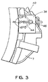
- the indicating means 38 includes a pointer 44 which is capable of turning about a fixed axis 46 with respect to a measuring means 48.
- the measuring means includes a series of numbers is shown which denotes an amount of piston travel. This amount of piston travel can range from approximately 0-4 inches. Note that although a particular indicating means is illustrated in the Figures, any well known type of indicating means along with a well known type of measuring means may be used to measure the amount of piston travel.
Landscapes
- Engineering & Computer Science (AREA)
- Mechanical Engineering (AREA)
- General Engineering & Computer Science (AREA)
- Transportation (AREA)
- Braking Arrangements (AREA)
- Valves And Accessory Devices For Braking Systems (AREA)
- Actuator (AREA)
Abstract
Description
- The present invention relates, in general, to a brake cylinder piston travel indicator and, more particularly, to a brake beam mounted brake cylinder piston travel indicator which is located in an easily viewable location for readily determining piston travel in truss-type railway vehicle brake assemblies.
- Freight trains typically undergo a pre-departure terminal test in which the air brake equipment of each car is inspected prior to the train being cleared to proceed from the train make-up yard. This inspection requires a trainman to "walk the train" visually checking each car's brake equipment. Prior art type truck mounted brake assemblies include a piston travel indicator attached to the brake cylinder assembly for monitoring piston travel to determine whether or not the brake equipment is functioning properly.
- The currently used piston travel indicator comprises an indicating means, such as a flag, which moves along a measuring means. This measuring means has an acceptable operating range or zone marked thereon. The inspector views the location of the flag with respect to the acceptable operating range to determine whether or not the braking equipment is functioning properly. For example, if the flag is below the range, then such would indicate that the slack adjuster trigger needs to be adjusted. If, on the other hand, the flag is above the range, such could indicate that either the slack adjuster is out of capacity and the brake shoes are too worn, or the slack adjuster is not functioning properly and requires maintenance.
- Due to the location of this piston travel indicator within the truck mounted brake assembly underneath the car, it is often difficult for the trainman to readily view the indicator and to make a proper determination as to the functioning of the braking equipment. It thus becomes burdensome to inspect the braking equipment of the train and consequently more time consuming to complete the terminal test.
- It is an object of the present invention to provide a brake cylinder piston travel indicator which is located in a readily viewable location for determining the amount of travel of a fluid activated piston.
- It is a further object of the invention to provide a brake cylinder piston travel indicator which may be readily viewed by train inspection personnel so that such personnel may make a proper determination regarding the functioning of the train's braking equipment.
- It is another object of the invention to position this brake cylinder piston travel indicator in a location on each braking assembly and/or on one or both sides of the railway vehicle so that train inspection personnel may quickly perform a pre-departure terminal test.
- It is yet another object of the invention to provide a brake cylinder piston travel indicator which may be mounted onto braking systems currently in use and is particularly applicable to truss-type brake assembly systems.
- In addition to the objects and advantages listed above, various other objects and advantages of the invention will become more readily apparent to persons skilled in the relevant art from a reading of the detailed description section of this document. The other objects and advantages will become particularly apparent when the detailed description is considered along with the drawings and claims presented herein.
- Briefly, and in accordance with the forgoing objects, the invention comprises a brake cylinder piston travel indicator for monitoring an amount of piston travel in a brake cylinder assembly in a railway braking system. The railway braking system includes a brake beam and a brake cylinder piston within the brake cylinder assembly which is in engagement with an end of a brake cylinder force transfer lever. The brake cylinder piston travel indicator of the invention comprises a rod member which is rotatably secured to and extends substantially parallel with at least a portion of the brake beam. A means is provided which associates the rod member with the cylinder force transfer lever and is capable of transferring a rotational force to the rod member. This rotational force is caused by activation of the piston in the brake cylinder assembly. At least one indicating means is provided which is engagable with a first end of the rod member and is capable of responding to the rotation of the rod member and indicating an amount of travel of the piston during activation thereof in the brake cylinder assembly.
-
- Figure 1 shows a plan view of a truss-type brake assembly currently in use upon which the cylinder piston travel indicator can be mounted.
- Figure 2 shows a partial view of a truss-type brake assembly including the cylinder piston travel indicator of the invention mounted thereon.
- Figure 3 shows an end view of the cylinder piston travel indicator of the invention.
-
- Before describing the invention in detail, the reader is advised that, for the sake of clarity and understanding, identical components having identical functions have been marked where possible with the same reference numerals in each of the Figures provided in this document.
- Referring now to Figures 1-3, there is shown a truss type braking system, generally designated as 100. The brake system comprises a pair of
brake beams compression member 4 and atension member 5. The brake beams are interconnected by a series of well known linkages. In the type of braking system illustrated in Figure 1, these linkages include a cylinderforce transfer lever 8, a slack adjuster 11, a non-cylinderforce transfer lever 9 and areturn push rod 16. Each of thebrake beams brake head 7 mounted at each end thereof. Apiston assembly 15 is also provided which is connected to thereturn push rod 16. Thebrake cylinder 15 has apiston 17 which is connected to afirst end 22 of the cylinderforce transfer lever 8. - As illustrated in Figure 2, the invention comprises a brake cylinder piston travel indicator, generally indicated as 24, for monitoring the amount of piston travel during a brake application and positioning an indicator depicting this movement in a readily viewable location on the railway vehicle.
- The brake cylinder piston travel indicator of the invention comprises a
rod member 25 which is rotatably secured to and extends substantially parallel with at least a portion of at least onebrake beam 2 of the braking system. - A means, generally designated as 28 is provided which associates the
rod member 25 with the cylinderforce transfer lever 8 and is capable of transferring a rotational force to therod member 25. This rotational force is caused by activation of thepiston 17 in thebrake cylinder assembly 15 during a braking application. - At least one indicating
means 38 is provided which is engagable with afirst end 26 of therod member 25 and is capable of responding to the rotation of therod member 25 and indicating an amount of travel of thepiston 17 during activation thereof in thebrake cylinder assembly 15. - An
aperture 40 is provided in at least one of thebrake heads 7 and thefirst end 26 ofrod member 25 extends through this aperture. The indicatingmeans 38 is mounted on thisfirst end 26 of therod member 25 such that it is positioned adjacent anouter surface 42 of thebrake head 7. Thus, this location of the indicatingmeans 38 allows train personnel to readily view the indicatingmeans 38. - Although not shown in Figure 2, one having ordinary skill in the art would recognize that the
rod member 25 of the cylinderpiston travel indicator 24 can extend substantially the entire length of the at least onebrake beam 2 in order to provide an indicatingmeans 38 on either side of the railway vehicle. If such is the case, then an aperture would be formed in thebrake head 7 positioned on the opposite side of thebrake beam 2 and a second end of therod member 25 would extend through this aperture. A second indicating means would be provided on the outer surface of thissecond brake head 7. - The
rod member 25 is rotatably secured to the brake beam by any well known means such as apillow block 50. More than onepillow block 50 may be used if necessary in order to sufficiently mount therod member 25 to thebrake beam 2. If the rod member extends the entire length of the brake beam, aU-shaped portion 52 may be provided so as to enable the rod to negotiate around thebrake cylinder 15 of the braking system. - The
means 28 for associating therod member 25 with the cylinderforce transfer lever 8 includes an extension means 30 affixed to and extending outward from asecond end 32 of the cylinderforce transfer lever 8. This extension means 30 is positioned adjacent the slack adjuster 11. A linkage means, generally designated as 33, is provided which extends toward thecompression member 4 of thebrake beam 2 at approximately 90 degrees with respect to the extension means 30. - The linkage means 33 includes a
jaw member 34 attached to the extension means 30. Aturning lever 36 is provided which is rigidly attached to the rod member at one end. The opposite end of the turninglever 36 is pivotally attached to a pivotal attachment means 35. The pivotal attachment means 35 pivotally connects thejaw member 34 to the turninglever 36. The turninglever 36 extends in a substantially vertical direction with respect to therod member 25 and the pivotal attachment means 35 such that movement of thisturning lever 36 causes the rod member to rotate in a predetermined direction. - As illustrated in Figure 3, at least one of the
ends 26 of therod member 25 is attached to an indicatingmeans 38 which is located in a viewable location on the railway vehicle. The indicatingmeans 38 includes apointer 44 which is capable of turning about afixed axis 46 with respect to ameasuring means 48. In the illustrated embodiment, the measuring means includes a series of numbers is shown which denotes an amount of piston travel. This amount of piston travel can range from approximately 0-4 inches. Note that although a particular indicating means is illustrated in the Figures, any well known type of indicating means along with a well known type of measuring means may be used to measure the amount of piston travel. - The invention has been described in such full, clear, concise and exact terms so as to enable any person skilled in the art to which it pertains to make and use the same. It should be understood that variations, modifications, equivalents and substitutions for components of the specifically described embodiments of the invention may be made by those skilled in the art without departing from the spirit and scope of the invention as set forth in the appended claims. Persons who possess such skill will also recognize that the foregoing description is merely illustrative and not intended to limit any of the ensuing claims to any particular narrow interpretation.
Claims (20)
- A brake cylinder piston travel indicator for monitoring an amount of piston travel in a brake cylinder assembly in a railway braking system, such railway braking system including a brake beam and a brake cylinder piston in engagement with a first end of a brake cylinder force transfer lever, said piston travel indicator comprising:(a) a rod member rotatably secured to and extending substantially parallel with at least a portion of such brake beam;(b) means for associating said rod member with such cylinder force transfer lever, said means capable of transferring a rotational force to said rod member, said rotational force being initiated by activation of such piston in such brake cylinder assembly; and(c) at least one indicating means engagable with a first end of said rod member, said indicating means capable of responding to said rotation of said rod member and indicating an amount of travel of such piston during activation thereof in such brake cylinder assembly.
- A brake cylinder piston travel indicator as recited in claim 1 wherein said rod member extends parallel with and substantially along the length of such brake beam.
- A brake cylinder piston travel indicator as recited in claim 1 wherein such brake beam includes a pair of brake heads at opposite ends thereof, at least one of said brake heads including an aperture and said first end of said rod member is capable of extending through such aperture.
- A brake cylinder piston travel indicator as recited in claim 3 wherein said indicating means is engagable with said first end of said rod member such that said indicating means is positioned adjacent an outer surface of such at least one brake head.
- A brake cylinder piston travel indicator as recited in claim 3 wherein each of such brake heads includes an aperture and a first end of said rod member extends through an aperture in a first brake head and a second end of said rod member extends through an aperture in a second brake head.
- A brake cylinder piston travel indicator as recited in claim 5 wherein a first and second indicating means are provided, said first indicating means being engagable with said first end of said rod member and said second indicating means being engagable with said second end of said rod member.
- A brake cylinder piston travel indicator as recited in claim 6 wherein said first and second indicating means are engagable with said first and second ends of said rod member such that said indicating means are capable of being positioned adjacent outer surfaces of such first and second brake heads.
- A brake cylinder piston travel indicator as recited in claim 1 wherein said indicating means includes a pointer capable of turning about a fixed axis with respect to a measuring means.
- A brake cylinder piston travel indicator as recited in claim 8 wherein said measuring means includes a series of numbers which denote an amount of piston travel.
- A brake cylinder piston travel indicator as recited in claim 9 wherein said amount of piston travel measured includes a range of approximately 0-4 inches.
- A brake cylinder piston travel indicator as recited in claim 1 wherein said means for associating said rod member with such cylinder force transfer lever includes an extension means affixed to and extending outward from a second end of such cylinder force transfer lever.
- A brake cylinder piston travel indicator as recited in claim 11 wherein such braking system includes a slack adjuster connected to said second end of such cylinder force transfer lever and said extension means is adjacent such slack adjuster.
- A brake cylinder piston travel indicator as recited in claim 11 wherein said means for associating said rod member with such cylinder force transfer lever further includes a linkage means extending toward such brake beam at approximately 90 degrees with respect to said extension means.
- A brake cylinder piston travel indicator as recited in claim 13 wherein said linkage means includes a jaw member attached to said extension means, a turning lever attached to said rod member and a pivotal attachment means pivotally connecting said jaw member to said turning lever.
- A brake cylinder piston travel indicator as recited in claim 14 wherein said turning lever extends in a substantially vertical direction with respect to said rod member and said pivotal attachment means such that movement of said turning member causes said rod member to rotate in a predetermined direction.
- A brake cylinder piston travel indicator as recited in claim 1 wherein said rod member is rotatably secured to such brake beam by means of at least one pillow block.
- A brake cylinder piston travel indicator as recited in claim 1 wherein said rod member includes a U-shaped portion positioned around such brake cylinder assembly.
- In combination with a truss type braking system having a pair of brake beams interconnected by a series of linkages, each of said brake beams having a brake head mounted at each end thereof, a brake cylinder having a piston, and a brake cylinder force transfer lever having an end in engagement with said brake cylinder piston and wherein the improvement comprises a brake cylinder piston travel indicator comprising;(a) a rod member rotatably secured to and extending substantially parallel with at least a portion of at least one of said brake beams;(b) means for associating said rod member with said cylinder force transfer lever, said means capable of transferring a rotational force to said rod member, said rotational force being initiated by activation of said piston in said brake cylinder assembly; and(c) at least one indicating means engagable with a first end of said rod member, said indicating means capable of responding to said rotation of said rod member and indicating an amount of travel of said piston during activation thereof in said brake cylinder assembly.
- A combination as recited in claim 18 wherein said brake cylinder piston travel indicator includes an indicating means mounted on each side of said at least one brake beam.
- A combination as recited in claim 18 wherein said means for associating said rod member with said cylinder force transfer lever includes an extension means attached to an end of said force transfer lever at a location remote from said brake cylinder and a linkage means extending toward such brake beam at approximately 90 degrees with respect to said extension means, said linkage means including a jaw member attached to said extension means, a turning lever attached to said rod member and a pivotal attachment means pivotally connecting said jaw member to said turning lever, said turning lever extending in a substantially vertical direction with respect to said rod member and said pivotal attachment means such that movement of said turning member causes said rod member to rotate in a predetermined direction.
Applications Claiming Priority (2)
| Application Number | Priority Date | Filing Date | Title |
|---|---|---|---|
| US09/687,340 US6364068B1 (en) | 2000-10-13 | 2000-10-13 | Brake cylinder piston travel indicator |
| US687340 | 2000-10-13 |
Publications (1)
| Publication Number | Publication Date |
|---|---|
| EP1197414A1 true EP1197414A1 (en) | 2002-04-17 |
Family
ID=24760066
Family Applications (1)
| Application Number | Title | Priority Date | Filing Date |
|---|---|---|---|
| EP01202075A Withdrawn EP1197414A1 (en) | 2000-10-13 | 2001-05-31 | Brake cylinder piston travel indicator |
Country Status (9)
| Country | Link |
|---|---|
| US (1) | US6364068B1 (en) |
| EP (1) | EP1197414A1 (en) |
| JP (1) | JP2002173027A (en) |
| CN (1) | CN1348890A (en) |
| AU (1) | AU780034B2 (en) |
| BR (1) | BR0102929A (en) |
| CA (1) | CA2346615C (en) |
| MX (1) | MXPA01010316A (en) |
| ZA (1) | ZA200103721B (en) |
Families Citing this family (5)
| Publication number | Priority date | Publication date | Assignee | Title |
|---|---|---|---|---|
| US8049608B2 (en) * | 2009-06-02 | 2011-11-01 | Wabtec Holding Corp. | System and method for calculating electrically controlled pneumatic (ECP) brake cylinder piston travel |
| RU2609846C2 (en) * | 2011-12-27 | 2017-02-06 | УОБТЕК ЭмЗетТи | Built-in car bogie brake and brake shoe wear compensator for use with built-in car bogie brake |
| CN102785676B (en) * | 2012-08-21 | 2015-07-15 | 齐齐哈尔轨道交通装备有限责任公司 | Indication device of vehicle brake release state as well as brake system and vehicle |
| AU2014278372B2 (en) * | 2013-06-10 | 2017-08-03 | Wabtec Holding Corp. | Corrective device for uneven brake shoe wear |
| KR102276206B1 (en) * | 2019-12-24 | 2021-07-13 | 한국철도기술연구원 | Status indicator for gauge-changeable wheelset |
Citations (6)
| Publication number | Priority date | Publication date | Assignee | Title |
|---|---|---|---|---|
| DE1258445B (en) * | 1965-10-28 | 1968-01-11 | Kloeckner Humboldt Deutz Ag | Device for monitoring the braking position and the state of wear of the brake shoes on disc brake systems of rail vehicles that interact with automatic brake linkage adjusters |
| DE2525469B1 (en) * | 1975-06-07 | 1976-03-11 | Knorr Bremse Gmbh | Pressurized medium-operated display device for pressurized vehicle brakes |
| US5492203A (en) * | 1995-03-10 | 1996-02-20 | Westinghouse Air Brake Company | Railroad car brake cylinder piston travel indicator and mount therefor |
| US5885664A (en) * | 1997-04-07 | 1999-03-23 | E.J.P. Machine, Inc. | Process for providing a piston travel indicator for a railroad car brake assembly |
| US5913385A (en) * | 1997-02-20 | 1999-06-22 | Spectra Products Inc. | Visual brake stroke indicator |
| US6082502A (en) * | 1998-08-18 | 2000-07-04 | Westinghouse Air Brake Company | Cable operated piston travel indicator |
Family Cites Families (2)
| Publication number | Priority date | Publication date | Assignee | Title |
|---|---|---|---|---|
| US3511543A (en) * | 1967-11-14 | 1970-05-12 | Abex Corp | Hydraulic cylinder controls for producing confluent pressure streams |
| US5441128A (en) * | 1994-07-22 | 1995-08-15 | Hoyt; Gordon C. | Reference bracket means for brake stroke length adjustment gauge |
-
2000
- 2000-10-13 US US09/687,340 patent/US6364068B1/en not_active Expired - Fee Related
-
2001
- 2001-05-07 CA CA002346615A patent/CA2346615C/en not_active Expired - Fee Related
- 2001-05-08 ZA ZA200103721A patent/ZA200103721B/en unknown
- 2001-05-09 AU AU43787/01A patent/AU780034B2/en not_active Ceased
- 2001-05-31 EP EP01202075A patent/EP1197414A1/en not_active Withdrawn
- 2001-06-19 CN CN01121990A patent/CN1348890A/en active Pending
- 2001-07-17 BR BR0102929-0A patent/BR0102929A/en not_active IP Right Cessation
- 2001-10-05 JP JP2001310203A patent/JP2002173027A/en not_active Withdrawn
- 2001-10-12 MX MXPA01010316A patent/MXPA01010316A/en unknown
Patent Citations (6)
| Publication number | Priority date | Publication date | Assignee | Title |
|---|---|---|---|---|
| DE1258445B (en) * | 1965-10-28 | 1968-01-11 | Kloeckner Humboldt Deutz Ag | Device for monitoring the braking position and the state of wear of the brake shoes on disc brake systems of rail vehicles that interact with automatic brake linkage adjusters |
| DE2525469B1 (en) * | 1975-06-07 | 1976-03-11 | Knorr Bremse Gmbh | Pressurized medium-operated display device for pressurized vehicle brakes |
| US5492203A (en) * | 1995-03-10 | 1996-02-20 | Westinghouse Air Brake Company | Railroad car brake cylinder piston travel indicator and mount therefor |
| US5913385A (en) * | 1997-02-20 | 1999-06-22 | Spectra Products Inc. | Visual brake stroke indicator |
| US5885664A (en) * | 1997-04-07 | 1999-03-23 | E.J.P. Machine, Inc. | Process for providing a piston travel indicator for a railroad car brake assembly |
| US6082502A (en) * | 1998-08-18 | 2000-07-04 | Westinghouse Air Brake Company | Cable operated piston travel indicator |
Also Published As
| Publication number | Publication date |
|---|---|
| MXPA01010316A (en) | 2002-06-04 |
| ZA200103721B (en) | 2001-11-08 |
| BR0102929A (en) | 2002-06-04 |
| US6364068B1 (en) | 2002-04-02 |
| CA2346615C (en) | 2005-02-15 |
| AU4378701A (en) | 2002-04-18 |
| AU780034B2 (en) | 2005-02-24 |
| JP2002173027A (en) | 2002-06-18 |
| CA2346615A1 (en) | 2002-04-16 |
| CN1348890A (en) | 2002-05-15 |
Similar Documents
| Publication | Publication Date | Title |
|---|---|---|
| US5699880A (en) | Brake adjustment indicator | |
| US12269451B2 (en) | Systems and methods for monitoring brake systems on railway assets | |
| CA2960276C (en) | Brake force sensor arrangement for a brake unit | |
| US20090040503A1 (en) | System and method for analyzing rolling stock wheels | |
| US6135242A (en) | Braking system for a vehicle having a stroke indicator | |
| US6364068B1 (en) | Brake cylinder piston travel indicator | |
| US4296707A (en) | Railroad car hand brake signal device | |
| US8049608B2 (en) | System and method for calculating electrically controlled pneumatic (ECP) brake cylinder piston travel | |
| CA2464497C (en) | Apparatus for measuring piston travel | |
| US6082502A (en) | Cable operated piston travel indicator | |
| CA2149963C (en) | Railroad car brake cylinder piston travel indicator and mount therefor | |
| US6662641B2 (en) | Method and device to measure the brake force for railroad vehicles | |
| RU2746868C2 (en) | Method and the system for controlling the hand brake of a railway car | |
| CA2546121A1 (en) | System, method, and apparatus for training railroad personnel in rail vehicle safety and maintenance | |
| US6213254B1 (en) | Air-brake rod travel indicator | |
| MXPA99007632A (en) | Travel indicator of the piston operated by ca | |
| CA2245285C (en) | Improved braking system for a vehicle | |
| Spaulding et al. | Design, Fabrication and Evaluation of Prototype Wayside Brake Inspection Sensors | |
| CA2414919A1 (en) | Piston travel indicator for rail car | |
| JP2003072546A (en) | Hand brake tightened and loosened state display device for rolling stock |
Legal Events
| Date | Code | Title | Description |
|---|---|---|---|
| PUAI | Public reference made under article 153(3) epc to a published international application that has entered the european phase |
Free format text: ORIGINAL CODE: 0009012 |
|
| AK | Designated contracting states |
Kind code of ref document: A1 Designated state(s): AT BE CH CY DE DK ES FI FR GB GR IE IT LI LU MC NL PT SE TR Kind code of ref document: A1 Designated state(s): DE FR GB IT |
|
| AX | Request for extension of the european patent |
Free format text: AL;LT;LV;MK;RO;SI |
|
| 17P | Request for examination filed |
Effective date: 20021017 |
|
| AKX | Designation fees paid |
Free format text: DE FR GB IT |
|
| STAA | Information on the status of an ep patent application or granted ep patent |
Free format text: STATUS: THE APPLICATION HAS BEEN WITHDRAWN |
|
| 18W | Application withdrawn |
Effective date: 20050319 |