EP1197408A2 - Fahrdynamik-Regelverfahren eines Kraftfahrzeuges - Google Patents
Fahrdynamik-Regelverfahren eines Kraftfahrzeuges Download PDFInfo
- Publication number
- EP1197408A2 EP1197408A2 EP01122835A EP01122835A EP1197408A2 EP 1197408 A2 EP1197408 A2 EP 1197408A2 EP 01122835 A EP01122835 A EP 01122835A EP 01122835 A EP01122835 A EP 01122835A EP 1197408 A2 EP1197408 A2 EP 1197408A2
- Authority
- EP
- European Patent Office
- Prior art keywords
- adhesion
- determined
- vehicle
- wheel
- control method
- Prior art date
- Legal status (The legal status is an assumption and is not a legal conclusion. Google has not performed a legal analysis and makes no representation as to the accuracy of the status listed.)
- Withdrawn
Links
- 238000000034 method Methods 0.000 title claims abstract description 16
- 230000002349 favourable effect Effects 0.000 claims description 3
- 238000012913 prioritisation Methods 0.000 claims description 2
- 230000001133 acceleration Effects 0.000 description 14
- 238000004364 calculation method Methods 0.000 description 7
- 230000000694 effects Effects 0.000 description 4
- 239000000725 suspension Substances 0.000 description 4
- 230000008859 change Effects 0.000 description 3
- 230000004069 differentiation Effects 0.000 description 3
- 239000003381 stabilizer Substances 0.000 description 3
- 230000008901 benefit Effects 0.000 description 2
- 238000011161 development Methods 0.000 description 2
- 230000018109 developmental process Effects 0.000 description 2
- 230000006872 improvement Effects 0.000 description 2
- 239000006096 absorbing agent Substances 0.000 description 1
- 230000009471 action Effects 0.000 description 1
- 230000006835 compression Effects 0.000 description 1
- 238000007906 compression Methods 0.000 description 1
- 238000004590 computer program Methods 0.000 description 1
- 238000010276 construction Methods 0.000 description 1
- 238000013016 damping Methods 0.000 description 1
- 230000003247 decreasing effect Effects 0.000 description 1
- 230000001419 dependent effect Effects 0.000 description 1
- 238000010586 diagram Methods 0.000 description 1
- 238000005516 engineering process Methods 0.000 description 1
- 230000005484 gravity Effects 0.000 description 1
- 230000035939 shock Effects 0.000 description 1
- 230000006641 stabilisation Effects 0.000 description 1
- 238000011105 stabilization Methods 0.000 description 1
- 230000002123 temporal effect Effects 0.000 description 1
- 230000007704 transition Effects 0.000 description 1
Images


Classifications
-
- B—PERFORMING OPERATIONS; TRANSPORTING
- B60—VEHICLES IN GENERAL
- B60T—VEHICLE BRAKE CONTROL SYSTEMS OR PARTS THEREOF; BRAKE CONTROL SYSTEMS OR PARTS THEREOF, IN GENERAL; ARRANGEMENT OF BRAKING ELEMENTS ON VEHICLES IN GENERAL; PORTABLE DEVICES FOR PREVENTING UNWANTED MOVEMENT OF VEHICLES; VEHICLE MODIFICATIONS TO FACILITATE COOLING OF BRAKES
- B60T8/00—Arrangements for adjusting wheel-braking force to meet varying vehicular or ground-surface conditions, e.g. limiting or varying distribution of braking force
- B60T8/17—Using electrical or electronic regulation means to control braking
- B60T8/1755—Brake regulation specially adapted to control the stability of the vehicle, e.g. taking into account yaw rate or transverse acceleration in a curve
-
- B—PERFORMING OPERATIONS; TRANSPORTING
- B60—VEHICLES IN GENERAL
- B60T—VEHICLE BRAKE CONTROL SYSTEMS OR PARTS THEREOF; BRAKE CONTROL SYSTEMS OR PARTS THEREOF, IN GENERAL; ARRANGEMENT OF BRAKING ELEMENTS ON VEHICLES IN GENERAL; PORTABLE DEVICES FOR PREVENTING UNWANTED MOVEMENT OF VEHICLES; VEHICLE MODIFICATIONS TO FACILITATE COOLING OF BRAKES
- B60T2210/00—Detection or estimation of road or environment conditions; Detection or estimation of road shapes
- B60T2210/10—Detection or estimation of road conditions
- B60T2210/12—Friction
-
- B—PERFORMING OPERATIONS; TRANSPORTING
- B60—VEHICLES IN GENERAL
- B60T—VEHICLE BRAKE CONTROL SYSTEMS OR PARTS THEREOF; BRAKE CONTROL SYSTEMS OR PARTS THEREOF, IN GENERAL; ARRANGEMENT OF BRAKING ELEMENTS ON VEHICLES IN GENERAL; PORTABLE DEVICES FOR PREVENTING UNWANTED MOVEMENT OF VEHICLES; VEHICLE MODIFICATIONS TO FACILITATE COOLING OF BRAKES
- B60T2240/00—Monitoring, detecting wheel/tyre behaviour; counteracting thereof
- B60T2240/06—Wheel load; Wheel lift
-
- B—PERFORMING OPERATIONS; TRANSPORTING
- B60—VEHICLES IN GENERAL
- B60T—VEHICLE BRAKE CONTROL SYSTEMS OR PARTS THEREOF; BRAKE CONTROL SYSTEMS OR PARTS THEREOF, IN GENERAL; ARRANGEMENT OF BRAKING ELEMENTS ON VEHICLES IN GENERAL; PORTABLE DEVICES FOR PREVENTING UNWANTED MOVEMENT OF VEHICLES; VEHICLE MODIFICATIONS TO FACILITATE COOLING OF BRAKES
- B60T2270/00—Further aspects of brake control systems not otherwise provided for
- B60T2270/86—Optimizing braking by using ESP vehicle or tyre model
Definitions
- the invention relates to a driving dynamics control method for a particular four-wheel motor vehicle, which between the wheels and the road to The available adhesion potential is determined and compared with the currently determined utilization of the adhesion, a adhesion reserve is determined.
- a driving dynamics control method for a particular four-wheel motor vehicle which between the wheels and the road to The available adhesion potential is determined and compared with the currently determined utilization of the adhesion, a adhesion reserve is determined.
- DE 198 22 481 A1 referred to DE 42 00 997 A1.
- driving dynamics control subsumed and take into account generally the transverse dynamic and longitudinal dynamic state of a Vehicle. This condition should then be activated through active interventions e.g. in the Steering system and / or brake system and / or drive system of the motor vehicle be influenced appropriately. So describes, for example DE 198 22 481 A1 a driving stability control device for a vehicle, that a front right, a front left, a back right and a rear left wheel and a braking system for optional separate Braking of each of the wheels.
- the control device estimates then a ratio of a longitudinal force to a vertical load applied to each of the Wheels acts, off, and actuates the when braking is desired Vehicle braking system in such a way that the stated ratio is one on each wheel takes essentially the same value.
- the respective vertical load from a vehicle weight assumed to be constant is estimated in the knowledge of the vehicle focus.
- the solution to this problem is characterized in that in addition to the forces acting in the horizontal plane, the vertical movements of the motor vehicle body relative to the wheels are also taken into account when determining the adhesion reserve.
- body level sensors are preferably provided in the area of the vehicle wheels, with which these vertical movements can be determined and analyzed and from whose signals the wheel load oriented in the vertical direction is then determined for each wheel.
- the respective adhesion potential is determined by a calculation method, which the signals various chassis sensors as well as chassis-specific characteristics of the Vehicle processed.
- this calculation also takes into account that the so-called construction of the vehicle, i.e. essentially the Vehicle body, moved vertically in relation to the wheels, from which Changes in the wheel load result in the vertical direction between the wheel and roadway, and that in the horizontal plane between the wheel and Roadway transmissible traction potential also determined.
- a driving dynamics control method is described in the Sense of a preferred embodiment for a four-wheel motor vehicle, in particular a passenger car, explained with the one of the well-known driving dynamics control systems and any two-axis level control Is provided.
- it allows one such two-axis level control compared to the level of the body to change the road individually for each wheel, i.e. for everyone - preferred as Independent suspension trained - suspension can be the distance between the floor panel of the vehicle body and the wheel in certain areas can be set arbitrarily.
- the driver's request can be sensed with the three last-mentioned sensors be, namely a steering movement for a desired cornering as well Braking and "accelerating" for a desired negative or positive acceleration in the longitudinal direction of the vehicle.
- the driving behavior of the vehicle as a result of the driver specification be determined.
- the driving dynamics control system can then start the so-called target driving state determine in a known manner whether the vehicle is still stable Course is or whether the actuators of the control system, for example, by interventions in the braking system or in the control of the vehicle drive unit must take corrective action.
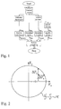
- the invention it is now possible, for example or preferably, to determine the current wheel load from the deflection state of each wheel using the level sensors on the individual wheels according to the attached diagram according to FIG .
- the naturally known characteristics of the body spring elements, via which the body is supported in the vertical direction on the wheels, as well as the assigned stabilizer rates and, if necessary, the characteristics of the shock absorbers, which are also provided as usual, must be taken into account.
- the wheel strokes of the individual wheels are known, first of all the part of the wheel load contained therein is calculated due to the equilateral deflection. Taking into account the wheel stroke difference The share of the wheels of an axle of the vehicle is due mutual compression determined. To take the dynamic forces into account can also form the wheel lifting speed through time differentiation of the level sensor signal, which then together with the damper characteristic and associated translation the damper force results. By further differentiation can by Determine the wheel stroke acceleration also the inertia of the so-called unsprung mass.
- the wheel load of everyone Rades can be determined as desired by adding all four parts, so as shown in Fig.1, according to the usual technical terminology a force with the letter “F” and the vertical direction with the coordinate "z” is designated, while the letter “h” denotes a height or Symbolizes longitudinal extension in the z direction and the temporal differentiation indicated by a point above the size to be differentiated (here: h) is.
- the maximum possible tire forces are now in the Horizontal plane, i.e. in the longitudinal direction of the vehicle (identified by the coordinate "x") and in the vehicle transverse direction (identified by the coordinate "y") to be determined.
- a coefficient of friction sensor for determining the Coefficient of friction between wheel or tire and road a significant improvement expect the accuracy, but not on such a coefficient of friction can be used, one can in principle already known friction value estimation of an already known driving dynamics control system be used.
- Such an estimation of friction is For example, also in the electronics that have become increasingly popular in recent times Stabilization programs (ESP or DSC called) included.
- each individual ellipse surface for the associated wheel load indicates the maximum available adhesion potential, which - as shown in Fig.3a - results from the vectorial addition of the two horizontal components F x, max and F y, max .
- the adhesion limit of the individual tire (s) (or wheel) is now determined. For practical use, however, it is not this adhesion limit itself that is of interest, but the distance between the current operating point of the tire forces and this adhesion limit. So it is interested in the adhesion reserve that is still available at the current operating point, ie the adhesion potential still remaining, taking into account the current utilization of the adhesion.
- This adhesion reserve is formed (in the figurative representation of the so-called adhesion cone) by the shortest distance between the maximum available adhesion potential and the current adhesion utilization, i.e. between the outer surface of the adhesion cone and the current one operating point.
- This so-called adhesion reserve is now determined in a third calculation step, which is shown in principle in FIG .
- the instantaneous tire forces are required for this, some of which are already known, namely in the form of the already determined wheel load F z , or which can be estimated (in the horizontal plane) in a known manner using the sensors mentioned.
- the oriented lateral force y in the transverse direction F y may be approximately determined from the lateral and yaw acceleration and in Fzg. longitudinal direction x-oriented longitudinal force F x from the longitudinal acceleration or from the current output torque of the Fzg. drive apparatus, as well as from the Brake pressures can be determined.
- the vector ⁇ F z, max leads from the lower plane of the ellipse to an ellipse above it, in which an operating point with these horizontal forces F x0 and F y0 lies exactly on the edge of the ellipse and thus fully utilizes the available adhesion potential.
- adhesion controller is a designates, for example, the scope of functions contained within a driving dynamics controller, which serves to optimize the adhesion. Preferably done now a prioritization or division of the calculated in this adhesion controller or transmitted adhesion potential to the control functions involved according to a fixed key.
- a driving dynamics controller which serves to optimize the adhesion.
- a prioritization or division of the calculated in this adhesion controller or transmitted adhesion potential to the control functions involved according to a fixed key Preferably done now a prioritization or division of the calculated in this adhesion controller or transmitted adhesion potential to the control functions involved according to a fixed key.
- transverse dynamic Systems can also be a driving dynamics controller according to the invention combined with one or more vertical dynamic control systems such as with an electronic damping force adjustment, a stabilizer adjustment or an active suspension that is primarily of improvement serve the driving comfort. Because these systems are the wheel loads can be influenced directly, they can also improve driving behavior and driving safety.
- the so-called the determination of the current adhesion offer beyond the Task compare and prioritize their implementation.
- driving safety should or should be preferred stand, according to which generally good driving behavior is important can and what is the last (with the least importance) so-called comfort functions can connect.
- braking operations initiated by the driver Priority over all other control functions; i.e. all control signals to the possible actuators, influenced the driving dynamics can be, with regard to their effects on the adhesion checked and, if necessary, corrected such that a maximum braking deceleration is achieved.
- the vehicle during a Stability control in the curve braked by the driver so they can Braking forces are distributed in such a way that in addition to the shortest possible Braking distance also sets a largely stable cornering behavior.
Landscapes
- Engineering & Computer Science (AREA)
- Transportation (AREA)
- Mechanical Engineering (AREA)
- Vehicle Body Suspensions (AREA)
- Regulating Braking Force (AREA)
- Electric Propulsion And Braking For Vehicles (AREA)
- Arrangement And Driving Of Transmission Devices (AREA)
Abstract
Description
Die Lösung dieser Aufgabe ist dadurch gekennzeichnet, daß neben den in der Horizontalebene wirkenden Kräften zusätzlich die Vertikalbewegungen des Kraftfahrzeug-Aufbaus gegenüber den Rädern bei der Bestimmung der Kraftschluss-Reserve berücksichtigt werden. Bevorzugt sind hierfür im Bereich der Fahrzeug-Räder Aufbau-Höhenstandssensoren vorgesehen, mit denen diese Vertikalbewegungen festgestellt und analysiert werden können und aus deren Signalen dann für jedes Rad die in Vertikalrichtung orientierte Radlast bestimmt wird. Vorteilhafte Weiterbildungen sind Inhalt der weiteren Unteransprüche.
- 4 Höhenstandssensoren zur Messung der Ein- und Ausfederwege des Aufbaus an den einzelnen Radaufhängungen
- 4 Raddrehzahlfühler, d.h. die sog. ABS-Sensoren
- ein Drehraten- oder Giergeschwindigkeitssensor
- ein Querbeschleunigungssensor,
- ein Lenkwinkelsensor
- zumindest ein Bremsdrucksensor, sowie
- ein Drosselklappenwinkelsensor oder ein adäquates Signal aus der Steuerungselektronik des Fzg.-Antriebsaggregates zur Ermittlung von dessen Drehmoment- oder Leistungsabgabe.
Ausgehend von einem aktuellen Betriebspunkt auf der unteren Ellipse, der durch die Vertikalkraftkomponente Fz0 sowie die Längskraft Fx0 und die Seitenkraft Fy0 beschrieben ist - (diese Komponenten stellen die momentane Kraftschluss-Ausnutzung dar) -, werden einerseits die jeweiligen Kraftschlußreserven in x- und y-Richtung (nämlich ΔFx,max und ΔFy,max) bestimmt. Gleichzeitig wird angegeben, wie stark sich die Vertikalkraft noch ändern dürfte, bis das Rad an seiner Kraftschluss-Grenze angelangt ist. Bspw. gibt in Fig.5 der Vektor ΔFz,max an, wie weit das Rad noch ausfedern dürfte, bis bei unveränderten Horizontalkräften das zur Verfügung stehende Kraftschluss-Potential ausgeschöpft ist. Wie ersichtlich führt der Vektor ΔFz,max von der unteren Ellipsen-Ebene zu einer darüber liegenden Ellipse, in welcher ein Betriebspunkt mit diesen Horizontal-Kräften Fx0 und Fy0 exakt auf dem Ellipsenrand liegt und somit das zur Verfügung stehende Kraftschlußpotential vollständig ausschöpft.
Claims (5)
- Fahrdynamik-Regelverfahren für ein insbesondere vierrädriges Kraftfahrzeug, wobei das zwischen Rädern und Fahrbahn zur Verfügung stehende Kraftschluss-Potential ermittelt und durch Vergleich mit der ebenfalls ermittelten momentanen Kraftschluss-Ausnutzung eine Kraftschluss-Reserve bestimmt wird,
dadurch gekennzeichnet, daß neben den in der Horizontalebene wirkenden Kräften zusätzlich die Vertikalbewegungen des Kraftfahrzeug-Aufbaus gegenüber den Rädern bei der Bestimmung der Kraftschluss-Reserve berücksichtigt werden. - Fahrdynamik-Regelverfahren nach Anspruch 1,
dadurch gekennzeichnet, daß durch Multiplikation der in Vertikalrichtung orientierten Radlast mit einem geschätzten oder mittels eines Sensors ermittelten Reibwert zwischen Radreifen und Fahrbahn die vom Radreifen maximal übertragbare Horizontalkraft ermittelt wird, woraus mit den geeignet geschätzten aktuellen Werten für die in der Horizontalebene wirkende Längskraft und Seitenkraft die Kraftschluss-Reserven in Fahrzeug-Längsrichtung und in Fahrzeug-Querrichtung und in Vertikalrichtung ermittelt werden. - Fahrdynamik-Regelverfahren nach Anspruch 2,
dadurch gekennzeichnet, daß die ermittelten Kraftschluss-Reserven einem sog. Kraftschlussregler übermittelt werden, der unter Berücksichtigung des gewünschten Fahrmanövers eine günstige Nutzung des aktuellen Kraftschlußangebotes veranlaßt. - Fahrdynamik-Regelverfahren nach Anspruch 3,
dadurch gekennzeichnet, dass im Kraftschluss-Regler eine Priorisierung vorgenommen wird, dahingehend, dass Bremsvorgänge im Hinblick auf die Fahrsicherheit die höchste Priorität erhalten, während einem guten Fahrverhalten sowie allgemeinen Komfortfunktionen eine geringere Priorität zugeordnet wird. - Fahrdynamik-Regelverfahren nach einem der vorangegangenen Ansprüche,
dadurch gekennzeichnet, dass die in Vertikalrichtung orientierte Radlast aus den Signalen von an jedem Rad vorgesehenen Aufbau-Höhenstandssensoren bestimmt wird.
Applications Claiming Priority (2)
| Application Number | Priority Date | Filing Date | Title |
|---|---|---|---|
| DE2000150421 DE10050421A1 (de) | 2000-10-12 | 2000-10-12 | Fahrdynamik-Regelverfahren eines Kraftfahrzeuges |
| DE10050421 | 2000-10-12 |
Publications (2)
| Publication Number | Publication Date |
|---|---|
| EP1197408A2 true EP1197408A2 (de) | 2002-04-17 |
| EP1197408A3 EP1197408A3 (de) | 2003-02-05 |
Family
ID=7659454
Family Applications (1)
| Application Number | Title | Priority Date | Filing Date |
|---|---|---|---|
| EP01122835A Withdrawn EP1197408A3 (de) | 2000-10-12 | 2001-09-22 | Fahrdynamik-Regelverfahren eines Kraftfahrzeuges |
Country Status (2)
| Country | Link |
|---|---|
| EP (1) | EP1197408A3 (de) |
| DE (1) | DE10050421A1 (de) |
Cited By (3)
| Publication number | Priority date | Publication date | Assignee | Title |
|---|---|---|---|---|
| DE102006008214A1 (de) * | 2006-02-22 | 2007-08-30 | Audi Ag | Radschlupfregelsystem und Verfahren zum Regeln von Bewegungen von Rädern eines Fahrzeugs |
| WO2007138223A1 (fr) * | 2006-05-31 | 2007-12-06 | Renault S.A.S. | Dispositif et procede de controle des efforts sur un vehicule a quatre roues motrices |
| WO2018108533A1 (de) * | 2016-12-16 | 2018-06-21 | Volkswagen Aktiengesellschaft | Verfahren zum schätzen eines reibwerts einer fahrbahn mittels eines kraftfahrzeugs sowie steuervorrichtung und kraftfahrzeug |
Families Citing this family (7)
| Publication number | Priority date | Publication date | Assignee | Title |
|---|---|---|---|---|
| DE10158026B4 (de) | 2001-11-27 | 2005-11-24 | Lucas Automotive Gmbh | Verfahren zum Betreiben eines Antiblockiersystems |
| DE102004032730B4 (de) | 2004-07-07 | 2020-06-25 | Bayerische Motoren Werke Aktiengesellschaft | Verfahren zum Bestimmen der Reifenlängssteifigkeit |
| JP5752724B2 (ja) | 2013-02-08 | 2015-07-22 | 本田技研工業株式会社 | 車両用旋回制御装置 |
| DE102014006191A1 (de) | 2014-04-30 | 2015-11-05 | Audi Ag | Verfahren zum Betreiben einer Fahrerassistenzeinrichtung für ein Kraftfahrzeug sowie entsprechende Fahrerassistenzeinrichtung |
| GB2531327B (en) * | 2014-10-17 | 2017-08-23 | Jaguar Land Rover Ltd | Traction control system modified by vehicle pitch and/or heave |
| US10696294B2 (en) | 2017-10-03 | 2020-06-30 | GM Global Technology Operations LLC | Actively controlling rear differential coupling with aero load information |
| DE102020118706B4 (de) | 2020-07-15 | 2024-03-28 | Mercedes-Benz Group AG | Verfahren zur Prüfung der Eignung einer Solltrajektorie für eine Trajektorienregelung eines Fahrzeugs |
Citations (2)
| Publication number | Priority date | Publication date | Assignee | Title |
|---|---|---|---|---|
| DE4200997A1 (de) | 1992-01-16 | 1993-07-22 | Steyr Daimler Puch Ag | Verfahren zur ermittlung der fahrdynamischen sicherheitsreserve von kraftfahrzeugen |
| DE19822481A1 (de) | 1997-05-20 | 1998-11-26 | Toyota Motor Co Ltd | Fahrstabilitätssteuerungsvorrichtung eines Fahrzeugs durch Vereinheitlichen des Verhältnisses der Längs-/Seitenkraft zu einer Vertikallast eines jeden Rades |
Family Cites Families (4)
| Publication number | Priority date | Publication date | Assignee | Title |
|---|---|---|---|---|
| DE4218034B4 (de) * | 1992-06-02 | 2006-05-24 | Dr.Ing.H.C. F. Porsche Ag | Verfahren zur Bestimmung des Kraftschlußpotentials eines Kraftfahrzeuges |
| DE4435448B4 (de) * | 1993-10-13 | 2007-10-11 | Volkswagen Ag | Verfahren zur permanenten Ermittlung des Fahrbahnreibwerts |
| US5435193A (en) * | 1994-03-31 | 1995-07-25 | Halliday; Donald R. | System and method for measuring the grip performance of a vehicle |
| DE19855332A1 (de) * | 1998-12-01 | 2000-06-08 | Daimler Chrysler Ag | Verfahren und Vorrichtung zum Bestimmen von Kraftschluß und Kraftschlußgrenze bei Fahrzeugreifen |
-
2000
- 2000-10-12 DE DE2000150421 patent/DE10050421A1/de not_active Withdrawn
-
2001
- 2001-09-22 EP EP01122835A patent/EP1197408A3/de not_active Withdrawn
Patent Citations (2)
| Publication number | Priority date | Publication date | Assignee | Title |
|---|---|---|---|---|
| DE4200997A1 (de) | 1992-01-16 | 1993-07-22 | Steyr Daimler Puch Ag | Verfahren zur ermittlung der fahrdynamischen sicherheitsreserve von kraftfahrzeugen |
| DE19822481A1 (de) | 1997-05-20 | 1998-11-26 | Toyota Motor Co Ltd | Fahrstabilitätssteuerungsvorrichtung eines Fahrzeugs durch Vereinheitlichen des Verhältnisses der Längs-/Seitenkraft zu einer Vertikallast eines jeden Rades |
Cited By (7)
| Publication number | Priority date | Publication date | Assignee | Title |
|---|---|---|---|---|
| DE102006008214A1 (de) * | 2006-02-22 | 2007-08-30 | Audi Ag | Radschlupfregelsystem und Verfahren zum Regeln von Bewegungen von Rädern eines Fahrzeugs |
| DE102006008214B4 (de) * | 2006-02-22 | 2009-05-07 | Audi Ag | Radschlupfregelsystem und Verfahren zum Regeln von Bewegungen von Rädern eines Fahrzeugs |
| WO2007138223A1 (fr) * | 2006-05-31 | 2007-12-06 | Renault S.A.S. | Dispositif et procede de controle des efforts sur un vehicule a quatre roues motrices |
| FR2901762A1 (fr) * | 2006-05-31 | 2007-12-07 | Renault Sas | Dispositif et procede de controle des efforts sur un vehicule a quatre roues motrices |
| WO2018108533A1 (de) * | 2016-12-16 | 2018-06-21 | Volkswagen Aktiengesellschaft | Verfahren zum schätzen eines reibwerts einer fahrbahn mittels eines kraftfahrzeugs sowie steuervorrichtung und kraftfahrzeug |
| CN110049905A (zh) * | 2016-12-16 | 2019-07-23 | 大众汽车有限公司 | 用于借助于机动车估计行车道的摩擦值的方法以及控制设备和机动车 |
| US11186285B2 (en) | 2016-12-16 | 2021-11-30 | Volkswagen Aktiengesellschaft | Method for estimating a friction coefficient of a roadway by a transportation vehicle, control device, and transportation vehicle |
Also Published As
| Publication number | Publication date |
|---|---|
| DE10050421A1 (de) | 2002-05-23 |
| EP1197408A3 (de) | 2003-02-05 |
Similar Documents
| Publication | Publication Date | Title |
|---|---|---|
| EP1197409B1 (de) | Fahrdynamik-Regelsystem eines Kraftfahrzeuges | |
| EP1047585B1 (de) | Verfahren und vorrichtung zur stabilisierung eines fahrzeuges im sinne einer umkippvermeidung | |
| EP1030798B1 (de) | Verfahren und vorrichtung zur stabilisierung eines fahrzeuges bei kipptendenz | |
| DE10327593B4 (de) | System und Verfahren zum Bestimmen der Lage eines Kraftfahrzeuges | |
| EP1046571B1 (de) | Verfahren zur Reduktion der Kippgefahr von Strassenfahrzeugen | |
| EP0954460B1 (de) | Verfahren und vorrichtung zur erkennung einer kipptendenz eines fahrzeuges | |
| DE10348738B4 (de) | Steuerungssystem für ein Kraftfahrzeug und Verfahren zum Steuern eines Kraftfahrzeugs | |
| DE102006050875A1 (de) | System zum dynamischen Bestimmen der Achslasten eines sich bewegenden Fahrzeugs mit einem integrierten Sensorsystem und seiner Anwendung in der Fahrzeugdynamiksteuerung | |
| DE102011080104A1 (de) | Fahrzeugaufbaulagesteuervorrichtung | |
| DE102009007357B4 (de) | Verfahren zur Ansteuerung eines aktiven Fahrwerks eines zweiachsigen zweispurigen Kraftfahrzeugs | |
| EP0918003A2 (de) | Verfahren und Vorrichtung zur Ermittlung einer die Schwerpunktshöhe eines Fahrzeuges beschreibenden Grösse | |
| DE10149190A1 (de) | Vorrichtung und Verfahren zur Wankregelung für ein Fahrzeug | |
| DE10146725A1 (de) | Lenkradbasierte Feststellung einer Radabhebung bei einem Kraftfahrzeug | |
| DE102008010494A1 (de) | Befehlsinterpreter für nichtlineares Fahrzeug-Gieren/Wanken/Driften | |
| DE102017206055B4 (de) | Verfahren und Vorrichtung zur Dämpferregelung in einem Fahrzeug | |
| EP1483129A1 (de) | Vorrichtung zum bereitstellen von grössen | |
| DE4140752A1 (de) | Semiaktives fahrwerksregelungssystem | |
| EP1197408A2 (de) | Fahrdynamik-Regelverfahren eines Kraftfahrzeuges | |
| EP1185446A1 (de) | Verfahren zur bestimmung der querbeschleunigung eines kraftfahrzeugs | |
| DE102006052698A1 (de) | Verfahren und Vorrichtung zum Stabilisieren eines Kraftfahrzeugs | |
| EP1706300A1 (de) | Vorrichtung und verfahren zur kippverhinderung für ein fahrzeug | |
| WO2006037678A1 (de) | Verfahren und vorrichtung zur beeinflussung der querdynamik eines fahrzeugs | |
| EP2210798B1 (de) | Verfahren zum aktiven Einstellen einer Neigung eines Rades eines Kraftwagens, insbesondere von Sturz und Spur, und entsprechende Vorrichtung | |
| DE102004010296B4 (de) | Verfahren und Vorrichtung zur Dämpfung von Anhänger-Pendelschwingungen | |
| DE19846352A1 (de) | Verhaltenssteuersystem für ein Fahrzeug |
Legal Events
| Date | Code | Title | Description |
|---|---|---|---|
| PUAI | Public reference made under article 153(3) epc to a published international application that has entered the european phase |
Free format text: ORIGINAL CODE: 0009012 |
|
| AK | Designated contracting states |
Kind code of ref document: A2 Designated state(s): AT BE CH CY DE DK ES FI FR GB GR IE IT LI LU MC NL PT SE TR |
|
| AX | Request for extension of the european patent |
Free format text: AL;LT;LV;MK;RO;SI |
|
| PUAL | Search report despatched |
Free format text: ORIGINAL CODE: 0009013 |
|
| AK | Designated contracting states |
Designated state(s): AT BE CH CY DE DK ES FI FR GB GR IE IT LI LU MC NL PT SE TR |
|
| AX | Request for extension of the european patent |
Extension state: AL LT LV MK RO SI |
|
| 17P | Request for examination filed |
Effective date: 20030122 |
|
| AKX | Designation fees paid |
Designated state(s): DE FR GB SE |
|
| 17Q | First examination report despatched |
Effective date: 20070309 |
|
| STAA | Information on the status of an ep patent application or granted ep patent |
Free format text: STATUS: THE APPLICATION IS DEEMED TO BE WITHDRAWN |
|
| 18D | Application deemed to be withdrawn |
Effective date: 20070720 |