EP1197404A2 - Safety belt pretensioner and force limiter - Google Patents
Safety belt pretensioner and force limiter Download PDFInfo
- Publication number
- EP1197404A2 EP1197404A2 EP01850168A EP01850168A EP1197404A2 EP 1197404 A2 EP1197404 A2 EP 1197404A2 EP 01850168 A EP01850168 A EP 01850168A EP 01850168 A EP01850168 A EP 01850168A EP 1197404 A2 EP1197404 A2 EP 1197404A2
- Authority
- EP
- European Patent Office
- Prior art keywords
- piston
- drum
- reel mechanism
- cylinder
- gear
- Prior art date
- Legal status (The legal status is an assumption and is not a legal conclusion. Google has not performed a legal analysis and makes no representation as to the accuracy of the status listed.)
- Granted
Links
Images


Classifications
-
- B—PERFORMING OPERATIONS; TRANSPORTING
- B60—VEHICLES IN GENERAL
- B60R—VEHICLES, VEHICLE FITTINGS, OR VEHICLE PARTS, NOT OTHERWISE PROVIDED FOR
- B60R22/00—Safety belts or body harnesses in vehicles
- B60R22/34—Belt retractors, e.g. reels
- B60R22/46—Reels with means to tension the belt in an emergency by forced winding up
- B60R22/4676—Reels with means to tension the belt in an emergency by forced winding up comprising energy-absorbing means operating between belt reel and retractor frame
-
- B—PERFORMING OPERATIONS; TRANSPORTING
- B60—VEHICLES IN GENERAL
- B60R—VEHICLES, VEHICLE FITTINGS, OR VEHICLE PARTS, NOT OTHERWISE PROVIDED FOR
- B60R22/00—Safety belts or body harnesses in vehicles
- B60R22/34—Belt retractors, e.g. reels
- B60R22/46—Reels with means to tension the belt in an emergency by forced winding up
- B60R22/4619—Transmission of tensioning power by cable, e.g. using a clutch on reel side
-
- B—PERFORMING OPERATIONS; TRANSPORTING
- B60—VEHICLES IN GENERAL
- B60R—VEHICLES, VEHICLE FITTINGS, OR VEHICLE PARTS, NOT OTHERWISE PROVIDED FOR
- B60R21/00—Arrangements or fittings on vehicles for protecting or preventing injuries to occupants or pedestrians in case of accidents or other traffic risks
- B60R2021/0002—Type of accident
- B60R2021/0018—Roll-over
-
- B—PERFORMING OPERATIONS; TRANSPORTING
- B60—VEHICLES IN GENERAL
- B60R—VEHICLES, VEHICLE FITTINGS, OR VEHICLE PARTS, NOT OTHERWISE PROVIDED FOR
- B60R22/00—Safety belts or body harnesses in vehicles
- B60R22/28—Safety belts or body harnesses in vehicles incorporating energy-absorbing devices
- B60R2022/288—Safety belts or body harnesses in vehicles incorporating energy-absorbing devices with means to adjust or regulate the amount of energy to be absorbed
-
- B—PERFORMING OPERATIONS; TRANSPORTING
- B60—VEHICLES IN GENERAL
- B60R—VEHICLES, VEHICLE FITTINGS, OR VEHICLE PARTS, NOT OTHERWISE PROVIDED FOR
- B60R22/00—Safety belts or body harnesses in vehicles
- B60R22/34—Belt retractors, e.g. reels
- B60R22/46—Reels with means to tension the belt in an emergency by forced winding up
- B60R22/4628—Reels with means to tension the belt in an emergency by forced winding up characterised by fluid actuators, e.g. pyrotechnic gas generators
- B60R2022/4661—Reels with means to tension the belt in an emergency by forced winding up characterised by fluid actuators, e.g. pyrotechnic gas generators comprising venting means, e.g. for avoiding overpressure in case of fire or for allowing return motion with energy absorption
-
- B—PERFORMING OPERATIONS; TRANSPORTING
- B60—VEHICLES IN GENERAL
- B60R—VEHICLES, VEHICLE FITTINGS, OR VEHICLE PARTS, NOT OTHERWISE PROVIDED FOR
- B60R22/00—Safety belts or body harnesses in vehicles
- B60R22/34—Belt retractors, e.g. reels
- B60R22/46—Reels with means to tension the belt in an emergency by forced winding up
- B60R2022/4685—Reels with means to tension the belt in an emergency by forced winding up with means to adjust or regulate the tensioning force in relation to external parameters
Definitions
- the present invention relates to a device for pretensioning and force-limiting a safety belt web joined to a reel mechanism in a vehicle, comprising a cylinder, a piston which is displaceable in the cylinder and has a piston rod, which is joined to one side of the piston and extends through an opening in one end wall of the cylinder, a motion-transmitting element acting between the piston rod and the reel mechanism, said element upon displacement of the piston in one direction achieving rotation of the reel mechanism in the winding-up direction of the belt web, a pyrotechnic charge which, when detonated, causes a pressure increase in a cylinder chamber between the piston and a cylinder end wall for displacement of the piston in said one direction.
- Belt pretensioners with force limiters are at present in general use for safety belts in motor vehicles in order to, in a collision, take up the slack between the belt windings on the spool of the reel mechanism and, at the same time, tension up the belt against the body of the occupant, so as to avoid, as much as possible, sliding under the belt or jerking with accompanying whiplash.
- the force-limiting function which is achieved by control feeding-out of a predetermined length of the belt after pretensioning, thus reduces the force between the occupant and the belt web up to the point when the occupant must be caught completely by the belt to prevent his head from hitting interior components, e.g. the steering wheel of the vehicle.
- the force-limiting after pretensioning when the belt is fed out due to the occupant load on the belt caused by vehicle retardation, is achieved by plastic deformation of a torsion element in the reel mechanism.
- the maximum possible feed-out length of the belt is limited, by reasons of design, to circa 300 mm. MADYMO simulations with 95 percentile dummy and 35 miles/hour crash velocity have shown that the belt feed-out length should be on the order of 450 mm to achieve optimum effect.
- a purpose of the present invention is to achieve a device of the type described by way of introduction which makes possible, during the force-limiting phase, controlled feed-out of the above described desired belt length of circa 450 mm.
- the motion-transmitting element is so joined to a ring gear of a planetary gear set that the displacement of the piston in the cylinder results in rotation of the ring gear, and that the planetary gear set is so disposed and coupled to the reel mechanism that the gear ratio between the ring gear and the reel mechanism is 1:1 upon rotation of the ring gear in the winding-up direction of the web and geared up upon rotation in the opposite direction that a movement of the piston over a certain distance in the cylinder corresponds to a several times longer feed-out of the web from the reel mechanism.
- the desired belt feed-out length can be simply achieved by adapting the gear up of the planetary gear set to the stroke length of the piston and the desired belt feed-out length.
- said cylinder chamber has an outlet, which communicates with a spill valve which can be set between various degrees of opening and is controlled by a control unit in response to signals from a sensor which senses the weight of the occupant.
- the degree of opening the valve determines the resistance against the return stroke of the piston during the force-limiting phase, which means that the larger the valve opening is, the less will be the resisting force of the belt against the occupant.
- the spill valve can be set to a closed position.
- the control unit is in this case also coordinated with a positional, so-called roll-over sensor, which senses the position of the vehicle. If the sensor indicates that the vehicle is about to end up upside-down after the pretensioning phase, the control unit will close the valve, which means that the occupant will be held securely against the seat and no belt feed-out can occur.
- said cylinder chamber is delimited between the side of the piston opposite to the piston rod and the second end wall of the cylinder, the motion-transmitting element being arranged to rotate the reel mechanism in the winding-up direction of the belt when the piston is displaced in the protrusion direction of the piston rod.
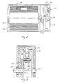
- Fig. 1a designates a piston-cylinder device with a cylinder 2 and a piston 3 displaceable in the cylinder.
- the piston 3 is joined to a piston rod 4, which extends through an opening 5 in one end wall 6 of the cylinder 2.
- the end wall also has a ventilation opening 7.
- the opposite end wall 8 of the cylinder 2 and the piston 3 delimit an expansion chamber 9, in which a pyrotechnic charge 10 with a detonator is placed.
- the charge 10 is designed to be exploded by retardation-sensitive means, which are known per se and not shown in more detail here.
- the cylinder wall in the area of the expansion chamber 9 is made with an opening 11 leading to a valve device 12, through which propellant gas in the expansion chamber can be led out to the environment.
- the valve device 12 (Fig. 1b) has a valve slide 14 displaceable in a housing 13, joined to a rotatable set screw 15 in a threaded bore 16 in the housing.
- the set screw 15 is rotatable with the aid of a servomotor 17, which is controlled by an electronic control unit 18 as a function of signals, firstly, from a weight-sensitive sensor 19, which can be built in to the weight-bearing portion of the vehicle seat (not shown) to register the weight of the person sitting in the seat, and secondly, from a so-called roll-over sensor 20 which senses if the vehicle is about to end up upside-down.
- the sensors 19 and 20 cooperating with the control unit 18 are activated, and the control unit 18, via the servomotor 17, sets the valve slide 14 to a position which is calculated to provide the optimal catch sequence for the occupant.
- the relationship between the occupant's weight and the size of the valve opening can be determined by tests and be stored in the control unit. In general, the valve opening is less the higher the weight. If the roll-over sensor indicates that the vehicle is about to end up upside-down, the control unit 18 closes the valve 12, so that the reel mechanism 28 will be fixed in its pretensioning position by blocking the piston 3.
- the lack of a piston rod opening in the expansion chamber 9 assures that gas cannot leak out and change the position of the piston.
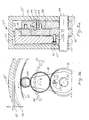
- Fig. 2 shows the planetary gear set 27 and the reel mechanism 28.
- the latter is of a type known per se and has a belt bobbin 30 with a belt web 31 wound up on the bobbin.
- the bobbin has a shaft 32 which, via a web jerk and compartment retardation sensitive retractor mechanism 33 (indicated only schematically here), is joined to a shaft 34 of the planetary gear set 27, which is shown in more detail in Fig. 3a, 3b, 4a and 4b.
- the shaft 34 is rotatably mounted in a housing 35, which is solidly joined, or made in one piece with the housing in which the bobbin shaft 32 is mounted. The housing 35 is thus solidly mounted in the vehicle.
- the planetary gear set shaft 34 carries a sun gear 36, engaging first planet gears 38 carried by a planet carrier 27.
- the planet gears 38 engage second planet gears 39 carried by a second planet carrier.
- the second planet gears 39 engage in turn a toothed rim 40 on the interior of the drum 26, which thus forms the ring gear of the planetary gear set 27.
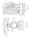
- first blocking means in the form of a spring 41 loaded pin 42 in the end wall of the drum.
- the pin 42 extends into a cavity 43 in the sun gear 36, and thus the ring gear 40 and consequently also the drum can be locked to the sun gear 36 (Figs. 3a and 3b).
- the starting position is the position shown in Figs. 3a and 3b, i.e. the pin 42 locks the sun gear 36 to the ring gear 40, which means a gear ratio of 1:1 between the shaft 34 and the drum 26.
- the pin 42 is kept in the position shown by a cylindrical body 47, which is held in an arcuate groove 48 in the end wall of the drum.
- the retractor mechanism 33 will lock together the shaft 32 of the bobbin and the planetary gear set 34 at the same as the charge 10 in the cylinder expansion chamber 9 is detonated.
- the cable 25, which is joined to and is somewhat wound up on the drum, will now turn the drum an angle which is dependent on the length of stroke of the piston 3 and the diameter of the drum 26.
- the belt web 31 is now pretensioned so that the slack of the web windings on the bobbin 30 is taken up and the belt is tightened against the occupant, the tightening sequence being determined by the setting of the valve 12.
- the torque will be transmitted from the sun gear 36 to the planet gears 38 and 39 and to the planet gear carrier 37, prompting an initial relative movement between the first planet gear 38 and the planet gear carrier 37.
- the pin 45 which during the pretensioning stage was kept with its end inserted into a flanked depression 49 in the first planet gear 38 under the force of the snap-spring 44, will now be pressed towards the planet gear carrier 37, which is provided, along a circle directly opposite the pin, with a plurality of uniformly spaced depressions 46.
- the snap-spring 44 will snap the opposite end of the pin into one of these depressions 46 so that the planet gear carrier 37 will be locked to the housing 35.
- the belt displacement as a function of time for one embodiment of the device according to the invention is illustrated in the diagram in Fig. 6.
- the belt during the pretensioning phase, is pulled in up to 5 cm in circa 15 ms and that the belt is thereafter fed out, during the force-limiting phase, 45 cm in circa 75 ms, which means that the entire belt displacement process takes circa 90 ms and that the gear ratio in the planetary gear set is circa 9:1, if the diameter of the drum and the medium diameter of the fed out web windings from the bobbin are approximately equal.
- the gear set has a housing 50, in which a first shaft 51 is rotatably mounted.
- the shaft 51 carries a planet gear carrier 52, on which first and second planet gears 53 and 54, solidly joined to each other, are mounted.
- a first ring gear 55 disposed on the inside of a drum 56 joined to the cable 25, is joined to a second shaft 57 mounted in the housing.
- the first ring gear 55 engages the first planet gears 53.
- a second ring gear 58 engages the second planet gears 54 and is joined to a sleeve 59, which is mounted concentrically in the housing with the first shaft 51, which is connectable to the belt bobbin shaft with the aid of a belt jerk and passenger compartment retardation-sensitive retractor mechanism (not shown in more detail here).
- blocking means which can be one-way clutches, sawtooth blocking mechanisms or snap-locks of a type known per se
- the first shaft 51 can be locked relative to the second shaft 57 to establish a gear ratio of 1:1
- the second ring gear 58 can be locked to the housing 50, while the shafts 51 and 57 are released relative to each other, thus providing a high gear ratio between the shafts 51 and 57.
- the invention makes possible precision adaption of the catching phase to the weight of the occupant, both during the pretensioning of the belt and force-limiting during the subsequent belt feed-out.
- the possibility of having a long belt feed-out makes it possible to optimize the force-limiting phase.
- the arrangement makes possible a roll-over function by virtue of the fact that the valve can be closed after the pretensioning phase so that the occupant is held securely in his seat.
Abstract
Description
- The present invention relates to a device for pretensioning and force-limiting a safety belt web joined to a reel mechanism in a vehicle, comprising a cylinder, a piston which is displaceable in the cylinder and has a piston rod, which is joined to one side of the piston and extends through an opening in one end wall of the cylinder, a motion-transmitting element acting between the piston rod and the reel mechanism, said element upon displacement of the piston in one direction achieving rotation of the reel mechanism in the winding-up direction of the belt web, a pyrotechnic charge which, when detonated, causes a pressure increase in a cylinder chamber between the piston and a cylinder end wall for displacement of the piston in said one direction.
- Belt pretensioners with force limiters are at present in general use for safety belts in motor vehicles in order to, in a collision, take up the slack between the belt windings on the spool of the reel mechanism and, at the same time, tension up the belt against the body of the occupant, so as to avoid, as much as possible, sliding under the belt or jerking with accompanying whiplash. The force-limiting function, which is achieved by control feeding-out of a predetermined length of the belt after pretensioning, thus reduces the force between the occupant and the belt web up to the point when the occupant must be caught completely by the belt to prevent his head from hitting interior components, e.g. the steering wheel of the vehicle.
- In a previously known design, the force-limiting after pretensioning, when the belt is fed out due to the occupant load on the belt caused by vehicle retardation, is achieved by plastic deformation of a torsion element in the reel mechanism. In practical embodiments, at the desired force level, the maximum possible feed-out length of the belt is limited, by reasons of design, to circa 300 mm. MADYMO simulations with 95 percentile dummy and 35 miles/hour crash velocity have shown that the belt feed-out length should be on the order of 450 mm to achieve optimum effect.
- A purpose of the present invention is to achieve a device of the type described by way of introduction which makes possible, during the force-limiting phase, controlled feed-out of the above described desired belt length of circa 450 mm.
- This is achieved according to the invention by virtue of the fact that the motion-transmitting element is so joined to a ring gear of a planetary gear set that the displacement of the piston in the cylinder results in rotation of the ring gear, and that the planetary gear set is so disposed and coupled to the reel mechanism that the gear ratio between the ring gear and the reel mechanism is 1:1 upon rotation of the ring gear in the winding-up direction of the web and geared up upon rotation in the opposite direction that a movement of the piston over a certain distance in the cylinder corresponds to a several times longer feed-out of the web from the reel mechanism.
- By utilizing a planetary gear set, the desired belt feed-out length can be simply achieved by adapting the gear up of the planetary gear set to the stroke length of the piston and the desired belt feed-out length.
- In a further development of the device according to the invention, said cylinder chamber has an outlet, which communicates with a spill valve which can be set between various degrees of opening and is controlled by a control unit in response to signals from a sensor which senses the weight of the occupant. The degree of opening the valve determines the resistance against the return stroke of the piston during the force-limiting phase, which means that the larger the valve opening is, the less will be the resisting force of the belt against the occupant. By regulating the valve opening in relation to the weight of the occupant, the force limitation is regulated relative to the weight of the occupant.
- In yet a further development of the device according to the invention, the spill valve can be set to a closed position. The control unit is in this case also coordinated with a positional, so-called roll-over sensor, which senses the position of the vehicle. If the sensor indicates that the vehicle is about to end up upside-down after the pretensioning phase, the control unit will close the valve, which means that the occupant will be held securely against the seat and no belt feed-out can occur. To assure that the piston remains in its position when the valve has been closed, in a preferred embodiment said cylinder chamber is delimited between the side of the piston opposite to the piston rod and the second end wall of the cylinder, the motion-transmitting element being arranged to rotate the reel mechanism in the winding-up direction of the belt when the piston is displaced in the protrusion direction of the piston rod. This provides an expansion space without a through-hole for the piston rod, which would otherwise be a potential path for leakage.
- The invention will now be described in more detail below with reference to examples shown in the accompanying drawings, where
- Fig. 1a shows a schematic longitudinal section through one embodiment of a piston-cylinder device with a valve and a motion-transmitting element according to the invention, and Fig. 1b shows an enlargement of the valve in Fig. 1a with associated means for controlling the valve,
- Fig. 2 shows a schematic longitudinal section through a reel mechanism with a first embodiment of a planetary gear set,
- Fig. 3a shows a partial enlargement of the planetary gear set in Fig. 2 with associated blocking means in the pretensioning position, and Fig. 3b shows a schematic side view of the gear set in Fig. 3a,
- Fig. 4a shows a partial enlargement of the planetary gear set in Fig. 2 with associated blocking means in the force-limiting position, and Fig. 4b shows a schematic side view of the gear set in Fig. 4a,
- Fig. 5 shows a schematic longitudinal section through a second embodiment of a planetary gear set,
- Fig. 6 shows a diagram of the web displacement as a function of time during the pretensioning and force-limiting stages.
-
- In Fig. 1a, 1 designates a piston-cylinder device with a
cylinder 2 and apiston 3 displaceable in the cylinder. Thepiston 3 is joined to apiston rod 4, which extends through an opening 5 in one end wall 6 of thecylinder 2. The end wall also has a ventilation opening 7. The opposite end wall 8 of thecylinder 2 and thepiston 3 delimit an expansion chamber 9, in which apyrotechnic charge 10 with a detonator is placed. Thecharge 10 is designed to be exploded by retardation-sensitive means, which are known per se and not shown in more detail here. The cylinder wall in the area of the expansion chamber 9 is made with an opening 11 leading to avalve device 12, through which propellant gas in the expansion chamber can be led out to the environment. - The valve device 12 (Fig. 1b) has a
valve slide 14 displaceable in ahousing 13, joined to arotatable set screw 15 in a threadedbore 16 in the housing. Theset screw 15 is rotatable with the aid of aservomotor 17, which is controlled by anelectronic control unit 18 as a function of signals, firstly, from a weight-sensitive sensor 19, which can be built in to the weight-bearing portion of the vehicle seat (not shown) to register the weight of the person sitting in the seat, and secondly, from a so-called roll-over sensor 20 which senses if the vehicle is about to end up upside-down. - At the end of the
piston rod 4, there is aroller 21, and on either side of thecylinder 2 there are tworollers cable loop 24. The twoparts 24a and 24b of the loop converge in asingle cable 25 which is joined to adrum 26, which, via aplanetary gear set 27, is arranged to drive a reel mechanism (Fig. 2) which is known per se and is generally designated 28, as will be described below. This arrangement with a pushing piston rod instead of a pulling piston rod eliminates one opening in the end wall 8 on the expansion chamber side of thepiston 3. The arrangement with acable loop 24 around the piston assures that there will be a symmetrical load on thepiston rod 4. - When the passenger(s) is(are) seated and the driver turns the ignition key, the
sensors control unit 18 are activated, and thecontrol unit 18, via theservomotor 17, sets thevalve slide 14 to a position which is calculated to provide the optimal catch sequence for the occupant. The relationship between the occupant's weight and the size of the valve opening can be determined by tests and be stored in the control unit. In general, the valve opening is less the higher the weight. If the roll-over sensor indicates that the vehicle is about to end up upside-down, thecontrol unit 18 closes thevalve 12, so that thereel mechanism 28 will be fixed in its pretensioning position by blocking thepiston 3. The lack of a piston rod opening in the expansion chamber 9 assures that gas cannot leak out and change the position of the piston. - Fig. 2 shows the planetary gear set 27 and the
reel mechanism 28. The latter is of a type known per se and has abelt bobbin 30 with abelt web 31 wound up on the bobbin. The bobbin has ashaft 32 which, via a web jerk and compartment retardation sensitive retractor mechanism 33 (indicated only schematically here), is joined to ashaft 34 of theplanetary gear set 27, which is shown in more detail in Fig. 3a, 3b, 4a and 4b. Theshaft 34 is rotatably mounted in ahousing 35, which is solidly joined, or made in one piece with the housing in which thebobbin shaft 32 is mounted. Thehousing 35 is thus solidly mounted in the vehicle. The planetary gear setshaft 34 carries asun gear 36, engagingfirst planet gears 38 carried by aplanet carrier 27. Theplanet gears 38 engagesecond planet gears 39 carried by a second planet carrier. Thesecond planet gears 39 engage in turn atoothed rim 40 on the interior of thedrum 26, which thus forms the ring gear of the planetary gear set 27. With the aid of first blocking means in the form of aspring 41 loadedpin 42 in the end wall of the drum. Thepin 42 extends into acavity 43 in thesun gear 36, and thus thering gear 40 and consequently also the drum can be locked to the sun gear 36 (Figs. 3a and 3b). With the aid of other blocking means in the form of asecond pin 45, loaded by a snap-spring 44 and disposed in a bore in theplanet gear carrier 37, said pin projecting into acavity 46 in thehousing 35, theplanet gear carrier 37 can be locked to the housing (Figs. 4a and 4b). - The starting position is the position shown in Figs. 3a and 3b, i.e. the
pin 42 locks thesun gear 36 to thering gear 40, which means a gear ratio of 1:1 between theshaft 34 and thedrum 26. Thepin 42 is kept in the position shown by acylindrical body 47, which is held in anarcuate groove 48 in the end wall of the drum. In a collision, theretractor mechanism 33 will lock together theshaft 32 of the bobbin and the planetary gear set 34 at the same as thecharge 10 in the cylinder expansion chamber 9 is detonated. Thecable 25, which is joined to and is somewhat wound up on the drum, will now turn the drum an angle which is dependent on the length of stroke of thepiston 3 and the diameter of thedrum 26. Thebelt web 31 is now pretensioned so that the slack of the web windings on thebobbin 30 is taken up and the belt is tightened against the occupant, the tightening sequence being determined by the setting of thevalve 12. - When the
piston 3 has reached its end position in thecylinder 2, the pretensioning is completed and the forces on the belt web change directions as the occupant loads the belt during the retardation. This will also reverse the torque direction in the planetary gear set, thereby initiating the force-limiting stage, which is illustrated in Figs. 4a and 4b. Thus, theshaft 34 with thesun gear 36 begins to rotate in a direction opposite to the original pretensioning direction, and thecylindrical body 47, which is held by the friction against thehousing 35 under the influence of thespring 41; is displaced in thegroove 48 to the position shown in Fig. 4b, which means that thespring 41 can move thepin 42 out of thecavity 43, as is shown in Fig. 4a. Thesun gear 36 can now rotate relative to thedrum 26. The torque will be transmitted from thesun gear 36 to the planet gears 38 and 39 and to theplanet gear carrier 37, prompting an initial relative movement between thefirst planet gear 38 and theplanet gear carrier 37. Thepin 45, which during the pretensioning stage was kept with its end inserted into a flankeddepression 49 in thefirst planet gear 38 under the force of the snap-spring 44, will now be pressed towards theplanet gear carrier 37, which is provided, along a circle directly opposite the pin, with a plurality of uniformly spaceddepressions 46. The snap-spring 44 will snap the opposite end of the pin into one of thesedepressions 46 so that theplanet gear carrier 37 will be locked to thehousing 35. There will thereby be a gear ratio between theshaft 34 of the planetary gear set and itsring gear 40, corresponding to the relationship between the number of teeth on thesun gear 36 and thering gear 40. A similar ratio is obtained between the return stroke of the piston and the feed-out length of the belt. The force under which this process occurs is determined by the setting of thevalve 12 and is thus adapted to the weight of the occupant. - The belt displacement as a function of time for one embodiment of the device according to the invention is illustrated in the diagram in Fig. 6. As can be seen from the diagram, the belt, during the pretensioning phase, is pulled in up to 5 cm in circa 15 ms and that the belt is thereafter fed out, during the force-limiting phase, 45 cm in circa 75 ms, which means that the entire belt displacement process takes circa 90 ms and that the gear ratio in the planetary gear set is circa 9:1, if the diameter of the drum and the medium diameter of the fed out web windings from the bobbin are approximately equal.
- In order to obtain a large gear ratio in the planetary gear set, without the diameter of the drum tending to be so large that space problems are created, it is most suitable to arrange the gearing in two steps. One example of such a planetary gear set is shown in Fig. 5. The gear set has a housing 50, in which a first shaft 51 is rotatably mounted. The shaft 51 carries a
planet gear carrier 52, on which first and second planet gears 53 and 54, solidly joined to each other, are mounted. A first ring gear 55, disposed on the inside of a drum 56 joined to thecable 25, is joined to a second shaft 57 mounted in the housing. The first ring gear 55 engages the first planet gears 53. A second ring gear 58 engages the second planet gears 54 and is joined to asleeve 59, which is mounted concentrically in the housing with the first shaft 51, which is connectable to the belt bobbin shaft with the aid of a belt jerk and passenger compartment retardation-sensitive retractor mechanism (not shown in more detail here). With the aid of blocking means (not shown in more detail here), which can be one-way clutches, sawtooth blocking mechanisms or snap-locks of a type known per se, during the pretensioning phase the first shaft 51 can be locked relative to the second shaft 57 to establish a gear ratio of 1:1, and, during the force-limiting phase, the second ring gear 58 can be locked to the housing 50, while the shafts 51 and 57 are released relative to each other, thus providing a high gear ratio between the shafts 51 and 57. - The invention makes possible precision adaption of the catching phase to the weight of the occupant, both during the pretensioning of the belt and force-limiting during the subsequent belt feed-out. The possibility of having a long belt feed-out makes it possible to optimize the force-limiting phase. Finally, the arrangement makes possible a roll-over function by virtue of the fact that the valve can be closed after the pretensioning phase so that the occupant is held securely in his seat.
Claims (8)
- Device for pretensioning and force-limiting a safety belt web (31) joined to a reel mechanism (28) in a vehicle, comprising a cylinder (2), a piston (3) which is displaceable in the cylinder and has a piston rod (4), which is joined to one side of the piston and extends through an opening (5) in one end wall (6) of the cylinder, a motion-transmitting element (24, 25) acting between the piston rod and the reel mechanism, said element upon displacement of the piston in one direction achieving rotation of the reel mechanism in the winding-up direction of the belt web, a pyrotechnic charge (10) which, when detonated, causes a pressure increase in a cylinder chamber (9) between the piston and a cylinder end wall (8) for displacement of the piston in said one direction, said motion-transmitting element (24, 25) being so joined to a ring gear (40, 55) of a planetary gear set (27; 50), that displacement of the piston (3) in the cylinder (2) results in rotation of the ring gear, and that the planetary gear set is so disposed and coupled to the reel mechanism (28) that the gear ratio between the ring gear and the reel mechanism is 1:1 upon rotation of the ring gear in the winding-up direction of the web, characterized in that the planetary gear set is so disposed that the gear ratio between the ring gear and the reel mechanism is higher when rotating in the opposite direction, whereby the return movement of the piston over a certain distance in the cylinder corresponds to a several times longer feed-out of the web (31) from the reel mechanism.
- Device according to claim 1, characterized in that the motion-transmitting element (24, 25) is elongated and flexible and is joined to and partially wound up on a drum (26; 56), which is solidly joined to the ring gear (40, 55) of the planetary gear set.
- Device according to claim 2, characterized in that the inside of the drum (26) forms a ring gear (40) of a planetary gear set, which has a sun gear (36) with a shaft (34), which can be coupled together with a shaft (32) in the reel mechanism (28), and that blocking means (42, 45) are arranged which, upon rotation of the drum in the winding-up direction of the reel mechanism, lock the drum and the sun gear together and which, upon rotation in the opposite direction, release the sun gear from the drum and block the planet gear carrier of the planetary gear set against rotation.
- Device according to claim 2, characterized in that the inside of the drum (56) forms a ring gear (55), which engages first planet gears (53) on a planet gear carrier (52), which can be coupled together with a shaft (32) in the reel mechanism (28), that second planet gears (54) on the planet gear carrier are solidly joined to the first planet gears and engage a second ring gear (58), and that blocking means are arranged which, upon rotation of the drum in the winding-up direction of the reel mechanism, lock the drum and the planet gear carrier together and which, upon rotation of the drum in the opposite direction, release the drum from the planet gear carrier and block the second ring gear against rotation.
- Device according to one of claims 1 - 4, characterized in that said cylinder chamber (9) has an outlet (11), which communicates with a spill valve (12), which can be set between various degrees of opening.
- Device according to claim 5, characterized in that the spill valve (12) is continuously adjustable between various degrees of opening and a closed position.
- Device according to claim 6, characterized in that the spill valve (12) has a valve element (14) which can be set by a servo unit (17), which is controlled by a control unit (18) as a function of signals from a sensor (19) which senses the weight of the occupant.
- Device according to claim 7, characterized in that said cylinder chamber (9) is delimited between the side of the piston (3) opposite to the piston rod and the second end wall (8) of the cylinder, that the motion-transmitting element (24, 25) is disposed to rotate the reel mechanism (28) in the winding-up direction of the belt web, when the piston is displaced in the protruding direction of the piston rod (4), that the control unit (18) is coordinated with a positional sensor (20) which senses the position of the vehicle, and that the control unit is arranged to close the spill valve upon a signal from the positional sensor indicating that the vehicle is about to end up upside-down.
Applications Claiming Priority (2)
| Application Number | Priority Date | Filing Date | Title |
|---|---|---|---|
| SE0003682A SE523268C2 (en) | 2000-10-12 | 2000-10-12 | Seat belt tensioner and force limiter |
| SE0003682 | 2000-10-12 |
Publications (3)
| Publication Number | Publication Date |
|---|---|
| EP1197404A2 true EP1197404A2 (en) | 2002-04-17 |
| EP1197404A3 EP1197404A3 (en) | 2004-03-03 |
| EP1197404B1 EP1197404B1 (en) | 2005-09-07 |
Family
ID=20281388
Family Applications (1)
| Application Number | Title | Priority Date | Filing Date |
|---|---|---|---|
| EP01850168A Expired - Lifetime EP1197404B1 (en) | 2000-10-12 | 2001-10-10 | Safety belt pretensioner and force limiter |
Country Status (4)
| Country | Link |
|---|---|
| US (1) | US6585295B2 (en) |
| EP (1) | EP1197404B1 (en) |
| DE (1) | DE60113208T2 (en) |
| SE (1) | SE523268C2 (en) |
Families Citing this family (7)
| Publication number | Priority date | Publication date | Assignee | Title |
|---|---|---|---|---|
| CN2680521Y (en) * | 2004-01-02 | 2005-02-23 | 陈小华 | Safety belt in loose contact with human body |
| US7159478B2 (en) * | 2004-04-14 | 2007-01-09 | Takata Seat Belts Inc. | Pretensioner testing apparatus and method |
| CN102303580B (en) * | 2011-06-28 | 2013-07-10 | 常州博万达汽车安全设备有限公司 | Pre-tensioner used for safety seat belt |
| DE102012019004B4 (en) * | 2012-09-27 | 2022-06-02 | Zf Automotive Germany Gmbh | Belt retractor for a safety belt |
| JP2019206224A (en) * | 2018-05-28 | 2019-12-05 | Joyson Safety Systems Japan株式会社 | Seat belt retractor and seat belt device |
| CN115104448B (en) * | 2022-06-08 | 2023-04-18 | 浙江师范大学 | Chain saw with automatically tensioned chain |
| DE102022118796A1 (en) | 2022-07-27 | 2024-02-01 | Audi Aktiengesellschaft | Restraint device for securing an occupant of a motor vehicle during a collision situation, seating device for a motor vehicle and motor vehicle |
Family Cites Families (7)
| Publication number | Priority date | Publication date | Assignee | Title |
|---|---|---|---|---|
| DE3231509C2 (en) * | 1982-08-25 | 1985-04-18 | Daimler-Benz Ag, 7000 Stuttgart | Tensioning device for a belt end of a seat belt system that can be wound onto a belt roll |
| DE3400177A1 (en) * | 1984-01-04 | 1985-07-25 | Autoflug Gmbh, 2084 Rellingen | Device for tightening safety belts |
| DE4319273A1 (en) * | 1993-06-09 | 1994-12-15 | Trw Repa Gmbh | Belt retractors for vehicle seat belt systems |
| JP3322773B2 (en) * | 1994-07-06 | 2002-09-09 | エヌエスケー・オートリブ株式会社 | Seat belt retractor with pretensioner |
| JPH0966801A (en) * | 1995-08-31 | 1997-03-11 | Tokai Rika Co Ltd | Gear mechanism and pretentioner |
| JP4467688B2 (en) * | 1999-01-19 | 2010-05-26 | タカタ株式会社 | Seat belt retractor |
| US6340176B1 (en) * | 2000-03-31 | 2002-01-22 | Delphi Technologies, Inc. | Seat restraint tensioner |
-
2000
- 2000-10-12 SE SE0003682A patent/SE523268C2/en not_active IP Right Cessation
-
2001
- 2001-10-10 EP EP01850168A patent/EP1197404B1/en not_active Expired - Lifetime
- 2001-10-10 DE DE60113208T patent/DE60113208T2/en not_active Expired - Lifetime
- 2001-10-12 US US09/682,752 patent/US6585295B2/en not_active Expired - Lifetime
Non-Patent Citations (1)
| Title |
|---|
| None |
Also Published As
| Publication number | Publication date |
|---|---|
| EP1197404A3 (en) | 2004-03-03 |
| DE60113208T2 (en) | 2006-03-23 |
| SE523268C2 (en) | 2004-04-06 |
| US6585295B2 (en) | 2003-07-01 |
| US20020056984A1 (en) | 2002-05-16 |
| SE0003682L (en) | 2002-04-13 |
| EP1197404B1 (en) | 2005-09-07 |
| SE0003682D0 (en) | 2000-10-12 |
| DE60113208D1 (en) | 2005-10-13 |
Similar Documents
| Publication | Publication Date | Title |
|---|---|---|
| KR102092755B1 (en) | Seat belt pretensioning retractor assembly | |
| US5839686A (en) | Chain driven pretensioner and retractor | |
| US7475840B2 (en) | Method for controlling a seat belt retractor | |
| EP1265774B1 (en) | Seat belt retractor | |
| EP1477377A1 (en) | Webbing retractor | |
| EP3517373B1 (en) | Seatbelt pretensioning retractor assembly | |
| EP1276647B1 (en) | Seat belt retractor | |
| US5782423A (en) | Spiral tube compact pretensioner and retractor | |
| US7581757B2 (en) | Retractor with pretensioner | |
| CN110520336A (en) | Safety belt prefastening including piston relief valve member furls device assembly | |
| US20100176236A1 (en) | High performance tightener | |
| EP1197404B1 (en) | Safety belt pretensioner and force limiter | |
| EP0842067B1 (en) | Retractor with load limiting spool with decoupled pretensioner | |
| JP6893263B2 (en) | Retractor pretensioner assembly | |
| CN115989163A (en) | Safety belt retractor | |
| EP1201513B1 (en) | Soft-start piston actuator | |
| US20080290203A1 (en) | Electromechanical seat belt retractor | |
| US20020070306A1 (en) | Pretensioner drive | |
| EP1197403B1 (en) | Safety belt pretensioner | |
| JP4153129B2 (en) | Seat belt device | |
| JP2000198413A (en) | Seat belt device | |
| WO2006044953A1 (en) | Adaptive restraint system with retractor having pretensioner | |
| GB2326623A (en) | Pretensioner and comfort device driven by two ratio epicyclic gear. |
Legal Events
| Date | Code | Title | Description |
|---|---|---|---|
| PUAI | Public reference made under article 153(3) epc to a published international application that has entered the european phase |
Free format text: ORIGINAL CODE: 0009012 |
|
| AK | Designated contracting states |
Kind code of ref document: A2 Designated state(s): AT BE CH CY DE DK ES FI FR GB GR IE IT LI LU MC NL PT SE TR |
|
| AX | Request for extension of the european patent |
Free format text: AL;LT;LV;MK;RO;SI |
|
| PUAL | Search report despatched |
Free format text: ORIGINAL CODE: 0009013 |
|
| AK | Designated contracting states |
Kind code of ref document: A3 Designated state(s): AT BE CH CY DE DK ES FI FR GB GR IE IT LI LU MC NL PT SE TR |
|
| AX | Request for extension of the european patent |
Extension state: AL LT LV MK RO SI |
|
| 17P | Request for examination filed |
Effective date: 20040826 |
|
| AKX | Designation fees paid |
Designated state(s): DE FR GB |
|
| GRAP | Despatch of communication of intention to grant a patent |
Free format text: ORIGINAL CODE: EPIDOSNIGR1 |
|
| GRAS | Grant fee paid |
Free format text: ORIGINAL CODE: EPIDOSNIGR3 |
|
| GRAA | (expected) grant |
Free format text: ORIGINAL CODE: 0009210 |
|
| AK | Designated contracting states |
Kind code of ref document: B1 Designated state(s): DE FR GB |
|
| REG | Reference to a national code |
Ref country code: GB Ref legal event code: FG4D |
|
| PGFP | Annual fee paid to national office [announced via postgrant information from national office to epo] |
Ref country code: FR Payment date: 20051006 Year of fee payment: 5 |
|
| REF | Corresponds to: |
Ref document number: 60113208 Country of ref document: DE Date of ref document: 20051013 Kind code of ref document: P |
|
| PLBE | No opposition filed within time limit |
Free format text: ORIGINAL CODE: 0009261 |
|
| STAA | Information on the status of an ep patent application or granted ep patent |
Free format text: STATUS: NO OPPOSITION FILED WITHIN TIME LIMIT |
|
| 26N | No opposition filed |
Effective date: 20060608 |
|
| PG25 | Lapsed in a contracting state [announced via postgrant information from national office to epo] |
Ref country code: FR Free format text: LAPSE BECAUSE OF FAILURE TO SUBMIT A TRANSLATION OF THE DESCRIPTION OR TO PAY THE FEE WITHIN THE PRESCRIBED TIME-LIMIT Effective date: 20061020 |
|
| EN | Fr: translation not filed | ||
| PGFP | Annual fee paid to national office [announced via postgrant information from national office to epo] |
Ref country code: DE Payment date: 20141015 Year of fee payment: 14 Ref country code: GB Payment date: 20141015 Year of fee payment: 14 |
|
| REG | Reference to a national code |
Ref country code: DE Ref legal event code: R119 Ref document number: 60113208 Country of ref document: DE |
|
| GBPC | Gb: european patent ceased through non-payment of renewal fee |
Effective date: 20151010 |
|
| PG25 | Lapsed in a contracting state [announced via postgrant information from national office to epo] |
Ref country code: GB Free format text: LAPSE BECAUSE OF NON-PAYMENT OF DUE FEES Effective date: 20151010 Ref country code: DE Free format text: LAPSE BECAUSE OF NON-PAYMENT OF DUE FEES Effective date: 20160503 |