EP1197374A2 - Joint fastening structure for an automotive power plant fastening portion - Google Patents
Joint fastening structure for an automotive power plant fastening portion Download PDFInfo
- Publication number
- EP1197374A2 EP1197374A2 EP01124123A EP01124123A EP1197374A2 EP 1197374 A2 EP1197374 A2 EP 1197374A2 EP 01124123 A EP01124123 A EP 01124123A EP 01124123 A EP01124123 A EP 01124123A EP 1197374 A2 EP1197374 A2 EP 1197374A2
- Authority
- EP
- European Patent Office
- Prior art keywords
- combustion engine
- internal combustion
- main body
- fastening portion
- accessory
- Prior art date
- Legal status (The legal status is an assumption and is not a legal conclusion. Google has not performed a legal analysis and makes no representation as to the accuracy of the status listed.)
- Granted
Links
Images


Classifications
-
- F—MECHANICAL ENGINEERING; LIGHTING; HEATING; WEAPONS; BLASTING
- F02—COMBUSTION ENGINES; HOT-GAS OR COMBUSTION-PRODUCT ENGINE PLANTS
- F02F—CYLINDERS, PISTONS OR CASINGS, FOR COMBUSTION ENGINES; ARRANGEMENTS OF SEALINGS IN COMBUSTION ENGINES
- F02F7/00—Casings, e.g. crankcases
- F02F7/0043—Arrangements of mechanical drive elements
- F02F7/0046—Shape of casings adapted to facilitate fitting or dismantling of engine parts
-
- F—MECHANICAL ENGINEERING; LIGHTING; HEATING; WEAPONS; BLASTING
- F02—COMBUSTION ENGINES; HOT-GAS OR COMBUSTION-PRODUCT ENGINE PLANTS
- F02B—INTERNAL-COMBUSTION PISTON ENGINES; COMBUSTION ENGINES IN GENERAL
- F02B61/00—Adaptations of engines for driving vehicles or for driving propellers; Combinations of engines with gearing
- F02B61/06—Combinations of engines with mechanical gearing
-
- F—MECHANICAL ENGINEERING; LIGHTING; HEATING; WEAPONS; BLASTING
- F02—COMBUSTION ENGINES; HOT-GAS OR COMBUSTION-PRODUCT ENGINE PLANTS
- F02B—INTERNAL-COMBUSTION PISTON ENGINES; COMBUSTION ENGINES IN GENERAL
- F02B67/00—Engines characterised by the arrangement of auxiliary apparatus not being otherwise provided for, e.g. the apparatus having different functions; Driving auxiliary apparatus from engines, not otherwise provided for
- F02B67/04—Engines characterised by the arrangement of auxiliary apparatus not being otherwise provided for, e.g. the apparatus having different functions; Driving auxiliary apparatus from engines, not otherwise provided for of mechanically-driven auxiliary apparatus
Definitions
- the present invention relates to a joint fastening structure for an automotive power plant fastening portion in which an accessory is jointly fastened to the fastening portion.
- the accessory is secured to the housing at a portion of the internal combustion engine main body which is contiguous with the transmission with threaded components such as bolts and screws, and the housing is fastened to the cylinder block with threaded components.
- the cylinder block and the transmission case are fastened together with threaded components.
- the present invention relates to an improved automotive power plant fastening portion which has overcome the difficulty, and according to a first aspect of the invention, there is provided a joint fastening structure for an automotive power plant fastening portion which is commonly used as a fastening portion of an internal combustion engine main body and a transmission case and a fastening portion of said internal combustion engine main body and an accessory, the joint fastening structure being characterized in that a threaded component passes through the transmission case and the internal combustion engine main body so as to be integrally fastened to internal threads in the accessory.
- the internal combustion engine main body and the transmission case can easily be fastened together without being influenced by the mounting configuration of the accessory to the housing and the other accessories.
- the accessory is jointly fastened to the internal combustion engine and the transmission which constitute the automotive power plant with the threaded component which integrally combines the internal combustion engine with the transmission, the fastening man-hours and number of fastening components can be reduced, and this leads to reduction in cost.
- portions at which the threaded component passes through the transmission case and the internal combustion engine main body are flanges.
- the flange portions of the internal combustion engine main body and the transmission case are highly rigid, in addition to the advantage provided by the first aspect of the invention, there is provided an advantage that the fastening strength can be increased.
- the threaded component is disposed in the vicinity of a mating surface between the cylinder block and the oil pan.
- the threaded component for use in attaching the accessory is allowed to pass through the highly rigid portion in the vicinity of the mating surface between the cylinder block and the oil pan, in addition to the advantages provided in accordance with the first and second aspects of the invention, there is further provided an advantage that the fastening strength of the accessory relative to the internal combustion engine main body and the transmission case can further be increased.
- a cooling water pipe member communicating with a radiator is disposed along the vicinity of the accessory.
- An automotive power plant 1 mounted at a front portion of a vehicle body of a passenger car, not shown, is an in-line four-cylinder four-stroke-cycle engine with DOHC (double overhead camshafts), and as shown in Fig. 1, the automotive power plant 1 comprises an internal combustion engine 2 and a transmission 3.
- a main body of the internal combustion engine 2 a cylinder block 4 and an oil pan 5 are brought into abutment with each other at a mating surface 6, an upper surface of the cylinder block 4 and a lower face of a cylinder head 29 are brought into abutment with each other.
- the cylinder block 4, the oil pan 5 and the cylinder head 29 are combined with each other with bolts or stud bolts which are not shown.
- an end face of a flange 9 of a case of the transmission 3 is brought into abutment with end faces (right end faces as viewed in Fig. 1, or portions of Fig. 3 where many dots are provided and many doted lines are caused to intersect with each other) of a flange 7 of the cylinder block 4 and a flange 8 of the oil pan 5.
- a housing flange 11 of a starter motor 10 is brought into abutment with the other end face (a left end face as viewed in Fig. 1) of the flange 7 of the cylinder block 4.
- a bolt 15 passes through an upper portion of the flange 9 of the case of the transmission 3 from right to left to be fastened into a bolt hole 7b in an upper portion of the flange 7 of the cylinder block 4 (refer to Figs 2 and 3).
- a bolt 16 passes through a bolt hole 8a in a lower portion of the flange 8 of the oil pan 5 (refer to Figs. 2 and 3) from left to right to be fastened into a lower portion of the flange 9 of the case of the transmission 3.
- Bolts, not shown, other than but similar to the bolt 15 or bolt 16 are fastened along the full circumference of the transmission 3 at required intervals.
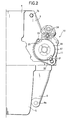
- the housing flange 11 of the starter motor 10 is brought into abutment with a bottom portion 18 of a main body 17 of the starter motor 10 from left, and as shown in Fig. 2, protruding lugs 20 are integrally provided on a top portion 19 of the main body 17 of the starter motor 10 diametrically across the center of the main body 17.
- an externally threaded portion 22 of a machine screw 21 passing through the protruding lug 20 from left to right is fastened into an internally threaded portion 23 of the housing flange 11 of the starter motor 10.
- a magnet switch 24 is integrally assembled the main body 17 of the starter motor 10.
- an air conditioner compressor 25 is integrally mounted on the cylinder block 4 at a position below the lower surface of the cylinder block 4 on a left end side thereof with a mounting member, not shown.
- a cooling water pump 26 is integrally mounted on the cylinder block 4 with a mounting member, not shown, at a position above the air conditioner compressor 25 and on this side of the cylinder block 4 as viewed in Fig. 1.
- an ACG 27, which is an alternate current generator, is integrally mounted on the cylinder block 4 with a mounting member, not shown, at a position above the cooling water pump 26.
- the cooling water pump 26 and an upper right-hand side portion (as viewed in Fig. 1) of the cylinder block 4 are connected to each other via a cooling water pipe 28 so as to provide a communication therebetween, the cooling water pipe 28 being a cooling water pipe member which connects to a radiator, not shown.
- Figs. 1 to 3 The embodiment illustrated in Figs. 1 to 3 is constructed as described above, and at the position where the starter motor 10 is mounted on the cylinder block 4, the housing flange 11 of the starter motor 10 is integrally jointly fastened to the flange 7 of the cylinder block 7 and the flange 9 of the transmission 3 with the bolts 12 which pass through the bolt hole 9a in the flange 9 of the transmission 7 and the bolt hole 7a in the flange 7 of the cylinder block 4 from right to left as viewed in Fig. 1 to be fastened into the internally threaded hole 14 in the housing flange 11 of the starter motor 10. Therefore, the cylinder block 4 and the transmission 3 need to be fastened together with no other bolt, whereby the fastening man-hours and number of fastening bolts can be reduced, this leading to reduction in production costs.
- the bolt 12 is fastened from the transmission 3 side toward the cylinder block 4 side of the internal combustion engine 2, the fastening work of the bolt 12 can easily be implemented without any interference with the starter motor 10, the magnet switch 24 and the cooling water pipe 28.
- the starter motor 10 tends to be heated to a high temperature when receiving heat from the cylinder block 4 which is heated to a high temperature and heat from the atmosphere within the engine compartment, since the temperature of the cooling water in the cooling water pipe 28 is lower than the temperatures of the cylinder block 4 and the starter motor 10 irrespective of the running condition of the internal combustion engine 2, the starter motor 10 is cooled by the cooling water running through the cooling water pipe 28, the durability being thereby increased.
- a joint fastening structure which is commonly used as a fastening portion of an internal combustion engine main body and a transmission case and a fastening portion of the internal combustion engine main body and an accessory, wherein a threaded component passes through the transmission case and the internal combustion engine main body so as to be integrally fastened to internal threads in the accessory.
Landscapes
- Engineering & Computer Science (AREA)
- Chemical & Material Sciences (AREA)
- Combustion & Propulsion (AREA)
- Mechanical Engineering (AREA)
- General Engineering & Computer Science (AREA)
- Cylinder Crankcases Of Internal Combustion Engines (AREA)
- Arrangement Of Transmissions (AREA)
- General Details Of Gearings (AREA)
- Connection Of Plates (AREA)
Abstract
Description
Claims (4)
- A joint fastening structure for an automotive power plant fastening portion, which is commonly used as a fastening portion of an internal combustion engine main body and a transmission case and a fastening portion of said internal combustion engine main body and an accessory, said joint fastening structure characterized in that:a threaded component passes through said transmission case and said internal combustion engine main body so as to be integrally fastened to internal threads in said accessory.
- The joint fastening structure for an automotive power plant fastening portion as set forth in Claim 1, wherein portions at which said threaded component passes through said transmission case and said internal combustion engine main body are flanges.
- The joint fastening structure for an automotive power plant fastening portion as set forth in Claim 1 or 2, wherein said threaded component is disposed in the vicinity of a mating surface between said cylinder block and said oil pan.
- The joint fastening structure for an automotive power plant fastening portion as set forth in any one of Claims 1 to 3, wherein a cooling water pipe member communicating with a radiator is disposed along the vicinity of said accessory.
Applications Claiming Priority (4)
| Application Number | Priority Date | Filing Date | Title |
|---|---|---|---|
| JP2000310093 | 2000-10-11 | ||
| JP2000310093 | 2000-10-11 | ||
| JP2001188111 | 2001-06-21 | ||
| JP2001188111A JP2002187441A (en) | 2000-10-11 | 2001-06-21 | Joint fastening structure at vehicle power plant fastening section |
Publications (3)
| Publication Number | Publication Date |
|---|---|
| EP1197374A2 true EP1197374A2 (en) | 2002-04-17 |
| EP1197374A3 EP1197374A3 (en) | 2003-01-02 |
| EP1197374B1 EP1197374B1 (en) | 2004-09-15 |
Family
ID=26601842
Family Applications (1)
| Application Number | Title | Priority Date | Filing Date |
|---|---|---|---|
| EP01124123A Expired - Lifetime EP1197374B1 (en) | 2000-10-11 | 2001-10-10 | Joint fastening structure for an automotive power plant fastening portion |
Country Status (6)
| Country | Link |
|---|---|
| US (1) | US6591806B2 (en) |
| EP (1) | EP1197374B1 (en) |
| JP (1) | JP2002187441A (en) |
| CN (1) | CN1174164C (en) |
| BR (1) | BR0104493B1 (en) |
| DE (1) | DE60105519T2 (en) |
Families Citing this family (11)
| Publication number | Priority date | Publication date | Assignee | Title |
|---|---|---|---|---|
| JP2005240752A (en) * | 2004-02-27 | 2005-09-08 | Honda Motor Co Ltd | ACG stator mounting structure |
| DE102004010800A1 (en) * | 2004-03-05 | 2005-09-22 | Fev Motorentechnik Gmbh | Internal combustion engine |
| US20070039258A1 (en) * | 2005-08-19 | 2007-02-22 | Walker John R Iii | Adjustable attachment system |
| DE102007051717A1 (en) * | 2007-10-30 | 2009-05-07 | GM Global Technology Operations, Inc., Detroit | unit carrier |
| JP5195632B2 (en) * | 2009-05-13 | 2013-05-08 | トヨタ自動車株式会社 | Power unit fastening structure |
| JP5252311B2 (en) * | 2009-09-25 | 2013-07-31 | スズキ株式会社 | Hybrid vehicle cooling system |
| JP5476357B2 (en) * | 2011-11-18 | 2014-04-23 | 本田技研工業株式会社 | Auxiliary support structure for internal combustion engine |
| US9840143B1 (en) | 2015-05-20 | 2017-12-12 | Hydro-Gear Limited Partnership | Cooling pump assembly and cooling system for utility vehicle |
| US10106027B1 (en) * | 2015-06-01 | 2018-10-23 | Hydro-Gear Limited Partnership | Generator/cooling assembly and system for utility vehicle |
| US10358040B1 (en) | 2015-06-01 | 2019-07-23 | Hydro-Gear Limited Partnership | Drive assembly and system for utility vehicle |
| US10391854B1 (en) | 2015-06-15 | 2019-08-27 | Hydro-Gear Limited Partnership | Drive and cooling system for utility vehicle |
Family Cites Families (14)
| Publication number | Priority date | Publication date | Assignee | Title |
|---|---|---|---|---|
| AT343958B (en) * | 1975-09-04 | 1978-06-26 | List Hans | MULTICYLINDER COMBUSTION ENGINE |
| JPS5949419B2 (en) * | 1980-12-11 | 1984-12-03 | 日産自動車株式会社 | automotive engine |
| US4470379A (en) * | 1981-03-25 | 1984-09-11 | Honda Giken Kogyo Kabushiki Kaisha | Multi-cylinder engine |
| JPH0736117Y2 (en) * | 1988-12-24 | 1995-08-16 | 日産自動車株式会社 | Cylinder block |
| JPH0720376Y2 (en) * | 1989-10-26 | 1995-05-15 | マツダ株式会社 | Engine starter mounting structure |
| DE4206068A1 (en) | 1991-03-01 | 1992-09-03 | Mazda Motor | CONSTRUCTION OF A MOTOR UNIT OF A VEHICLE |
| GB2258011B (en) | 1991-07-24 | 1994-09-14 | Rover Group | A method of assembling an internal combustion engine |
| JP3391102B2 (en) * | 1994-06-30 | 2003-03-31 | スズキ株式会社 | Engine cooling piping structure |
| DE19511864C1 (en) * | 1995-03-31 | 1996-07-25 | Daimler Benz Ag | Internal combustion engine for simplified assembly |
| JPH0968141A (en) * | 1995-08-31 | 1997-03-11 | Denso Corp | Starter support structure |
| JP3423864B2 (en) | 1997-09-12 | 2003-07-07 | 本田技研工業株式会社 | Hybrid vehicle drive |
| JPH11294178A (en) * | 1998-04-03 | 1999-10-26 | Honda Motor Co Ltd | Auxiliary parts mounting structure for in-line multi-cylinder engine |
| DE19818593C2 (en) * | 1998-04-25 | 2000-03-30 | Daimler Chrysler Ag | Crankcase of an internal combustion engine |
| US6223712B1 (en) * | 1999-10-19 | 2001-05-01 | Robert E. Montgomery | Personal watercraft engine |
-
2001
- 2001-06-21 JP JP2001188111A patent/JP2002187441A/en active Pending
- 2001-10-09 US US09/971,714 patent/US6591806B2/en not_active Expired - Fee Related
- 2001-10-10 BR BRPI0104493-1A patent/BR0104493B1/en not_active IP Right Cessation
- 2001-10-10 EP EP01124123A patent/EP1197374B1/en not_active Expired - Lifetime
- 2001-10-10 DE DE60105519T patent/DE60105519T2/en not_active Expired - Lifetime
- 2001-10-11 CN CNB011412569A patent/CN1174164C/en not_active Expired - Fee Related
Also Published As
| Publication number | Publication date |
|---|---|
| DE60105519D1 (en) | 2004-10-21 |
| US20020050263A1 (en) | 2002-05-02 |
| CN1174164C (en) | 2004-11-03 |
| EP1197374B1 (en) | 2004-09-15 |
| CN1346931A (en) | 2002-05-01 |
| BR0104493A (en) | 2002-05-28 |
| EP1197374A3 (en) | 2003-01-02 |
| JP2002187441A (en) | 2002-07-02 |
| US6591806B2 (en) | 2003-07-15 |
| BR0104493B1 (en) | 2009-05-05 |
| DE60105519T2 (en) | 2005-02-10 |
Similar Documents
| Publication | Publication Date | Title |
|---|---|---|
| US6591806B2 (en) | Joint fastening structure for an automotive power plant fastening portion | |
| US5908017A (en) | Intake system mounting construction of engine | |
| DE69823015D1 (en) | Total cooling assembly for motor vehicles powered by internal combustion engines | |
| US6609491B2 (en) | Multi-cylinder engine and engine auxiliary parts mounting construction | |
| US7100561B2 (en) | Cover for joint part between engine and transmission | |
| EP0514943A2 (en) | Mounting arrangement for automotive engine with longitudinally arranged cylinders | |
| US5979393A (en) | Engine control unit mounting apparatus for motor vehicle | |
| US6435157B1 (en) | Support for an accessory of an internal combustion engine and method of making same | |
| US11293344B2 (en) | Cover member mounting structure for engine | |
| US6712052B2 (en) | Engine control unit | |
| EP0408880B1 (en) | An air intake device for an internal combustion engine | |
| JPH0247243Y2 (en) | ||
| GB2407342A (en) | Multi-cylinder engine electric device mounting construction | |
| EP1087126A2 (en) | Four-stroke cycle engine | |
| JP2001115852A (en) | Engine accessory mounting structure | |
| ATE254719T1 (en) | INTAKE SYSTEM FOR A MOTOR VEHICLE | |
| JP7519383B2 (en) | Notch on cylinder head intake surface for angled installation on engine cylinder head | |
| KR100507143B1 (en) | an ECU mounting structure of vehicles | |
| JPH0252100B2 (en) | ||
| JPH07119483A (en) | Cooler compressor mounting structure for vehicle engine | |
| KR100312549B1 (en) | Air Conditioning Compressor Drive Structure | |
| CN120462124A (en) | Power assembly and vehicle | |
| KR19990004999A (en) | Assembly structure of engine, transmission and oil pan | |
| JPH10129281A (en) | Gearbox for transmission | |
| KR19980037624U (en) | Automotive pipe connection structure |
Legal Events
| Date | Code | Title | Description |
|---|---|---|---|
| PUAI | Public reference made under article 153(3) epc to a published international application that has entered the european phase |
Free format text: ORIGINAL CODE: 0009012 |
|
| AK | Designated contracting states |
Kind code of ref document: A2 Designated state(s): AT BE CH CY DE DK ES FI FR GB GR IE IT LI LU MC NL PT SE TR |
|
| AX | Request for extension of the european patent |
Free format text: AL;LT;LV;MK;RO;SI |
|
| PUAL | Search report despatched |
Free format text: ORIGINAL CODE: 0009013 |
|
| AK | Designated contracting states |
Kind code of ref document: A3 Designated state(s): AT BE CH CY DE DK ES FI FR GB GR IE IT LI LU MC NL PT SE TR |
|
| AX | Request for extension of the european patent |
Free format text: AL;LT;LV;MK;RO;SI |
|
| 17P | Request for examination filed |
Effective date: 20030314 |
|
| AKX | Designation fees paid |
Designated state(s): DE FR GB |
|
| 17Q | First examination report despatched |
Effective date: 20030926 |
|
| GRAP | Despatch of communication of intention to grant a patent |
Free format text: ORIGINAL CODE: EPIDOSNIGR1 |
|
| RIC1 | Information provided on ipc code assigned before grant |
Ipc: 7B 60K 17/04 A Ipc: 7F 02F 7/00 B Ipc: 7F 02B 61/06 B |
|
| GRAS | Grant fee paid |
Free format text: ORIGINAL CODE: EPIDOSNIGR3 |
|
| GRAA | (expected) grant |
Free format text: ORIGINAL CODE: 0009210 |
|
| AK | Designated contracting states |
Kind code of ref document: B1 Designated state(s): DE FR GB |
|
| REG | Reference to a national code |
Ref country code: GB Ref legal event code: FG4D |
|
| REG | Reference to a national code |
Ref country code: IE Ref legal event code: FG4D |
|
| REF | Corresponds to: |
Ref document number: 60105519 Country of ref document: DE Date of ref document: 20041021 Kind code of ref document: P |
|
| ET | Fr: translation filed | ||
| PLBE | No opposition filed within time limit |
Free format text: ORIGINAL CODE: 0009261 |
|
| STAA | Information on the status of an ep patent application or granted ep patent |
Free format text: STATUS: NO OPPOSITION FILED WITHIN TIME LIMIT |
|
| 26N | No opposition filed |
Effective date: 20050616 |
|
| PGFP | Annual fee paid to national office [announced via postgrant information from national office to epo] |
Ref country code: DE Payment date: 20091008 Year of fee payment: 9 |
|
| PGFP | Annual fee paid to national office [announced via postgrant information from national office to epo] |
Ref country code: FR Payment date: 20091029 Year of fee payment: 9 Ref country code: GB Payment date: 20091007 Year of fee payment: 9 |
|
| GBPC | Gb: european patent ceased through non-payment of renewal fee |
Effective date: 20101010 |
|
| PG25 | Lapsed in a contracting state [announced via postgrant information from national office to epo] |
Ref country code: FR Free format text: LAPSE BECAUSE OF NON-PAYMENT OF DUE FEES Effective date: 20101102 |
|
| REG | Reference to a national code |
Ref country code: FR Ref legal event code: ST Effective date: 20110630 |
|
| PG25 | Lapsed in a contracting state [announced via postgrant information from national office to epo] |
Ref country code: GB Free format text: LAPSE BECAUSE OF NON-PAYMENT OF DUE FEES Effective date: 20101010 |
|
| REG | Reference to a national code |
Ref country code: DE Ref legal event code: R119 Ref document number: 60105519 Country of ref document: DE Effective date: 20110502 |
|
| PG25 | Lapsed in a contracting state [announced via postgrant information from national office to epo] |
Ref country code: DE Free format text: LAPSE BECAUSE OF NON-PAYMENT OF DUE FEES Effective date: 20110502 |