EP1197372B1 - Motorized vehicle with air intake - Google Patents
Motorized vehicle with air intake Download PDFInfo
- Publication number
- EP1197372B1 EP1197372B1 EP01203877A EP01203877A EP1197372B1 EP 1197372 B1 EP1197372 B1 EP 1197372B1 EP 01203877 A EP01203877 A EP 01203877A EP 01203877 A EP01203877 A EP 01203877A EP 1197372 B1 EP1197372 B1 EP 1197372B1
- Authority
- EP
- European Patent Office
- Prior art keywords
- air intake
- air
- fresh
- armour plate
- duct
- Prior art date
- Legal status (The legal status is an assumption and is not a legal conclusion. Google has not performed a legal analysis and makes no representation as to the accuracy of the status listed.)
- Expired - Lifetime
Links
- 238000011144 upstream manufacturing Methods 0.000 claims description 6
- 206010041662 Splinter Diseases 0.000 claims description 5
- 238000001816 cooling Methods 0.000 claims description 3
- 238000002485 combustion reaction Methods 0.000 description 3
- 238000001514 detection method Methods 0.000 description 1
- 239000000446 fuel Substances 0.000 description 1
- 239000000463 material Substances 0.000 description 1
- 230000001681 protective effect Effects 0.000 description 1
- 238000004080 punching Methods 0.000 description 1
- 238000001931 thermography Methods 0.000 description 1
Images
Classifications
-
- B—PERFORMING OPERATIONS; TRANSPORTING
- B60—VEHICLES IN GENERAL
- B60K—ARRANGEMENT OR MOUNTING OF PROPULSION UNITS OR OF TRANSMISSIONS IN VEHICLES; ARRANGEMENT OR MOUNTING OF PLURAL DIVERSE PRIME-MOVERS IN VEHICLES; AUXILIARY DRIVES FOR VEHICLES; INSTRUMENTATION OR DASHBOARDS FOR VEHICLES; ARRANGEMENTS IN CONNECTION WITH COOLING, AIR INTAKE, GAS EXHAUST OR FUEL SUPPLY OF PROPULSION UNITS IN VEHICLES
- B60K11/00—Arrangement in connection with cooling of propulsion units
- B60K11/08—Air inlets for cooling; Shutters or blinds therefor
-
- B—PERFORMING OPERATIONS; TRANSPORTING
- B60—VEHICLES IN GENERAL
- B60K—ARRANGEMENT OR MOUNTING OF PROPULSION UNITS OR OF TRANSMISSIONS IN VEHICLES; ARRANGEMENT OR MOUNTING OF PLURAL DIVERSE PRIME-MOVERS IN VEHICLES; AUXILIARY DRIVES FOR VEHICLES; INSTRUMENTATION OR DASHBOARDS FOR VEHICLES; ARRANGEMENTS IN CONNECTION WITH COOLING, AIR INTAKE, GAS EXHAUST OR FUEL SUPPLY OF PROPULSION UNITS IN VEHICLES
- B60K13/00—Arrangement in connection with combustion air intake or gas exhaust of propulsion units
- B60K13/02—Arrangement in connection with combustion air intake or gas exhaust of propulsion units concerning intake
-
- B—PERFORMING OPERATIONS; TRANSPORTING
- B60—VEHICLES IN GENERAL
- B60Y—INDEXING SCHEME RELATING TO ASPECTS CROSS-CUTTING VEHICLE TECHNOLOGY
- B60Y2200/00—Type of vehicle
- B60Y2200/20—Off-Road Vehicles
- B60Y2200/24—Military vehicles
Definitions
- the present invention relates to a motorized vehicle, in accordance with the preamble of claim 1.
- the air intake In a combat vehicle driven by a combustion engine, in order to protect an air intake ballistically and at the same time to obtain a signature adjustment of same with respect to IR, i.e. to give the air intake a low IR signature, the air intake has previously been designed as an approximately 7-cm thick screen consisting of labyrinthine profiles which form air intake openings, so-called ballistic screens, which prevent direct viewing into the fresh-air duct and thus make it difficult to detect by IR a heat-generating engine situated near the air intake.
- ballistic screens are very heavy and complicated to produce.
- US-5 628 682 discloses a previously known ballistically protective air intake for an armoured vehicle.
- US-3 428 141 discloses a motorized vehicle comprising a ballistically protected air intake, wherein a heat-emitting source in the vehicle is placed in immediate proximity to the air intake, whereby the air intake comprises a perforated armour plate lying level with an outer bodywork plate of the vehicle and a fresh-air duct which adjoins the inside of the perforated armour plate, the air intake further having a fan for sucking the fresh air necessary for running the vehicle into the duct via air intake openings in the armour plate, and the fresh-air duct having an airflow-deflecting wall section situated between the air intake openings in the armour plate and the heat-emitting source,
- An object of the present invention is to make available a motorized vehicle with a ballistically protected and signature-secured air intake where a perforated armour plate has a low height and weight and also a low signature with respect to both RR and IR.
- said vehicle according to the invention is characterized by the features of claim 1.
- the design of the wall section means that it can be kept cooled during vehicle operation, this makes it difficult to detect by IR cameras, and at the same time the perforation openings in the plate can be punched out easily as straight small holes in a relatively thin-walled armour plate with a thickness of only about 5 to 10 mm.
- Said airflow-deflecting wall section can here be designed as a double wall with an air bypass duct in between, where one wall part of the double wall can be of anti-splinter design, preferably made of armour plate.
- the air bypass duct is preferably connected upstream to a fresh-air intake and connected downstream to the fresh-air duct upstream of the fan.
- a fine-mesh net with a mesh width of about 2 to 5 mm is preferably placed over the air intake openings in the armour plate.
- a ballistically protected fresh-air intake according to the invention for a motorized combat vehicle is designated in general by reference number 10.
- the air intake comprises a plane perforated armour plate 12 lying level with an outer, preferably upper bodywork plate 14 of the vehicle.
- the armour plate 12 has a thickness of about 5 to 10 mm, which permits simple punching out of air intake openings 16 with a diameter of the same order of size as the thickness of the plate 12.
- a fresh-air duct 18 Adjoining the inside of the perforated plate 12 is a fresh-air duct 18 in which a fan 20 (shown diagrammatically) can suck fresh air into the vehicle in order to provide it with air for the combustion of the fuel and for cooling of the engine (cooler 21) and possibly supply air to the crew areas.
- the duct 18 is angled immediately inside the perforated armour plate 12 by means of a wall section 22 which is situated between the plate 12 and a heat-emitting source, in this case a combustion engine 24.
- a heat-emitting source in this case a combustion engine 24.
- the bypass duct 26 can be formed by a double wall consisting of an inner wall element 28 and an outer wall element 30, the latter preferably being made of armour plate or other suitable anti-splinter material so that in the event of damage to the air intake 10 it will strengthen the fresh-air duct 18 and intercept splinters.
- the upstream end of the bypass duct 26 can open into one or more intake openings 32 in the perforated armour plate 12 or into a separate intake at a distance from the plate 12, while the downstream end 34 of the duct 26 opens into the fresh-air duct 18 upstream of the fan 20, so that the latter can also suck cooling air into the bypass duct 26 in order to keep the wall section 22, and in particular the wall element 28 facing towards the perforated armour plate 12, cool and thus minimize the IR signature of the air intake which will otherwise be created by the adjacent heat-emitting engine 24.
- a fine-mesh net 36 (mesh width about 2 to 5 mm) is placed on the outside of and over the air intake openings 16, 32, as is shown in Figure 2.
Landscapes
- Engineering & Computer Science (AREA)
- Chemical & Material Sciences (AREA)
- Combustion & Propulsion (AREA)
- Transportation (AREA)
- Mechanical Engineering (AREA)
- Cooling, Air Intake And Gas Exhaust, And Fuel Tank Arrangements In Propulsion Units (AREA)
- Motor Or Generator Cooling System (AREA)
- Exhaust Silencers (AREA)
- Measuring Temperature Or Quantity Of Heat (AREA)
- Superstructure Of Vehicle (AREA)
- Aiming, Guidance, Guns With A Light Source, Armor, Camouflage, And Targets (AREA)
Abstract
Description
- The present invention relates to a motorized vehicle, in accordance with the preamble of
claim 1. - In a combat vehicle driven by a combustion engine, in order to protect an air intake ballistically and at the same time to obtain a signature adjustment of same with respect to IR, i.e. to give the air intake a low IR signature, the air intake has previously been designed as an approximately 7-cm thick screen consisting of labyrinthine profiles which form air intake openings, so-called ballistic screens, which prevent direct viewing into the fresh-air duct and thus make it difficult to detect by IR a heat-generating engine situated near the air intake. Such ballistic screens are very heavy and complicated to produce. For example,
US-5 628 682 discloses a previously known ballistically protective air intake for an armoured vehicle. -
US-3 428 141 discloses a motorized vehicle comprising a ballistically protected air intake, wherein a heat-emitting source in the vehicle is placed in immediate proximity to the air intake, whereby the air intake comprises a perforated armour plate lying level with an outer bodywork plate of the vehicle and a fresh-air duct which adjoins the inside of the perforated armour plate, the air intake further having a fan for sucking the fresh air necessary for running the vehicle into the duct via air intake openings in the armour plate, and the fresh-air duct having an airflow-deflecting wall section situated between the air intake openings in the armour plate and the heat-emitting source, - An object of the present invention is to make available a motorized vehicle with a ballistically protected and signature-secured air intake where a perforated armour plate has a low height and weight and also a low signature with respect to both RR and IR. For this purpose, said vehicle according to the invention is characterized by the features of
claim 1. - Since the design of the wall section means that it can be kept cooled during vehicle operation, this makes it difficult to detect by IR cameras, and at the same time the perforation openings in the plate can be punched out easily as straight small holes in a relatively thin-walled armour plate with a thickness of only about 5 to 10 mm.
- Said airflow-deflecting wall section can here be designed as a double wall with an air bypass duct in between, where one wall part of the double wall can be of anti-splinter design, preferably made of armour plate.
- The air bypass duct is preferably connected upstream to a fresh-air intake and connected downstream to the fresh-air duct upstream of the fan.
- To obtain a good RR signature on the outside of the perforated armour plate, a fine-mesh net with a mesh width of about 2 to 5 mm is preferably placed over the air intake openings in the armour plate.
- The invention will be described in more detail below with reference to the attached drawing.
-
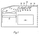
- Figure 1 is a diagrammatic side view of a ballistically protected and signature-adapted air intake according to the invention for a motorized combat vehicle; and
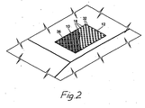
- Figure 2 is a cutaway perspective plan view of the air intake in Figure 1, with a fine-mesh net placed over the air intake openings in the armour plate.
- In Figure 1, a ballistically protected fresh-air intake according to the invention for a motorized combat vehicle is designated in general by
reference number 10. The air intake comprises a plane perforatedarmour plate 12 lying level with an outer, preferablyupper bodywork plate 14 of the vehicle. Thearmour plate 12 has a thickness of about 5 to 10 mm, which permits simple punching out ofair intake openings 16 with a diameter of the same order of size as the thickness of theplate 12. - Adjoining the inside of the
perforated plate 12 is a fresh-air duct 18 in which a fan 20 (shown diagrammatically) can suck fresh air into the vehicle in order to provide it with air for the combustion of the fuel and for cooling of the engine (cooler 21) and possibly supply air to the crew areas. Theduct 18 is angled immediately inside theperforated armour plate 12 by means of awall section 22 which is situated between theplate 12 and a heat-emitting source, in this case acombustion engine 24. In order to reduce the IR signature from the air intake, i.e. to make it difficult to detect with the aid of thermal imaging cameras directed towards thewall section 22 exposed via theair intake openings 16, it is later provided with at least oneair bypass duct 26 which is designed to cool thewall section 22 to a temperature which gives a low IR signature. Thebypass duct 26 can be formed by a double wall consisting of aninner wall element 28 and anouter wall element 30, the latter preferably being made of armour plate or other suitable anti-splinter material so that in the event of damage to theair intake 10 it will strengthen the fresh-air duct 18 and intercept splinters. - The upstream end of the
bypass duct 26 can open into one ormore intake openings 32 in theperforated armour plate 12 or into a separate intake at a distance from theplate 12, while thedownstream end 34 of theduct 26 opens into the fresh-air duct 18 upstream of thefan 20, so that the latter can also suck cooling air into thebypass duct 26 in order to keep thewall section 22, and in particular thewall element 28 facing towards theperforated armour plate 12, cool and thus minimize the IR signature of the air intake which will otherwise be created by the adjacent heat-emittingengine 24. - In order also to minimize the RR signature of the
air intake 10 and reduce the risk of detection by radar, a fine-mesh net 36 (mesh width about 2 to 5 mm) is placed on the outside of and over theair intake openings
Claims (8)
- Motorized vehicle comprising a ballistically protected air intake (10) having a low radar and IR signature, wherein a heat-emitting source (24) in the vehicle is placed in immediate proximity to the air intake (10), and whereby the air intake (10) comprises a perforated armour plate (12) lying level with an outer bodywork plate (14) of the vehicle and a fresh-air duct (18) which adjoins the inside of the perforated armour plate (12), the air intake (10) further having a fan (20) for sucking the fresh air necessary for running the vehicle into the duct (18) via air intake openings (16) in the armour plate (12), and the fresh-air duct (18) having an airflow-deflecting wall section (22) situated between the air intake openings (16) in the armour plate (12) and the heat-emitting source (24), which wall section (22) is provided with at least one air bypass duct (26) for cooling the wall section (22).
- Motorized vehicle according to Claim 1, characterized in that the airflow-deflecting wall section (22) is configured as a double wall (28, 30) with an air bypass duct (26) lying in between.
- Motorized vehicle according to Claim 2, characterized in that one wall part (30) of the double wall is of anti-splinter design, preferably made of armour plate.
- Motorized vehicle according to Claim 3, characterized in that the wall part (30) of the double wall facing away from the fresh-air duct (18) is of anti-splinter design, preferably made of armour plate.
- Motorized vehicle according to any of Claims 1 to 4, characterized in that the air bypass duct (26) is connected upstream to a fresh-air intake (32) and downstream (34) to the fresh-air duct (18) upstream of the fan (20).
- Motorized vehicle according to any of Claims 1 to 5, characterized in that the perforated armour plate (12) has a thickness of about 5 to 10 mm and air intake openings (16) with a diameter substantially identical in size to the thickness.
- Motorized vehicle according to any of Claims 1 to 6, characterized in that a fine-mesh net (36) is placed over the air intake openings (16) in the armour plate (12).
- Motorized vehicle according to Claim 7, characterized in that the net (36) has a mesh width of about 2 to 5 mm.
Applications Claiming Priority (2)
| Application Number | Priority Date | Filing Date | Title |
|---|---|---|---|
| SE0003767A SE517425C2 (en) | 2000-10-18 | 2000-10-18 | Air intake for a motor vehicle |
| SE0003767 | 2000-10-18 |
Publications (3)
| Publication Number | Publication Date |
|---|---|
| EP1197372A2 EP1197372A2 (en) | 2002-04-17 |
| EP1197372A3 EP1197372A3 (en) | 2005-11-09 |
| EP1197372B1 true EP1197372B1 (en) | 2008-01-02 |
Family
ID=20281463
Family Applications (1)
| Application Number | Title | Priority Date | Filing Date |
|---|---|---|---|
| EP01203877A Expired - Lifetime EP1197372B1 (en) | 2000-10-18 | 2001-10-15 | Motorized vehicle with air intake |
Country Status (7)
| Country | Link |
|---|---|
| US (1) | US6662892B2 (en) |
| EP (1) | EP1197372B1 (en) |
| AT (1) | ATE382499T1 (en) |
| DE (1) | DE60132150T2 (en) |
| DK (1) | DK1197372T3 (en) |
| ES (1) | ES2296702T3 (en) |
| SE (1) | SE517425C2 (en) |
Families Citing this family (29)
| Publication number | Priority date | Publication date | Assignee | Title |
|---|---|---|---|---|
| US6937181B2 (en) * | 1999-12-23 | 2005-08-30 | Forsvarets Materielverk | Device for reducing the signature of hot exhausting gases |
| US6485640B2 (en) * | 2001-04-18 | 2002-11-26 | Gary Fout | Flow diverter and exhaust blower for vibrating screen separator assembly |
| US20040216934A1 (en) * | 2003-01-27 | 2004-11-04 | Kubota Corporation | Working vehicle having a hood |
| DE10308084B4 (en) * | 2003-02-26 | 2008-07-31 | Dr. Ing. H.C. F. Porsche Aktiengesellschaft | Cooling device for a motor vehicle drive unit |
| US7086656B2 (en) * | 2004-02-17 | 2006-08-08 | General Motors Corporation | Extendable vehicle step assembly |
| US20050224267A1 (en) * | 2004-04-08 | 2005-10-13 | Callas James J | Cooling system for a vehicular engine |
| SE530178C2 (en) * | 2004-10-27 | 2008-03-18 | Atlas Copco Rock Drills Ab | drill rigs |
| JP2007153072A (en) * | 2005-12-02 | 2007-06-21 | Toyoda Gosei Co Ltd | Duct device |
| JP4175398B2 (en) * | 2006-06-30 | 2008-11-05 | コベルコ建機株式会社 | Exhaust structure of construction machinery |
| US7383905B2 (en) * | 2006-08-07 | 2008-06-10 | Deere & Company | Vehicle cooling system |
| US7861822B2 (en) * | 2006-08-29 | 2011-01-04 | Caterpillar Inc | Engine noise reduction apparatus |
| JP4594942B2 (en) * | 2007-01-16 | 2010-12-08 | コベルコ建機株式会社 | Construction machine cooling structure |
| US7712577B2 (en) * | 2007-03-02 | 2010-05-11 | Gm Global Technology Operations, Inc. | Air induction housing having a perforated sound attenuation wall |
| US8006626B2 (en) * | 2007-05-07 | 2011-08-30 | General Electric Company | System and method for cooling a battery |
| US8720344B2 (en) * | 2007-05-07 | 2014-05-13 | General Electric Company | Thermal management system and method |
| US7694660B2 (en) * | 2008-03-28 | 2010-04-13 | Gm Global Technology Operations, Inc. | Air induction housing having a perforated wall and interfacing sound attenuation chamber |
| US20090314241A1 (en) * | 2008-06-18 | 2009-12-24 | Gm Global Technology Operations, Inc. | Air induction housing having an auxiliary tuning volume for enhancing attenuation and broadening the bandwidth of a primary sound attenuator |
| US20100301638A1 (en) * | 2009-05-29 | 2010-12-02 | Hinshaw Eric J | Integrated Air Intake System |
| US8651800B2 (en) | 2010-06-04 | 2014-02-18 | Gm Global Technology Operations Llp | Induction system with air flow rotation and noise absorber for turbocharger applications |
| US8418790B2 (en) * | 2011-09-20 | 2013-04-16 | Deere & Company | Cooling package baffle or ducting |
| CA2779475C (en) * | 2012-05-29 | 2015-04-07 | Macdon Industries Ltd. | Windrower tractor with parallel heat exchangers for cooling of engine and associated fluids |
| RU2542678C1 (en) * | 2013-10-15 | 2015-02-20 | Открытое акционерное общество "Конструкторское бюро приборостроения им. академика А.Г. Шипунова" | Combat vehicle |
| KR101511053B1 (en) * | 2014-01-23 | 2015-04-10 | 김광수 | Ventilation of hygienic carriage container for livestock |
| JP6246009B2 (en) * | 2014-02-13 | 2017-12-13 | 株式会社神戸製鋼所 | Engine hood |
| EP3173537B1 (en) * | 2014-03-31 | 2019-03-27 | Komatsu Ltd. | Engine compartment of a work vehicle |
| DE102014118800A1 (en) * | 2014-12-17 | 2016-06-23 | Dr. Ing. H.C. F. Porsche Aktiengesellschaft | Bug of a motor vehicle |
| CN105564221A (en) * | 2015-11-09 | 2016-05-11 | 徐工集团工程机械股份有限公司 | Heat-dissipation air channel structure of power compartment and engineering vehicle |
| DK179524B1 (en) * | 2017-03-09 | 2019-02-06 | Inventilate Holding Aps | A MOBILE LEISURE ACCOMMODATION VEHICLE AND A METHOD FOR VENTILATING A MOBILE LEISURE ACCOMMODATION VEHICLE |
| US11718245B2 (en) | 2021-07-29 | 2023-08-08 | Cnh Industrial America Llc | Noise mitigation hood |
Family Cites Families (25)
| Publication number | Priority date | Publication date | Assignee | Title |
|---|---|---|---|---|
| US2473281A (en) * | 1945-03-15 | 1949-06-14 | Eaton Mfg Co | Ventilating and heating apparatus for vehicles |
| DE1455760B2 (en) * | 1965-12-23 | 1976-04-22 | Kühlvorrichtung für ein gepanzertes Fahrzeug Dr.Ing.h.c. F. Porsche AG, 7000 Stuttgart | COOLING DEVICE FOR AN ARMORED VEHICLE |
| US3358787A (en) * | 1966-03-03 | 1967-12-19 | Caterpillar Tractor Co | Engine enclosure |
| JPS5214494B2 (en) * | 1973-08-14 | 1977-04-22 | ||
| DE2437995A1 (en) * | 1974-08-07 | 1976-02-26 | Int Harvester Co | MOTOR VEHICLE |
| US3978938A (en) * | 1975-06-05 | 1976-09-07 | International Harvester Company | Combined airflow with front mounted fuel tank |
| US4071009A (en) * | 1976-06-28 | 1978-01-31 | Caterpillar Tractor Co. | Combined noise suppressing and air flow guide enclosure for engines |
| US4086976A (en) * | 1977-02-02 | 1978-05-02 | International Harvester Company | Isolated clean air chamber and engine compartment in a tractor vehicle |
| US4385678A (en) * | 1979-02-23 | 1983-05-31 | Cederbaum Jerzy H | Silent-running internal combustion motor power unit |
| US4341277A (en) * | 1980-06-23 | 1982-07-27 | Fiat-Allis Construction Machinery, Inc. | Perforated hood with air scoop |
| US4492282A (en) * | 1980-08-28 | 1985-01-08 | Cadillac Gage Company | Six-wheel armored vehicle |
| FR2539038A1 (en) * | 1983-01-06 | 1984-07-13 | Sedems | Anti-fire protection device for an engine compartment, in particular of a motor vehicle |
| EP0122254B1 (en) * | 1983-04-08 | 1987-06-10 | AVL Gesellschaft für Verbrennungskraftmaschinen und Messtechnik mbH.Prof.Dr.Dr.h.c. Hans List | Automotive vehicle |
| US4606422A (en) * | 1985-03-06 | 1986-08-19 | Deere & Company | Cooling air delivery systems |
| US4689060A (en) * | 1986-05-22 | 1987-08-25 | Paccar, Inc. | Cab engine air intake system and method |
| FR2677933B1 (en) * | 1991-06-20 | 1996-05-31 | Giat Ind Sa | METHOD AND DEVICE FOR COOLING BATTERIES IN A VEHICLE EQUIPPED WITH A HEAT ENGINE. |
| JPH0688524A (en) * | 1992-09-08 | 1994-03-29 | Kubota Corp | Engine part structure of farm working vehicle |
| US5628682A (en) * | 1993-06-17 | 1997-05-13 | The U.S. Government As Represented By The Secretary Of The Army | Ballistically protective air passage |
| US5681075A (en) * | 1994-03-17 | 1997-10-28 | Toyoda Gosei Co., Ltd. | Cowl louver |
| JP3676853B2 (en) * | 1994-08-03 | 2005-07-27 | コーニンクレッカ フィリップス エレクトロニクス エヌ ヴィ | MR method for determining nuclear magnetization distribution by surface coil arrangement |
| JPH08119146A (en) * | 1994-10-24 | 1996-05-14 | Kubota Corp | Work vehicle |
| US5709175A (en) * | 1995-12-19 | 1998-01-20 | Caterpillar Inc. | Cooling air system for an engine |
| US6167976B1 (en) * | 1998-07-30 | 2001-01-02 | Deere & Company | Engine enclosure |
| FR2782480B1 (en) * | 1998-08-24 | 2000-10-20 | Solvay | DEVICE AND METHOD FOR EXHAUSTING CALORIES FROM A COMPARTMENT |
| US6026768A (en) * | 1998-09-30 | 2000-02-22 | Honda Giken Kogyo Kabushiki Kaisha | Heat deflection system for a lawn tractor |
-
2000
- 2000-10-18 SE SE0003767A patent/SE517425C2/en not_active IP Right Cessation
-
2001
- 2001-10-15 AT AT01203877T patent/ATE382499T1/en active
- 2001-10-15 DE DE60132150T patent/DE60132150T2/en not_active Expired - Lifetime
- 2001-10-15 ES ES01203877T patent/ES2296702T3/en not_active Expired - Lifetime
- 2001-10-15 EP EP01203877A patent/EP1197372B1/en not_active Expired - Lifetime
- 2001-10-15 DK DK01203877T patent/DK1197372T3/en active
- 2001-10-18 US US09/978,674 patent/US6662892B2/en not_active Expired - Lifetime
Also Published As
| Publication number | Publication date |
|---|---|
| US20020088655A1 (en) | 2002-07-11 |
| DE60132150T2 (en) | 2008-05-08 |
| DK1197372T3 (en) | 2008-05-19 |
| ATE382499T1 (en) | 2008-01-15 |
| SE0003767L (en) | 2002-04-19 |
| ES2296702T3 (en) | 2008-05-01 |
| EP1197372A2 (en) | 2002-04-17 |
| DE60132150D1 (en) | 2008-02-14 |
| US6662892B2 (en) | 2003-12-16 |
| EP1197372A3 (en) | 2005-11-09 |
| SE0003767D0 (en) | 2000-10-18 |
| SE517425C2 (en) | 2002-06-04 |
Similar Documents
| Publication | Publication Date | Title |
|---|---|---|
| US6662892B2 (en) | Air intake for a motorized vehicle | |
| US4186817A (en) | Air inlet for armored car | |
| US8347994B2 (en) | Tractor hood airflow system | |
| GB2176247A (en) | Exhaust system | |
| US20110085300A1 (en) | Communications cabinet with projectile resistant vents | |
| US6405630B1 (en) | Foraminous ballistic grill | |
| US6385968B1 (en) | Exhaust discharge system with low IR signature | |
| US4463653A (en) | Method and apparatus for protecting vehicles against reconnaissance by IR-IMAGING equipment | |
| US5753847A (en) | Grille armor applique' | |
| SI9400309A (en) | Ventilation system for resident part of armoured car | |
| US9097170B2 (en) | Engine | |
| US9777681B2 (en) | Cold air intake circulating air jacket | |
| EP1867514B1 (en) | Air guide in vehicle engine bay | |
| EP1574809B1 (en) | Multispectral camouflage arrangement | |
| US7025165B2 (en) | Device to reduce the visible and infrared signature of a military vehicle | |
| US6099247A (en) | Fan shroud for internal combustion engine | |
| US4499865A (en) | Integral engine cooling system | |
| US6102791A (en) | Cooling-air outlet for a vehicle | |
| JP3319952B2 (en) | Engine lubricant cooling system | |
| EP4311922B1 (en) | Engine assembly, particularly for operating machines | |
| JP2921373B2 (en) | Engine compartment structure | |
| DE102017206889B4 (en) | Sound-absorbing engine cover and V-engine with a sound-absorbing engine cover | |
| AU2017286092B2 (en) | Vehicle having an engine-cooling system | |
| RU98104870A (en) | MILITARY FENCING OF ENTRANCE OPTICS OF THE THERMAL VISION SIGHT | |
| GB2319758A (en) | Radiator with integral combustion air intake openings |
Legal Events
| Date | Code | Title | Description |
|---|---|---|---|
| PUAI | Public reference made under article 153(3) epc to a published international application that has entered the european phase |
Free format text: ORIGINAL CODE: 0009012 |
|
| AK | Designated contracting states |
Kind code of ref document: A2 Designated state(s): AT BE CH CY DE DK ES FI FR GB GR IE IT LI LU MC NL PT SE TR |
|
| AX | Request for extension of the european patent |
Free format text: AL;LT;LV;MK;RO;SI |
|
| PUAL | Search report despatched |
Free format text: ORIGINAL CODE: 0009013 |
|
| AK | Designated contracting states |
Kind code of ref document: A3 Designated state(s): AT BE CH CY DE DK ES FI FR GB GR IE IT LI LU MC NL PT SE TR |
|
| AX | Request for extension of the european patent |
Extension state: AL LT LV MK RO SI |
|
| RIC1 | Information provided on ipc code assigned before grant |
Ipc: 7B 60H 1/30 B Ipc: 7B 60K 13/02 A Ipc: 7F 41H 7/03 B Ipc: 7B 60K 11/08 B |
|
| 17P | Request for examination filed |
Effective date: 20060310 |
|
| RAP1 | Party data changed (applicant data changed or rights of an application transferred) |
Owner name: BAE SYSTEMS HAEGGLUNDS AKTIEBOLAG |
|
| AKX | Designation fees paid |
Designated state(s): AT BE CH CY DE DK ES FI FR GB GR IE IT LI LU MC NL PT SE TR |
|
| 17Q | First examination report despatched |
Effective date: 20060623 |
|
| RTI1 | Title (correction) |
Free format text: MOTORIZED VEHICLE WITH AIR INTAKE |
|
| GRAP | Despatch of communication of intention to grant a patent |
Free format text: ORIGINAL CODE: EPIDOSNIGR1 |
|
| GRAS | Grant fee paid |
Free format text: ORIGINAL CODE: EPIDOSNIGR3 |
|
| GRAA | (expected) grant |
Free format text: ORIGINAL CODE: 0009210 |
|
| AK | Designated contracting states |
Kind code of ref document: B1 Designated state(s): AT BE CH CY DE DK ES FI FR GB GR IE IT LI LU MC NL PT SE TR |
|
| REG | Reference to a national code |
Ref country code: GB Ref legal event code: FG4D |
|
| REG | Reference to a national code |
Ref country code: IE Ref legal event code: FG4D |
|
| REG | Reference to a national code |
Ref country code: CH Ref legal event code: EP |
|
| REF | Corresponds to: |
Ref document number: 60132150 Country of ref document: DE Date of ref document: 20080214 Kind code of ref document: P |
|
| REG | Reference to a national code |
Ref country code: CH Ref legal event code: NV Representative=s name: ARNOLD & SIEDSMA AG |
|
| REG | Reference to a national code |
Ref country code: ES Ref legal event code: FG2A Ref document number: 2296702 Country of ref document: ES Kind code of ref document: T3 |
|
| REG | Reference to a national code |
Ref country code: DK Ref legal event code: T3 |
|
| ET | Fr: translation filed | ||
| PG25 | Lapsed in a contracting state [announced via postgrant information from national office to epo] |
Ref country code: PT Free format text: LAPSE BECAUSE OF FAILURE TO SUBMIT A TRANSLATION OF THE DESCRIPTION OR TO PAY THE FEE WITHIN THE PRESCRIBED TIME-LIMIT Effective date: 20080602 |
|
| PG25 | Lapsed in a contracting state [announced via postgrant information from national office to epo] |
Ref country code: SE Free format text: LAPSE BECAUSE OF FAILURE TO SUBMIT A TRANSLATION OF THE DESCRIPTION OR TO PAY THE FEE WITHIN THE PRESCRIBED TIME-LIMIT Effective date: 20080402 |
|
| PLBE | No opposition filed within time limit |
Free format text: ORIGINAL CODE: 0009261 |
|
| STAA | Information on the status of an ep patent application or granted ep patent |
Free format text: STATUS: NO OPPOSITION FILED WITHIN TIME LIMIT |
|
| 26N | No opposition filed |
Effective date: 20081003 |
|
| PG25 | Lapsed in a contracting state [announced via postgrant information from national office to epo] |
Ref country code: MC Free format text: LAPSE BECAUSE OF NON-PAYMENT OF DUE FEES Effective date: 20081031 |
|
| PG25 | Lapsed in a contracting state [announced via postgrant information from national office to epo] |
Ref country code: CY Free format text: LAPSE BECAUSE OF FAILURE TO SUBMIT A TRANSLATION OF THE DESCRIPTION OR TO PAY THE FEE WITHIN THE PRESCRIBED TIME-LIMIT Effective date: 20080102 |
|
| PG25 | Lapsed in a contracting state [announced via postgrant information from national office to epo] |
Ref country code: IE Free format text: LAPSE BECAUSE OF NON-PAYMENT OF DUE FEES Effective date: 20081015 |
|
| PG25 | Lapsed in a contracting state [announced via postgrant information from national office to epo] |
Ref country code: LU Free format text: LAPSE BECAUSE OF NON-PAYMENT OF DUE FEES Effective date: 20081015 |
|
| PG25 | Lapsed in a contracting state [announced via postgrant information from national office to epo] |
Ref country code: GR Free format text: LAPSE BECAUSE OF FAILURE TO SUBMIT A TRANSLATION OF THE DESCRIPTION OR TO PAY THE FEE WITHIN THE PRESCRIBED TIME-LIMIT Effective date: 20080403 |
|
| PGFP | Annual fee paid to national office [announced via postgrant information from national office to epo] |
Ref country code: BE Payment date: 20121029 Year of fee payment: 12 |
|
| PGFP | Annual fee paid to national office [announced via postgrant information from national office to epo] |
Ref country code: AT Payment date: 20121030 Year of fee payment: 12 |
|
| BERE | Be: lapsed |
Owner name: BAE SYSTEMS HAGGLUNDS A.B. Effective date: 20131031 |
|
| REG | Reference to a national code |
Ref country code: AT Ref legal event code: MM01 Ref document number: 382499 Country of ref document: AT Kind code of ref document: T Effective date: 20131015 |
|
| PG25 | Lapsed in a contracting state [announced via postgrant information from national office to epo] |
Ref country code: AT Free format text: LAPSE BECAUSE OF NON-PAYMENT OF DUE FEES Effective date: 20131015 |
|
| PG25 | Lapsed in a contracting state [announced via postgrant information from national office to epo] |
Ref country code: BE Free format text: LAPSE BECAUSE OF NON-PAYMENT OF DUE FEES Effective date: 20131031 |
|
| REG | Reference to a national code |
Ref country code: FR Ref legal event code: PLFP Year of fee payment: 15 |
|
| PGFP | Annual fee paid to national office [announced via postgrant information from national office to epo] |
Ref country code: DK Payment date: 20151021 Year of fee payment: 15 |
|
| PGFP | Annual fee paid to national office [announced via postgrant information from national office to epo] |
Ref country code: IT Payment date: 20151026 Year of fee payment: 15 |
|
| PGFP | Annual fee paid to national office [announced via postgrant information from national office to epo] |
Ref country code: ES Payment date: 20151021 Year of fee payment: 15 |
|
| REG | Reference to a national code |
Ref country code: FR Ref legal event code: PLFP Year of fee payment: 16 |
|
| REG | Reference to a national code |
Ref country code: DK Ref legal event code: EBP Effective date: 20161031 |
|
| REG | Reference to a national code |
Ref country code: FR Ref legal event code: PLFP Year of fee payment: 17 |
|
| PG25 | Lapsed in a contracting state [announced via postgrant information from national office to epo] |
Ref country code: IT Free format text: LAPSE BECAUSE OF NON-PAYMENT OF DUE FEES Effective date: 20161015 |
|
| PG25 | Lapsed in a contracting state [announced via postgrant information from national office to epo] |
Ref country code: DK Free format text: LAPSE BECAUSE OF NON-PAYMENT OF DUE FEES Effective date: 20161031 |
|
| PGFP | Annual fee paid to national office [announced via postgrant information from national office to epo] |
Ref country code: FI Payment date: 20171020 Year of fee payment: 17 Ref country code: TR Payment date: 20171006 Year of fee payment: 17 Ref country code: FR Payment date: 20171024 Year of fee payment: 17 Ref country code: DE Payment date: 20171019 Year of fee payment: 17 |
|
| PGFP | Annual fee paid to national office [announced via postgrant information from national office to epo] |
Ref country code: CH Payment date: 20171019 Year of fee payment: 17 Ref country code: GB Payment date: 20171019 Year of fee payment: 17 Ref country code: NL Payment date: 20171019 Year of fee payment: 17 |
|
| PG25 | Lapsed in a contracting state [announced via postgrant information from national office to epo] |
Ref country code: ES Free format text: LAPSE BECAUSE OF FAILURE TO SUBMIT A TRANSLATION OF THE DESCRIPTION OR TO PAY THE FEE WITHIN THE PRESCRIBED TIME-LIMIT Effective date: 20080102 |
|
| REG | Reference to a national code |
Ref country code: ES Ref legal event code: FD2A Effective date: 20181121 |
|
| PG25 | Lapsed in a contracting state [announced via postgrant information from national office to epo] |
Ref country code: ES Free format text: LAPSE BECAUSE OF FAILURE TO SUBMIT A TRANSLATION OF THE DESCRIPTION OR TO PAY THE FEE WITHIN THE PRESCRIBED TIME-LIMIT Effective date: 20161016 |
|
| REG | Reference to a national code |
Ref country code: DE Ref legal event code: R119 Ref document number: 60132150 Country of ref document: DE |
|
| REG | Reference to a national code |
Ref country code: CH Ref legal event code: PL |
|
| REG | Reference to a national code |
Ref country code: NL Ref legal event code: MM Effective date: 20181101 |
|
| GBPC | Gb: european patent ceased through non-payment of renewal fee |
Effective date: 20181015 |
|
| PG25 | Lapsed in a contracting state [announced via postgrant information from national office to epo] |
Ref country code: NL Free format text: LAPSE BECAUSE OF NON-PAYMENT OF DUE FEES Effective date: 20181101 Ref country code: FI Free format text: LAPSE BECAUSE OF NON-PAYMENT OF DUE FEES Effective date: 20181015 Ref country code: DE Free format text: LAPSE BECAUSE OF NON-PAYMENT OF DUE FEES Effective date: 20190501 |
|
| PG25 | Lapsed in a contracting state [announced via postgrant information from national office to epo] |
Ref country code: LI Free format text: LAPSE BECAUSE OF NON-PAYMENT OF DUE FEES Effective date: 20181031 Ref country code: FR Free format text: LAPSE BECAUSE OF NON-PAYMENT OF DUE FEES Effective date: 20181031 Ref country code: CH Free format text: LAPSE BECAUSE OF NON-PAYMENT OF DUE FEES Effective date: 20181031 |
|
| PG25 | Lapsed in a contracting state [announced via postgrant information from national office to epo] |
Ref country code: GB Free format text: LAPSE BECAUSE OF NON-PAYMENT OF DUE FEES Effective date: 20181015 |
|
| PG25 | Lapsed in a contracting state [announced via postgrant information from national office to epo] |
Ref country code: TR Free format text: LAPSE BECAUSE OF NON-PAYMENT OF DUE FEES Effective date: 20181015 |