EP1197332A1 - Printing press - Google Patents
Printing press Download PDFInfo
- Publication number
- EP1197332A1 EP1197332A1 EP01123342A EP01123342A EP1197332A1 EP 1197332 A1 EP1197332 A1 EP 1197332A1 EP 01123342 A EP01123342 A EP 01123342A EP 01123342 A EP01123342 A EP 01123342A EP 1197332 A1 EP1197332 A1 EP 1197332A1
- Authority
- EP
- European Patent Office
- Prior art keywords
- cylinder
- sheet
- printing
- inspection
- impression cylinder
- Prior art date
- Legal status (The legal status is an assumption and is not a legal conclusion. Google has not performed a legal analysis and makes no representation as to the accuracy of the status listed.)
- Granted
Links
Images


Classifications
-
- B—PERFORMING OPERATIONS; TRANSPORTING
- B41—PRINTING; LINING MACHINES; TYPEWRITERS; STAMPS
- B41F—PRINTING MACHINES OR PRESSES
- B41F33/00—Indicating, counting, warning, control or safety devices
Definitions
- the present invention relates to a printing press, particularly effective when applied in printing of seals and numbers on stock securities or bank notes.
- FIG. 9 An example of outline structure of a conventional printing press for printing seals and numbers on stock securities or bank notes is shown in Fig. 9.
- a paper feeder 110 has a pile board 111 for stacking up sheets 100 on which patterns have been already printed.
- the paper feeder 110 also includes a feeder board 112 for feeding the sheets 100 on the pile board 111 to a printing unit 120 one by one.
- a swing device 113 is disposed for transferring the sheets 100 to a transfer cylinder 121a.
- the transfer cylinder 121a is opposing an impression cylinder 122a of the printing unit 120 through transfer cylinders 121b, 121c.
- a seal cylinder 123 for printing seals is opposing the impression cylinder 122a.
- a roller group of an ink feeder 124 is opposing the seal cylinder 123.
- Number printing cylinders 125a, 127a for printing numbers are opposing the impression cylinder 122a.
- a roller group of an ink feeder 126a is opposing these number printing cylinders 125a, 127a.
- a transfer cylinder 121d is opposing the impression cylinder 122a.
- An impression cylinder 122b is opposing the transfer cylinder 121d.
- Number printing cylinders 125b, 127b for printing numbers are opposing the impression cylinder 122b.
- a roller group of an ink feeder 126b is opposing these number printing cylinders 125b, 127b.
- a delivery cylinder 129 is opposing the impression cylinder 122b
- a sprocket 131 is coaxially disposed on the delivery cylinder 129.
- a sprocket 132 is provided in a delivery unit 130.
- a delivery chain 133 is stretched between these sprockets 131 and 132.
- Delivery grippers 134 are disposed at specified intervals in the delivery chain 133.
- the delivery unit 130 has piles 135a to 135c for stacking up sheets 100 after printing of seals and numbers.
- the sheets 100 are transferred onto the transfer cylinder 121 from the pile board 111 of the paper feeder 110 through the feeder board 112
- the sheets 100 are transferred to the impression cylinder 122a of the printing unit 120 through the transfer cylinders 121b, 121c, and seals are printed by the seal cylinder 123 and numbers are printed by the number printing cylinders 125a, 127a, and successively they are transferred to the impression cylinder 122b through the transfer cylinder 121d
- numbers are printed by the number printing cylinders 125b, 127b, and they are gripped by the delivery gripper 134 of the delivery unit 130 through the delivery cylinder 129, and conveyed along with running of the delivery chain 133, and discharged onto delivery tables 135a to 135c.
- the printing press of the present invention comprises an impression cylinder for receiving sheet-like object and holding the sheet-like object, a first printing portion for printing the sheet-like object held by the impression cylinder, a second printing portion disposed at transport direction downstream side of the first printing portion for printing the sheet-like object held by the impression cylinder, a number printing portion disposed at transport direction downstream side of the second printing portion for number printing the sheet-like object held by the impression cylinder, and a transport cylinder disposed at transport direction downstream side of the number printing portion for receiving the sheet-like object held by the impression cylinder, in which the distance between the outer circumference portion of the impression cylinder opposing the first printing portion and the outer circumference portion of the impression cylinder opposing the second printing portion and the distance between the outer circumference portion of the impression cylinder opposing the number printing portion and the outer circumference portion of the impression cylinder opposing the transport cylinder are set more than the length in the circumferential direction of the effective printing area of the sheet-like object, the distance between the outer circumference portion of the impression
- This printing press may further comprise an accumulating unit for receiving and accumulating the sheet-like object from the transport cylinder, and a control unit for controlling the number printing portion to stop number printing on the sheet-like object when the sheet-like object do not satisfy the inspection standard on the basis of a signal from the inspecting unit, and controlling the accumulating unit to accumulate in a position different from the sheet-like object satisfying the inspection standard.
- an accumulating unit for receiving and accumulating the sheet-like object from the transport cylinder
- a control unit for controlling the number printing portion to stop number printing on the sheet-like object when the sheet-like object do not satisfy the inspection standard on the basis of a signal from the inspecting unit, and controlling the accumulating unit to accumulate in a position different from the sheet-like object satisfying the inspection standard.
- This printing press may further comprise the inspecting unit which inspects one side and other side of the sheet-like object.
- This printing press may further comprise the inspecting unit which includes a first inspection cylinder rotatably supported, a first inspection camera for inspecting one side of the sheet-like object held in the first inspection cylinder, a second inspection cylinder rotatably supported, and a second inspection camera for inspecting other side of the sheet-like object held in the second inspection cylinder.
- the inspecting unit which includes a first inspection cylinder rotatably supported, a first inspection camera for inspecting one side of the sheet-like object held in the first inspection cylinder, a second inspection cylinder rotatably supported, and a second inspection camera for inspecting other side of the sheet-like object held in the second inspection cylinder.
- This printing press may further comprise the first inspection cylinder and the second inspection cylinder, which can be suction cylinders.
- This printing press may further comprise a first contacting unit for attracting the sheet-like object to the first inspection cylinder side between the feed position for feeding the sheet-like object to the first inspection cylinder and the inspection position of the sheet-like object by the first inspection camera, and a second contacting unit for attracting the sheet-like object to the second inspection cylinder side between the feed position for feeding the sheet-like object to the second inspection cylinder and the inspection position of the sheet-like object by the second inspection camera.
- This printing press may further comprise the first contacting unit and the second contacting unit, which can be brushes.
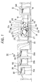
- Fig. 1 is a general outline structural diagram of a printing press
- Fig. 2 is a partially cut-away view of an inspection cylinder
- Fig. 3 is an essential extracted magnified view of a printing unit
- Fig. 4 is a plan view of a sheet
- Fig. 5 is an outline structural diagram of a delivery gripper operation changeover device
- Fig. 6 is a control block diagram of inspection system of printing quality of sheet
- Fig. 7 is a control flowchart of inspection system of printing quality of sheet.
- a paper feeder 10 has a pile board 11.
- the paper feeder 10 also includes a feeder board 12 for feeding the sheets 100 on the pile board 11 to an inspection unit 40 one by one.
- a swing device 13 is disposed for transferring the sheets 100 to a first inspection cylinder 41 of the inspection unit 40.
- the first inspection cylinder 41 includes, as shown in Fig. 2, a central path 41a formed along an axial center of the cylinder 41 in the axial center portion, plural distribution paths 41b formed at specified intervals with respect to the peripheral direction of the cylinder 41 and formed along the axial center direction near the outer circumference portion, a communication path 41c formed between the central path 41a and distribution paths 41b for communicating between them, and plural suction holes 41d formed between the distribution paths 41b and outer circumference portion for communicating between them.
- a suction pump not shown is connected through a rotary joint not shown, and by operating the suction pump, the first inspection cylinder 41 can suck and hold the sheets 100 by way of the central path 41a, communication path 41c, distribution paths 41b, and suction holes 41d. That is, the first inspection cylinder 41 is a suction cylinder.
- a brush 43 as first contacting means, is disposed to slide, so that the sheet 100 held by the first inspection cylinder 41 may be held uniformly on the outer circumference portion of the first inspection cylinder 41.
- a first inspection camera 45 is disposed for checking the printing quality of the sheet 100. This first inspection camera 45 is disposed at a higher position than the axial center position of the first inspection cylinder 41 to prevent contamination of the lens by paper powder and dust as much as possible (in this embodiment, nearly above the first inspection cylinder 41).
- a second inspection cylinder 42 is disposed in an opposing manner, and the second inspection cylinder 42 is composed in the same manner as the first inspection cylinder 41.
- a brush 44 is disposed to slide, so that the sheet 100 held by the second inspection cylinder 42 may be held uniformly on the outer circumference portion of the second inspection cylinder 42.
- a second inspection camera 46 is disposed for checking the printing quality of the sheet 100.
- This second inspection camera 46 is disposed at a higher position than the axial center position of the second inspection cylinder 42 to prevent contamination of the lens by paper powder and dust as much as possible (in this embodiment, nearly at a side position of the second inspection cylinder 42).
- an impression cylinder of the printing unit 20 is provided opposing the cylinder 42 through the transfer cylinders 21a, 21b.
- a seal cylinder 23 for relief printing of seal is provided opposingly to be close to or apart from the impression cylinder 22 (cylinder engagement, disengagement).
- a roller group of ink feeder is opposing this seal cylinder 23.
- a number printing cylinder 25 for printing numbers is provided opposingly to be close to or apart from the impression cylinder 22 (cylinder engagement, disengagement).
- a roller group of ink feeder is opposite this number printing cylinder 25.
- a number printing cylinder 27 for printing numbers is provided opposingly to be close to or apart from the impression cylinder 22 (cylinder engagement, disengagement).
- a roller group of ink feeder, not shown, is opposing this number printing cylinder 27.
- a delivery cylinder 29 for discharging paper is provided in an opposing manner.
- the impression cylinder 22 is a multiple cylinder (a double cylinder in this embodiment) having plural (two in the embodiment) effective impression area for holding the sheets 100 (thick line portions in Fig. 1 and Fig. 3, nearly in the same length as the sheet length of the sheets 100) provided at specific interval along the circumferential direction of the cylinder 22, and gripping grippers are formed between the adjacent effective impression area to form a notch.
- the inspection cylinders 41, 42, transport cylinders 21a, 21b, seal cylinder 23, and number printing cylinders 25, 27 are single cylinders having a single effective impression area and a single notch.
- the distance L 1 between the outer circumference portion of the impression cylinder 22 opposing the seal cylinder 23 and the outer circumference portion of the impression cylinder 22 opposing the number printing cylinder 25 is set longer than the sheet length L o (transfer direction) of the effective printing area 100a of the sheet 100 (L 1 ⁇ L o )
- the distance L 2 between the outer circumference portion of the impression cylinder 22 opposing the number printing cylinder 27 and the outer circumference portion of the impression cylinder 22 opposing the delivery cylinder 29 is set longer than the sheet length L o of the effective printing area 100a of the sheet 100 (L 2 ⁇ L o )
- the distance L 3 between the outer circumference portion of the impression cylinder 22 opposing the seal cylinder 23 and the outer circumference portion of the impression cylinder 22 opposing the number printing cylinder 27 is set shorter than the sum (L a + 2L b ) of the effective impression area length La of the impression cylinder 22 and double of length L b of the notch (L 3 ⁇
- a sprocket 31 is coaxially provided on the delivery cylinder 29.
- a sprocket 32 is provided on the delivery unit 30.
- a delivery chain 33 is stretched between the sprockets 31 and 32.
- Delivery gripper devices 34 are disposed at specific interval in the delivery chain 33.
- the delivery unit 30 comprises conforming sheet discharge tables 35a, 35b for piling up sheets 100 that satisfy the inspection standard (conforming sheet), and a defective sheet discharge table 35c for piling up sheets 100 that do not satisfy the inspection standard (defective sheet).
- a fixed delivery cam 36 for operating the delivery gripper devices 34 is provided at an upper position of the defective sheet discharge table 35c near the delivery chain 33.
- a delivery gripper operation changeover device 50 is provided for changing over presence or absence of operation of the delivery gripper devices 34, and this delivery gripper operation changeover device 50 has a structure as shown in Fig. 5.
- the base end side of an air cylinder 52 is swingably supported.
- end sides of link plates 53, 54 are rotatably coupled.
- Other end side of the link plate 53 is rotatably coupled and supported at the running direction downstream side of the delivery chain 33 at the upper side of the base plate 51.
- one end side of a delivery cam 55 of a plate shape having a cam surface 55a at the lower side is rotatably coupled and supported.
- Other end side of the delivery cam 55 is rotatably coupled and supported at other end side of the link plate 54.
- the delivery gripper device 34 provided in the delivery chain 33, includes a gripper pad 34a supported by the delivery chain 33, a gripper 34b disposed on the gripper pad 34a so as to be free to open and close, a spring, not shown, for moving the gripper 34b in the closing direction, and a cam follower 34c provided integrally with the gripper 34b.
- the cam follower 34c moves while contacting with the cam surface 55a of the delivery cam 55 of the delivery gripper operation changeover device 50, and the gripper 34b opens at a specified position, and when the delivery cam 55 is moved to the retreat position by contracting the rod 52a of the air cylinder 52 of the delivery gripper operation changeover device 50 as mentioned above, along with running and moving of the delivery chain 33, the cam follower 34c directly passes through without contacting with the cam surface 55a of the delivery cam 55 of the delivery gripper operation changeover device 50, and the gripper 34b is kept closed.
- the first inspection camera 45 and second inspection camera 46 are connected to an input portion of a control device 60 which is control means.
- An output portion of the control device 60 is connected to a number printing cylinder engagement and disengagement device 61 (for example, an air cylinder for turning the eccentric bearing for supporting the number printing cylinders 25, 27) for engaging and disengaging the number printing cylinders 25, 27, and the delivery gripper operation changeover device 50. That is, the control device 60 controls the devices 61, 50 on the basis of the signals from the cameras 45, 46 (the detail is described below).
- the seal cylinder 23, ink feeder, and others are combined to compose the first printing portion
- the number printing cylinder 25, ink feeder, number printing cylinder engagement and disengagement device 61, and others compose the second printing portion
- the number printing cylinder 27, ink feeder, number printing cylinder engagement and disengagement device 61, and others compose the number printing portion
- the first and second inspection cylinders 41, 42, brushes 43, 44, first and second inspection cameras 45, 46, suction pump, control device 60, and others compose the inspection means
- the sprockets 31, 32, delivery chain 33, delivery gripper device 34, conforming sheet discharge tables 35a, 35b, defective sheet discharge table 35c, delivery cam 36, delivery gripper operation changeover device 50, and others compose the accumulating means
- the control device 60 and others compose the control means.
- the printing press thus composed, when a sheet 100, on which a pattern is already printed, is transferred from the pile board 11 of the paper feeder 10 to the first inspection cylinder 41 by way of the feeder board 12, the sheet 100 is sucked and held on the outer circumference portion of the first inspection cylinder 41, and is attracted uniformly by the brush 43, and the printing quality of one side (face side) is inspected by the first inspection camera 45, and transferred from the first inspection cylinder 41 to the second inspection cylinder 42.
- the sheet 100 is sucked and held on the outer circumference portion of the second inspection cylinder 42, and is attracted uniformly by the brush 43, and the printing quality of other side (reverse side) is inspected by the second inspection camera 46, and transferred to the transport cylinder 21a.
- the control device 60 evaluates the printing quality of the sheet 100 on the basis of the signals from the inspection cameras 45, 46, and when the printing quality of this sheet 100 satisfies the inspection standard, the number printing cylinder engagement and disengagement device 61 is operated to engage the number printing cylinders 25, 27, and also the air cylinder 52 of the delivery gripper operation changeover device 50 is operated to move the delivery cam 55 of the delivery gripper operation changeover device 50 to the working position.
- the sheet 100 transferred to the transport cylinder 21a is handed over to the impression cylinder 22 of the printing unit 20 through the transport cylinder 21b, and the seal is printed by the seal cylinder 23, and the numbers are printed by the number printing cylinders 25, 27, and the sheet 100 is gripped by the delivery gripper device 34 of the delivery unit 30 through the delivery cylinder 29.
- the distance L 1 between the outer circumference portion of the impression cylinder 22 opposing the seal cylinder 23 and the outer circumference portion of the impression cylinder 22 opposing the number printing cylinder 25 is set longer than the sheet length L o (transfer direction) of the effective printing area 100a of the sheet 100 (L 1 ⁇ L o ), after the seal is printed on the sheet 100 by the seal cylinder 23, the number is printed on this sheet 100 by the number printing cylinder 25. Accordingly, when printing the number by the number printing cylinder 25, it is free from effects of slight vibration at the time of printing by the seal cylinder 23, so that occurrence of wasted paper can be suppressed.
- the distance L 2 between the outer circumference portion of the impression cylinder 22 opposing the number printing cylinder 27 and the outer circumference portion of the impression cylinder 22 opposing the delivery cylinder 29 is set longer than the sheet length L o of the effective printing area 100a of the sheet 100 (L 2 ⁇ L o ), after printing the number on the sheet 100 by the number printing cylinder 27, gripping of the sheet 100 is changed from the impression cylinder 22 to the delivery cylinder 29.
- the terminal end of the sheet 100 is not pulled to the number printing cylinder 27 side by the ink while printing the number, the sheet 100 is securely gripped by the delivery cylinder 29, and also the terminal end of the sheet 100 is not pulled to the delivery cylinder 20 side while printing the number, the number can be printed securely, so that occurrence of wasted paper can be suppressed.
- the distance L 3 between the outer circumference portion of the impression cylinder 22 opposing the seal cylinder 23 and the outer circumference portion of the impression cylinder 22 opposing the number printing cylinder 27 is set shorter than the sum (L a + 2L b ) of the effective impression area length L a of the impression cylinder 22 and double of length L b of the notch (L 3 ⁇ L a + 2L b ), after printing the number on the sheet 100 by the number printing cylinder 27, printing of seal by the seal cylinder 23 on a new sheet 100 is started.
- the number printing cylinder 27 fails to advance the number printing sequence, by immediately throwing off the seal cylinder 23 and number printing cylinders 25, 27 (cylinder disengagement), printing of seal and number is stopped easily, and the second and subsequent sheets 100 from the sheet 100 of wrong number printing are saved.
- On the first sheet from the sheet 100 of wrong number printing printing can be stopped after printing the seal and printing the correct number by the number printing cylinder 25, and therefore after checking and repairing the number printing cylinder 27, the correct number can be printed by the number printing cylinder 27, so that this sheet can be handled as a conforming one, not wasted paper.
- only one sheet 100 of wrong number printing is wasted, so that occurrence of wasted paper is suppressed.
- the cam follower 34c of the delivery gripper device 34 contacts with the cam surface 55a of the delivery cam 55 at the working position of the delivery gripper operation changeover device 50, and the gripper 35b of the delivery gripper device 34 opens, and the sheet is piled up on the conforming sheet discharge table 35a.
- the control device 60 moves the delivery cam 55 of the delivery gripper operation changeover device 50 on the conforming sheet discharge table 35a away to the retreat position, and operates the air cylinder 52 of the delivery gripper operation changeover device 50 to move the delivery cam 55 of the delivery gripper operation changeover device 50 on the conforming sheet discharge table 35b to the working position, thereby changing over the delivery of conforming sheets 100 from the conforming sheet discharge table 35a to the conforming sheet discharge table 35b.
- the sheet 100 on the conforming sheet discharge table 35a can be delivered.
- control device 60 operates the number printing cylinder engagement and disengagement device 61 to disengage the number printing cylinders 25, 27 (to move to the retreat position), and operates the air cylinder 52 of the delivery gripper operation changeover device 50 to move the delivery cam 55 of the delivery gripper operation changeover device 50 to the retreat position.
- the sheet 100 transferred to the transport cylinder 21a is handed over to the impression cylinder 22 of the printing unit 20 through the transport cylinder 21b, and the seal is printed by the seal cylinder 23, but the number printing cylinders 25, 27 are disengaged (withdrawn to the retreat position), and number printing is stopped, and without printing of number, it is gripped by the delivery gripper device 34 of the delivery unit 30 through the delivery cylinder 29.
- the sheet 100 thus gripped by the delivery gripper device 34 without printing of number is conveyed along with running and moving of the delivery chain 33, and the delivery cam 55 of the delivery gripper operation changeover device 50 is withdrawn to the retreat position, and it is directly carried onto the defective sheet discharge table 35c without being discharged on the conforming sheet discharge table 35a or 35b, and the cam follower 34c of the delivery gripper device 34 contacts with the cam surface of the delivery cam 36, and the gripper 34b of the delivery gripper device 34 is opened, so that it is discharged onto the defective sheet discharge table 35c and piled up at a different position from the conforming sheets 100, and the conforming sheet and defective sheet are clearly distinguished.
- the entire printing press is not increased in size.
- the sheet 100 does not satisfy the printing quality standard, by disengaging the number printing cylinders 25, 27 (moving away to the retreat position), number printing on the sheet 100 is stopped, but number printing on the sheet 100 can be also stopped by stopping the operation of the number printing sequence mechanism of the number printing cylinders 25, 27.
- the seal cylinder 23 while printing the sheets 100, the seal cylinder 23 is always engaged, but if the sheet 100 does not satisfy the printing quality standard, the seal cylinder 23 may be also disengaged together with the number printing cylinders 25, 27.
- the embodiment uses the swing device 13 having the swinging fulcrum at the upper side, but, as shown in Fig. 8, by using a swing device 13 having the swinging fulcrum at the lower side, the sheet 100 can be transferred from the second inspection cylinder 42 to the impression cylinder 22 only by the transport cylinder 21b.
- the seal is directly printed from the relief seal cylinder 23, but offset printing of the seal is also possible from the plate cylinder by way of blanket cylinder.
- the outer circumference portion of the impression cylinder 22 opposing the seal cylinder 23 may be taken into consideration.
- the delivery cylinder 29 is used as the transport cylinder, and the sheet 100 are discharged from the delivery cylinder 29 onto the discharge tables 35a to 35c of the delivery unit 30 through the delivery chain 33, but the transfer cylinder may be used as the transport cylinder, and the sheet-like object may be transferred to the delivery cylinder through one or plural transfer cylinders, or sheet-like object may be transferred to a new printing unit through one or plural transfer cylinders.
- the second printing portion is composed of the number printing cylinder 25, ink feeder, and others, but the second printing portion may be also composed of general plate cylinder for printing ordinary patterns, ink feeder, and others.
- the double impression cylinder 22 is used, but triple or multiple diameter impression cylinder may be also used.
- the angle formed by the line linking the outer circumference portion of the impression cylinder opposing the first printing portion and the axial center of the impression cylinder and the line linking the outer circumference portion of the impression cylinder opposing the number printing portion and the axial center of the impression cylinder is 180 degrees or less.
- brushes 43, 44 are used as first and second contacting means, but the invention is not limited to this example.
- rollers, rolls, or other rotating elements may be also used as the first and second contacting means.
Landscapes
- Inking, Control Or Cleaning Of Printing Machines (AREA)
- Rotary Presses (AREA)
- Press Drives And Press Lines (AREA)
- Supply, Installation And Extraction Of Printed Sheets Or Plates (AREA)
- Separation, Sorting, Adjustment, Or Bending Of Sheets To Be Conveyed (AREA)
Abstract
Description
- The entire disclosure of Japanese Patent Application No.2000-312975 filed on October 13th, 2000 including specification, claims, drawings, and summary is incorporated herein by reference in its entirety.
- The present invention relates to a printing press, particularly effective when applied in printing of seals and numbers on stock securities or bank notes.
- An example of outline structure of a conventional printing press for printing seals and numbers on stock securities or bank notes is shown in Fig. 9.
- As shown in Fig. 9, a
paper feeder 110 has apile board 111 for stacking upsheets 100 on which patterns have been already printed. Thepaper feeder 110 also includes afeeder board 112 for feeding thesheets 100 on thepile board 111 to aprinting unit 120 one by one. At the leading end of thefeeder board 112, aswing device 113 is disposed for transferring thesheets 100 to atransfer cylinder 121a. - The
transfer cylinder 121a is opposing animpression cylinder 122a of theprinting unit 120 throughtransfer cylinders seal cylinder 123 for printing seals is opposing theimpression cylinder 122a. A roller group of anink feeder 124 is opposing theseal cylinder 123. Number printing cylinders 125a, 127a for printing numbers are opposing theimpression cylinder 122a. A roller group of an ink feeder 126a is opposing these number printing cylinders 125a, 127a. Atransfer cylinder 121d is opposing theimpression cylinder 122a. Animpression cylinder 122b is opposing thetransfer cylinder 121d.Number printing cylinders impression cylinder 122b. A roller group of anink feeder 126b is opposing thesenumber printing cylinders delivery cylinder 129 is opposing theimpression cylinder 122b. - A
sprocket 131 is coaxially disposed on thedelivery cylinder 129. Asprocket 132 is provided in adelivery unit 130. Adelivery chain 133 is stretched between thesesprockets Delivery grippers 134 are disposed at specified intervals in thedelivery chain 133. Thedelivery unit 130 has piles 135a to 135c for stacking upsheets 100 after printing of seals and numbers. - In such printing press, when the
sheets 100, on which patterns are already printed, are transferred onto the transfer cylinder 121 from thepile board 111 of thepaper feeder 110 through thefeeder board 112, thesheets 100 are transferred to theimpression cylinder 122a of theprinting unit 120 through thetransfer cylinders seal cylinder 123 and numbers are printed by the number printing cylinders 125a, 127a, and successively they are transferred to theimpression cylinder 122b through thetransfer cylinder 121d, and numbers are printed by thenumber printing cylinders delivery gripper 134 of thedelivery unit 130 through thedelivery cylinder 129, and conveyed along with running of thedelivery chain 133, and discharged onto delivery tables 135a to 135c. - However, such conventional printing press had the following problems.
- (1) Since numbers are printed by the numbering cylinder
125a while printing seals on the
sheets 100 by theseal cylinder 123, printing by theseal cylinder 123 may be slightly deviated by light vibration while number printing by the number printing cylinder 125a, thereby resulting in wasted paper. - (2) Since gripping of
sheets 100 is changed from theimpression cylinders transfer cylinder 121d ordelivery cylinder 129 while printing numbers on thesheets 100 by thenumber printing cylinders 127a, 127b, the terminal end of thesheets 100 may be pulled by thenumber printing cylinders 127a, 127b by the ink while number printing, and gripping failure ofsheets 100 may occur in thetransfer cylinder 121d ordelivery cylinder 129, and thesheets 100 may be dropped, or the terminal end of thesheets 100 may be pulled to thetransfer cylinder 121d side ordelivery cylinder 129 side, and number printing failure or waste of paper may occur. -
- Accordingly, a printing press capable of minimizing such loss of
sheets 100 has been keenly demanded. - To solve the problems, the printing press of the present invention comprises an impression cylinder for receiving sheet-like object and holding the sheet-like object, a first printing portion for printing the sheet-like object held by the impression cylinder, a second printing portion disposed at transport direction downstream side of the first printing portion for printing the sheet-like object held by the impression cylinder, a number printing portion disposed at transport direction downstream side of the second printing portion for number printing the sheet-like object held by the impression cylinder, and a transport cylinder disposed at transport direction downstream side of the number printing portion for receiving the sheet-like object held by the impression cylinder, in which the distance between the outer circumference portion of the impression cylinder opposing the first printing portion and the outer circumference portion of the impression cylinder opposing the second printing portion and the distance between the outer circumference portion of the impression cylinder opposing the number printing portion and the outer circumference portion of the impression cylinder opposing the transport cylinder are set more than the length in the circumferential direction of the effective printing area of the sheet-like object, the distance between the outer circumference portion of the impression cylinder opposing the first printing portion and the outer circumference portion of the impression cylinder opposing the number printing portion is set less than the total length of the length of the effective impression area of the impression cylinder and double length of a notch of the impression cylinder, and an inspecting unit is further provided for inspecting the sheet-like object supplied to the impression cylinder.
- This printing press may further comprise an accumulating unit for receiving and accumulating the sheet-like object from the transport cylinder, and a control unit for controlling the number printing portion to stop number printing on the sheet-like object when the sheet-like object do not satisfy the inspection standard on the basis of a signal from the inspecting unit, and controlling the accumulating unit to accumulate in a position different from the sheet-like object satisfying the inspection standard.
- This printing press may further comprise the inspecting unit which inspects one side and other side of the sheet-like object.
- This printing press may further comprise the inspecting unit which includes a first inspection cylinder rotatably supported, a first inspection camera for inspecting one side of the sheet-like object held in the first inspection cylinder, a second inspection cylinder rotatably supported, and a second inspection camera for inspecting other side of the sheet-like object held in the second inspection cylinder.
- This printing press may further comprise the first inspection cylinder and the second inspection cylinder, which can be suction cylinders.
- This printing press may further comprise a first contacting unit for attracting the sheet-like object to the first inspection cylinder side between the feed position for feeding the sheet-like object to the first inspection cylinder and the inspection position of the sheet-like object by the first inspection camera, and
a second contacting unit for attracting the sheet-like object to the second inspection cylinder side between the feed position for feeding the sheet-like object to the second inspection cylinder and the inspection position of the sheet-like object by the second inspection camera. - This printing press may further comprise the first contacting unit and the second contacting unit, which can be brushes.
- The present invention will become more fully understood from the detailed description given hereinbelow and the accompanying drawings which are given by way of illustration only, and thus are not limitative of the present invention, and wherein:
- Fig. 1 is a general outline structural diagram of a printing press applied to an embodiment for printing seals and numbers on stock securities or bank notes;
- Fig. 2 is a partially cut-away view of an inspection cylinder in Fig. 1;
- Fig. 3 is an essential extracted magnified view of a printing unit in Fig. 1;
- Fig. 4 is a plan view of a sheet;
- Fig. 5 is an outline structural diagram of a delivery gripper operation changeover device;
- Fig. 6 is a control block diagram of inspection system of printing quality of sheet;
- Fig. 7 is a control flowchart of inspection system of printing quality of sheet;
- Fig. 8 is a general outline structural diagram of a printing press applied in other embodiment for printing seals and numbers on stock securities or bank notes; and
- Fig. 9 is a general outline structural diagram of a printing press of a related art.
-
- An embodiment of the printing press of the invention applied in printing of seals and numbers on stock securities and bank notes is explained by referring to Fig. 1 to Fig. 7. Fig. 1 is a general outline structural diagram of a printing press, Fig. 2 is a partially cut-away view of an inspection cylinder, Fig. 3 is an essential extracted magnified view of a printing unit, Fig. 4 is a plan view of a sheet, Fig. 5 is an outline structural diagram of a delivery gripper operation changeover device, Fig. 6 is a control block diagram of inspection system of printing quality of sheet, and Fig. 7 is a control flowchart of inspection system of printing quality of sheet.
- As shown in Fig. 1, a
paper feeder 10 has a pile board 11. Thepaper feeder 10 also includes afeeder board 12 for feeding thesheets 100 on the pile board 11 to aninspection unit 40 one by one. At the leading end of thefeeder board 12, aswing device 13 is disposed for transferring thesheets 100 to afirst inspection cylinder 41 of theinspection unit 40. - The
first inspection cylinder 41 includes, as shown in Fig. 2, acentral path 41a formed along an axial center of thecylinder 41 in the axial center portion,plural distribution paths 41b formed at specified intervals with respect to the peripheral direction of thecylinder 41 and formed along the axial center direction near the outer circumference portion, acommunication path 41c formed between thecentral path 41a anddistribution paths 41b for communicating between them, andplural suction holes 41d formed between thedistribution paths 41b and outer circumference portion for communicating between them. At the shaft end side of thecentral path 41a of thefirst inspection cylinder 41, a suction pump not shown is connected through a rotary joint not shown, and by operating the suction pump, thefirst inspection cylinder 41 can suck and hold thesheets 100 by way of thecentral path 41a,communication path 41c,distribution paths 41b, andsuction holes 41d. That is, thefirst inspection cylinder 41 is a suction cylinder. - At the transport direction downstream side with respect to the transfer position of the
sheet 100 with theswing device 13 of thefirst inspection cylinder 41, abrush 43, as first contacting means, is disposed to slide, so that thesheet 100 held by thefirst inspection cylinder 41 may be held uniformly on the outer circumference portion of thefirst inspection cylinder 41. At the transport direction downstream side of thesheet 100 with respect to the sliding position of thebrush 43 on thefirst inspection cylinder 41, afirst inspection camera 45 is disposed for checking the printing quality of thesheet 100. Thisfirst inspection camera 45 is disposed at a higher position than the axial center position of thefirst inspection cylinder 41 to prevent contamination of the lens by paper powder and dust as much as possible (in this embodiment, nearly above the first inspection cylinder 41). - At the transport direction downstream side of the
sheet 100 with respect to the confronting position against thefirst inspection camera 45 of thefirst inspection cylinder 41, asecond inspection cylinder 42 is disposed in an opposing manner, and thesecond inspection cylinder 42 is composed in the same manner as thefirst inspection cylinder 41. At the transport direction downstream side of thesheet 100 with respect to the confronting position against thefirst inspection cylinder 41 of thesecond inspection cylinder 42, abrush 44, as second contacting means, is disposed to slide, so that thesheet 100 held by thesecond inspection cylinder 42 may be held uniformly on the outer circumference portion of thesecond inspection cylinder 42. At the transport direction downstream side of thesheet 100 with respect to the sliding position of thebrush 44 on thesecond inspection cylinder 42, asecond inspection camera 46 is disposed for checking the printing quality of thesheet 100. Thissecond inspection camera 46 is disposed at a higher position than the axial center position of thesecond inspection cylinder 42 to prevent contamination of the lens by paper powder and dust as much as possible (in this embodiment, nearly at a side position of the second inspection cylinder 42). - At the transport direction downstream side of the
sheet 100 with respect to the confronting position of thesecond inspection camera 46 of thesecond inspection cylinder 42 an impression cylinder of theprinting unit 20 is provided opposing thecylinder 42 through thetransfer cylinders 21a, 21b. - At the transport direction downstream side of the
sheet 100 with respect to the confronting position of thetransport cylinder 21b of theimpression cylinder 22, aseal cylinder 23 for relief printing of seal is provided opposingly to be close to or apart from the impression cylinder 22 (cylinder engagement, disengagement). A roller group of ink feeder ,not shown, is opposing thisseal cylinder 23. At the transport direction downstream side of thesheet 100 with respect to the confronting position of theseal cylinder 23 of theimpression cylinder 22, anumber printing cylinder 25 for printing numbers is provided opposingly to be close to or apart from the impression cylinder 22 (cylinder engagement, disengagement). A roller group of ink feeder ,not shown, is opposite thisnumber printing cylinder 25. At the transport direction downstream side of thesheet 100 with respect to the confronting position of thenumber printing cylinder 25 of theimpression cylinder 22, anumber printing cylinder 27 for printing numbers is provided opposingly to be close to or apart from the impression cylinder 22 (cylinder engagement, disengagement). A roller group of ink feeder, not shown, is opposing thisnumber printing cylinder 27. At the transport direction downstream side of thesheet 100 with respect to the confronting position of thenumber printing cylinder 27 of theimpression cylinder 22, adelivery cylinder 29 for discharging paper is provided in an opposing manner. - The
impression cylinder 22 is a multiple cylinder (a double cylinder in this embodiment) having plural (two in the embodiment) effective impression area for holding the sheets 100 (thick line portions in Fig. 1 and Fig. 3, nearly in the same length as the sheet length of the sheets 100) provided at specific interval along the circumferential direction of thecylinder 22, and gripping grippers are formed between the adjacent effective impression area to form a notch. On the other hand, theinspection cylinders transport cylinders 21a, 21b,seal cylinder 23, andnumber printing cylinders - As shown in Fig. 3 and Fig. 4, the distance L1 between the outer circumference portion of the
impression cylinder 22 opposing theseal cylinder 23 and the outer circumference portion of theimpression cylinder 22 opposing thenumber printing cylinder 25 is set longer than the sheet length Lo (transfer direction) of the effective printing area 100a of the sheet 100 (L1 ≧ Lo), the distance L2 between the outer circumference portion of theimpression cylinder 22 opposing thenumber printing cylinder 27 and the outer circumference portion of theimpression cylinder 22 opposing thedelivery cylinder 29 is set longer than the sheet length Lo of the effective printing area 100a of the sheet 100 (L2 ≧ Lo), and the distance L3 between the outer circumference portion of theimpression cylinder 22 opposing theseal cylinder 23 and the outer circumference portion of theimpression cylinder 22 opposing thenumber printing cylinder 27 is set shorter than the sum (La + 2Lb) of the effective impression area length La of theimpression cylinder 22 and double of length Lb of the notch (L3 ≦ La + 2Lb). - On the other hand, as shown in Fig. 1, a
sprocket 31 is coaxially provided on thedelivery cylinder 29. Asprocket 32 is provided on thedelivery unit 30. Adelivery chain 33 is stretched between thesprockets Delivery gripper devices 34 are disposed at specific interval in thedelivery chain 33. Thedelivery unit 30 comprises conforming sheet discharge tables 35a, 35b for piling upsheets 100 that satisfy the inspection standard (conforming sheet), and a defective sheet discharge table 35c for piling upsheets 100 that do not satisfy the inspection standard (defective sheet). At an upper position of the defective sheet discharge table 35c near thedelivery chain 33, a fixeddelivery cam 36 for operating thedelivery gripper devices 34 is provided. At an upper position of the conforming sheet discharge tables 35a, 35b near thedelivery chain 33, a delivery gripperoperation changeover device 50 is provided for changing over presence or absence of operation of thedelivery gripper devices 34, and this delivery gripperoperation changeover device 50 has a structure as shown in Fig. 5. - As shown in Fig. 5, at the running direction upstream side of the
delivery chain 33 at the lower side of abase plate 51 attached to the frame of thedelivery unit 30, the base end side of anair cylinder 52 is swingably supported. At the leading end side of therod 52a of theair cylinder 52, end sides oflink plates link plate 53 is rotatably coupled and supported at the running direction downstream side of thedelivery chain 33 at the upper side of thebase plate 51. At the running direction upstream side of thedelivery chain 33 at the lower side of thebase plate 51, one end side of adelivery cam 55 of a plate shape having a cam surface 55a at the lower side is rotatably coupled and supported. Other end side of thedelivery cam 55 is rotatably coupled and supported at other end side of thelink plate 54. - That is, in the delivery gripper
operation changeover device 50, when therod 52a of theair cylinder 52 contracts, one end side of thelink plate 53 oscillates about the other end side, and one end side of thelink plate 54 moves upward while other end side of thelink plate 54 is pulled up, and the other end side of thedelivery cam 55 is pulled up and thedelivery cam 55 moves to the retreat position, and on the other hand, when therod 52a of thecylinder 52 extracts, one end side of thelink plate 53 moves about the other end side, and one end side of thelink plate 54 moves downward while the other end side of thelink plate 54 is pulled down, and the other end side of thedelivery cam 55 is pulled down, and thedelivery cam 55 moves to the working position. In Fig. 5,reference numeral 56 is a stopper for defining the extracted position of therod 52a of theair cylinder 52. - On the other hand, as shown in Fig. 5, the
delivery gripper device 34, provided in thedelivery chain 33, includes a gripper pad 34a supported by thedelivery chain 33, agripper 34b disposed on the gripper pad 34a so as to be free to open and close, a spring, not shown, for moving thegripper 34b in the closing direction, and acam follower 34c provided integrally with thegripper 34b. - That is, in the
delivery gripper device 34, when thedelivery cam 55 is moved to the working position by extracting therod 52a of theair cylinder 52 of the delivery gripperoperation changeover device 50, along with running and moving of thedelivery chain 33, thecam follower 34c moves while contacting with the cam surface 55a of thedelivery cam 55 of the delivery gripperoperation changeover device 50, and thegripper 34b opens at a specified position, and when thedelivery cam 55 is moved to the retreat position by contracting therod 52a of theair cylinder 52 of the delivery gripperoperation changeover device 50 as mentioned above, along with running and moving of thedelivery chain 33, thecam follower 34c directly passes through without contacting with the cam surface 55a of thedelivery cam 55 of the delivery gripperoperation changeover device 50, and thegripper 34b is kept closed. - Further, as shown in Fig. 6, the
first inspection camera 45 andsecond inspection camera 46 are connected to an input portion of acontrol device 60 which is control means. An output portion of thecontrol device 60 is connected to a number printing cylinder engagement and disengagement device 61 (for example, an air cylinder for turning the eccentric bearing for supporting thenumber printing cylinders 25, 27) for engaging and disengaging thenumber printing cylinders operation changeover device 50. That is, thecontrol device 60 controls thedevices cameras 45, 46 (the detail is described below). - In the embodiment, the
seal cylinder 23, ink feeder, and others are combined to compose the first printing portion, thenumber printing cylinder 25, ink feeder, number printing cylinder engagement anddisengagement device 61, and others compose the second printing portion, thenumber printing cylinder 27, ink feeder, number printing cylinder engagement anddisengagement device 61, and others compose the number printing portion, the first andsecond inspection cylinders second inspection cameras control device 60, and others compose the inspection means, thesprockets delivery chain 33,delivery gripper device 34, conforming sheet discharge tables 35a, 35b, defective sheet discharge table 35c,delivery cam 36, delivery gripperoperation changeover device 50, and others compose the accumulating means, and thecontrol device 60 and others compose the control means. - In the printing press thus composed, when a
sheet 100, on which a pattern is already printed, is transferred from the pile board 11 of thepaper feeder 10 to thefirst inspection cylinder 41 by way of thefeeder board 12, thesheet 100 is sucked and held on the outer circumference portion of thefirst inspection cylinder 41, and is attracted uniformly by thebrush 43, and the printing quality of one side (face side) is inspected by thefirst inspection camera 45, and transferred from thefirst inspection cylinder 41 to thesecond inspection cylinder 42. Thesheet 100 is sucked and held on the outer circumference portion of thesecond inspection cylinder 42, and is attracted uniformly by thebrush 43, and the printing quality of other side (reverse side) is inspected by thesecond inspection camera 46, and transferred to the transport cylinder 21a. - At this time, the
control device 60 evaluates the printing quality of thesheet 100 on the basis of the signals from theinspection cameras sheet 100 satisfies the inspection standard, the number printing cylinder engagement anddisengagement device 61 is operated to engage thenumber printing cylinders air cylinder 52 of the delivery gripperoperation changeover device 50 is operated to move thedelivery cam 55 of the delivery gripperoperation changeover device 50 to the working position. - The
sheet 100 transferred to the transport cylinder 21a is handed over to theimpression cylinder 22 of theprinting unit 20 through thetransport cylinder 21b, and the seal is printed by theseal cylinder 23, and the numbers are printed by thenumber printing cylinders sheet 100 is gripped by thedelivery gripper device 34 of thedelivery unit 30 through thedelivery cylinder 29. - Herein, as mentioned above, since the distance L1 between the outer circumference portion of the
impression cylinder 22 opposing theseal cylinder 23 and the outer circumference portion of theimpression cylinder 22 opposing thenumber printing cylinder 25 is set longer than the sheet length Lo (transfer direction) of the effective printing area 100a of the sheet 100 (L1 ≧ Lo), after the seal is printed on thesheet 100 by theseal cylinder 23, the number is printed on thissheet 100 by thenumber printing cylinder 25. Accordingly, when printing the number by thenumber printing cylinder 25, it is free from effects of slight vibration at the time of printing by theseal cylinder 23, so that occurrence of wasted paper can be suppressed. - Moreover, since the distance L2 between the outer circumference portion of the
impression cylinder 22 opposing thenumber printing cylinder 27 and the outer circumference portion of theimpression cylinder 22 opposing thedelivery cylinder 29 is set longer than the sheet length Lo of the effective printing area 100a of the sheet 100 (L2 ≧ Lo), after printing the number on thesheet 100 by thenumber printing cylinder 27, gripping of thesheet 100 is changed from theimpression cylinder 22 to thedelivery cylinder 29. At this time of grip change, the terminal end of thesheet 100 is not pulled to thenumber printing cylinder 27 side by the ink while printing the number, thesheet 100 is securely gripped by thedelivery cylinder 29, and also the terminal end of thesheet 100 is not pulled to thedelivery cylinder 20 side while printing the number, the number can be printed securely, so that occurrence of wasted paper can be suppressed. - Further, since the distance L3 between the outer circumference portion of the
impression cylinder 22 opposing theseal cylinder 23 and the outer circumference portion of theimpression cylinder 22 opposing thenumber printing cylinder 27 is set shorter than the sum (La + 2Lb) of the effective impression area length La of theimpression cylinder 22 and double of length Lb of the notch (L3 ≦ La + 2Lb), after printing the number on thesheet 100 by thenumber printing cylinder 27, printing of seal by theseal cylinder 23 on anew sheet 100 is started. - Accordingly, for instance, if the
number printing cylinder 27 fails to advance the number printing sequence, by immediately throwing off theseal cylinder 23 andnumber printing cylinders 25, 27 (cylinder disengagement), printing of seal and number is stopped easily, and the second andsubsequent sheets 100 from thesheet 100 of wrong number printing are saved. On the first sheet from thesheet 100 of wrong number printing, printing can be stopped after printing the seal and printing the correct number by thenumber printing cylinder 25, and therefore after checking and repairing thenumber printing cylinder 27, the correct number can be printed by thenumber printing cylinder 27, so that this sheet can be handled as a conforming one, not wasted paper. As a result, only onesheet 100 of wrong number printing is wasted, so that occurrence of wasted paper is suppressed. - When the
sheet 100, gripped by thedelivery gripper device 34, is conveyed onto the conforming sheet discharge table 35a along with running and moving of thedelivery chain 33, thecam follower 34c of thedelivery gripper device 34 contacts with the cam surface 55a of thedelivery cam 55 at the working position of the delivery gripperoperation changeover device 50, and thegripper 35b of thedelivery gripper device 34 opens, and the sheet is piled up on the conforming sheet discharge table 35a. - At this time, when the
sheets 100 are piled up on the conforming sheet discharge table 35 to a specified height, by a signal from a sensor not shown, thecontrol device 60 moves thedelivery cam 55 of the delivery gripperoperation changeover device 50 on the conforming sheet discharge table 35a away to the retreat position, and operates theair cylinder 52 of the delivery gripperoperation changeover device 50 to move thedelivery cam 55 of the delivery gripperoperation changeover device 50 on the conforming sheet discharge table 35b to the working position, thereby changing over the delivery of conformingsheets 100 from the conforming sheet discharge table 35a to the conforming sheet discharge table 35b. Thus, while printing thesheets 100, thesheet 100 on the conforming sheet discharge table 35a can be delivered. When thesheet 100 are piled up to a specified height on the conforming sheet discharge table 35b, same as in the case of the conforming sheet discharge table 35a, delivery ofsheets 100 is changed over from the conforming sheet discharge table 35b to the conforming sheet discharge table 35a, and while printing thesheets 100, thesheet 100 on the conforming sheet discharge table 35b can be delivered. - On the other hand, if the
sheet 100 does not satisfy the printing quality standard, thecontrol device 60 operates the number printing cylinder engagement anddisengagement device 61 to disengage thenumber printing cylinders 25, 27 (to move to the retreat position), and operates theair cylinder 52 of the delivery gripperoperation changeover device 50 to move thedelivery cam 55 of the delivery gripperoperation changeover device 50 to the retreat position. - In this case, the
sheet 100 transferred to the transport cylinder 21a is handed over to theimpression cylinder 22 of theprinting unit 20 through thetransport cylinder 21b, and the seal is printed by theseal cylinder 23, but thenumber printing cylinders delivery gripper device 34 of thedelivery unit 30 through thedelivery cylinder 29. - Accordingly, if defective sheet is mixed in the
sheets 100 piled up on the pile board 11 of thepaper feeder 10, number is not printed on the defective sheet, and occurrence of missing number is prevented, so that occurrence of wasted paper may be further decreased. - The
sheet 100 thus gripped by thedelivery gripper device 34 without printing of number is conveyed along with running and moving of thedelivery chain 33, and thedelivery cam 55 of the delivery gripperoperation changeover device 50 is withdrawn to the retreat position, and it is directly carried onto the defective sheet discharge table 35c without being discharged on the conforming sheet discharge table 35a or 35b, and thecam follower 34c of thedelivery gripper device 34 contacts with the cam surface of thedelivery cam 36, and thegripper 34b of thedelivery gripper device 34 is opened, so that it is discharged onto the defective sheet discharge table 35c and piled up at a different position from the conformingsheets 100, and the conforming sheet and defective sheet are clearly distinguished. - Thus, according to this printing press, occurrence of wasted paper can be substantially curtailed.
- Since the
inspection cylinders - In the embodiment, if the
sheet 100 does not satisfy the printing quality standard, by disengaging thenumber printing cylinders 25, 27 (moving away to the retreat position), number printing on thesheet 100 is stopped, but number printing on thesheet 100 can be also stopped by stopping the operation of the number printing sequence mechanism of thenumber printing cylinders - Also in the embodiment, while printing the
sheets 100, theseal cylinder 23 is always engaged, but if thesheet 100 does not satisfy the printing quality standard, theseal cylinder 23 may be also disengaged together with thenumber printing cylinders - The embodiment uses the
swing device 13 having the swinging fulcrum at the upper side, but, as shown in Fig. 8, by using aswing device 13 having the swinging fulcrum at the lower side, thesheet 100 can be transferred from thesecond inspection cylinder 42 to theimpression cylinder 22 only by thetransport cylinder 21b. - In the embodiment, the seal is directly printed from the
relief seal cylinder 23, but offset printing of the seal is also possible from the plate cylinder by way of blanket cylinder. In this case, instead of the outer circumference portion of theimpression cylinder 22 opposing theseal cylinder 23, the outer circumference portion of the impression cylinder opposing the blanket cylinder may be taken into consideration. - In the embodiment, the
delivery cylinder 29 is used as the transport cylinder, and thesheet 100 are discharged from thedelivery cylinder 29 onto the discharge tables 35a to 35c of thedelivery unit 30 through thedelivery chain 33, but the transfer cylinder may be used as the transport cylinder, and the sheet-like object may be transferred to the delivery cylinder through one or plural transfer cylinders, or sheet-like object may be transferred to a new printing unit through one or plural transfer cylinders. - In the embodiment, the second printing portion is composed of the
number printing cylinder 25, ink feeder, and others, but the second printing portion may be also composed of general plate cylinder for printing ordinary patterns, ink feeder, and others. - In the embodiment, the
double impression cylinder 22 is used, but triple or multiple diameter impression cylinder may be also used. In the case of the double impression cylinder, meanwhile, the angle formed by the line linking the outer circumference portion of the impression cylinder opposing the first printing portion and the axial center of the impression cylinder and the line linking the outer circumference portion of the impression cylinder opposing the number printing portion and the axial center of the impression cylinder is 180 degrees or less. - Also in the embodiment, brushes 43, 44 are used as first and second contacting means, but the invention is not limited to this example. For example, rollers, rolls, or other rotating elements may be also used as the first and second contacting means.
- According to the printing press of the invention, loss of sheet-like object can be suppressed as much as possible.
- The invention being thus described, it will be obvious that the same may be varied in many ways. Such variations are not to be regarded as a departure from the sprit and scope of the invention, and all such modifications as would be obvious to one skilled in the art are intended to be included within the scope of the following claims.
Claims (7)
- A printing press characterized by comprising:wherein a first distance between the outer circumference portion of said impression cylinder (22) opposing said first printing portion (23) and an outer circumference portion of said impression cylinder (22) opposing said second printing portion (27), and a second distance between an outer circumference portion of said impression cylinder (22) opposing said number printing portion (27) and an outer circumference portion of said impression cylinder (22) opposing said transport cylinder (29) are set larger than a length in a circumferential direction of an effective printing area of said sheet-like object(100);an impression cylinder (22) for receiving a sheet-like object (100) and holding said sheet-like object (100);a first printing portion (23) for printing said sheet-like object (100) held by said impression cylinder(22);a second printing portion (25,61) disposed at transport direction downstream side of said first printing portion (23) for printing said sheet-like object (100) held by said impression cylinder(22);a number printing portion (27,61) disposed at transport direction downstream side of said second printing portion (25) for number printing said sheet-like object (100) held by said impression cylinder(22);anda transport cylinder (29) disposed at transport direction downstream side of said number printing portion (27) for receiving said sheet-like object (100) held by said impression cylinder(22),a third distance between the outer circumference portion of said impression cylinder (22) opposing said first printing portion (23) and the outer circumference portion of said impression cylinder (22) opposing said number printing portion (27) is set smaller than a total length of the length of the effective impression area of said impression cylinder (22) and double length of a notch of said impression cylinder(22), andinspecting means (41∼46,60) is further provided for inspecting said sheet-like object (100) supplied to said impression cylinder (22).
- The printing press of claim 1, characterized by further comprising:accumulating means (31∼36,50) for receiving and accumulating said sheet-like object (100) from said transport cylinder (29); andcontrol means (60) for controlling said number printing portion (27,61) to stop number printing on said sheet-like object (100) when said sheet-like object (100) does not satisfy the inspection standard based on a signal from said inspecting means(41∼46, 60), and controlling said accumulating means (31∼36,50) to accumulate in a position different from said sheet-like object (100) satisfying the inspection standard.
- The printing press of claim 1,
characterized in that said inspecting means (41∼46,60) inspects one side and other side of said sheet (100). - The printing press of claim 3,
characterized in that said inspecting means (41∼46,60) includes a first inspection cylinder (41) rotatably supported, a first inspection camera (45) for inspecting one side of said sheet-like object (100) held in said first inspection cylinder (41), a second inspection cylinder (42) rotatably supported, and a second inspection camera (46) for inspecting other side of said sheet-like object (100) held in said second inspection cylinder (42). - The printing press of claim 4,
characterized in that said first inspection cylinder (41) and said second inspection cylinder (42) are suction cylinders. - The printing press of claim 4 or 5, characterized by further comprising:first contacting means for attracting said sheet-like object to said first inspection cylinder (41) side between a feed position for feeding said sheet-like object to said first inspection cylinder and an inspection position of said sheet-like object by said first inspection camera (45), andsecond contacting means (44) for attracting said sheet-like object (100) to said second inspection cylinder (42) side between the feed position for feeding said sheet-like object (100) to said second inspection cylinder (42) and the inspection position of said sheet-like object (100) by said second inspection camera (46).
- The printing press of claim 6,
characterized in that said first contacting means (43) and said second contacting means (44) are brushes.
Applications Claiming Priority (2)
| Application Number | Priority Date | Filing Date | Title |
|---|---|---|---|
| JP2000312975 | 2000-10-13 | ||
| JP2000312975A JP2002120348A (en) | 2000-10-13 | 2000-10-13 | Printer |
Publications (2)
| Publication Number | Publication Date |
|---|---|
| EP1197332A1 true EP1197332A1 (en) | 2002-04-17 |
| EP1197332B1 EP1197332B1 (en) | 2006-08-16 |
Family
ID=18792464
Family Applications (1)
| Application Number | Title | Priority Date | Filing Date |
|---|---|---|---|
| EP01123342A Expired - Lifetime EP1197332B1 (en) | 2000-10-13 | 2001-10-09 | Printing press |
Country Status (6)
| Country | Link |
|---|---|
| US (1) | US6595130B2 (en) |
| EP (1) | EP1197332B1 (en) |
| JP (1) | JP2002120348A (en) |
| AT (1) | ATE336375T1 (en) |
| DE (1) | DE60122262T8 (en) |
| ES (1) | ES2270933T3 (en) |
Cited By (4)
| Publication number | Priority date | Publication date | Assignee | Title |
|---|---|---|---|---|
| EP2468506A1 (en) | 2010-12-24 | 2012-06-27 | Komori Corporation | Identification mark printing machine |
| CN102627025A (en) * | 2011-02-04 | 2012-08-08 | 小森公司 | Offset printing press for printing securities |
| EP2902210A1 (en) | 2014-02-04 | 2015-08-05 | KBA-NotaSys SA | Multicolour letterpress printing press having numbering cylinders and an additional printing unit |
| CN110978746A (en) * | 2019-12-23 | 2020-04-10 | 兰州石化职业技术学院 | Printing pressure adjusting mechanism of flexographic printing machine |
Families Citing this family (6)
| Publication number | Priority date | Publication date | Assignee | Title |
|---|---|---|---|---|
| JP4995394B2 (en) * | 2000-05-08 | 2012-08-08 | カーベーアー−ノタシ ソシエテ アノニム | Equipment for processing sheets of printed paper |
| ATE508869T1 (en) * | 2002-08-19 | 2011-05-15 | Bobst Sa | ROTARY PRESS FOR ATTACHING AN IMAGE TO A SUBSTRATE |
| CH696527A5 (en) * | 2003-05-16 | 2007-07-31 | Bobst Sa | A method of quality control of flat elements and device for implementing this method. |
| DE10332212A1 (en) * | 2003-07-16 | 2005-02-24 | Koenig & Bauer Ag | Apparatus for quality testing of specimens and a method for checking the quality of sheets |
| MX2012013330A (en) * | 2010-05-19 | 2013-02-01 | Kba Notasys Sa | Printing press for numbering and varnishing of security documents, including banknotes. |
| JP2013107388A (en) * | 2011-10-26 | 2013-06-06 | Komori Corp | Intaglio printing machine |
Citations (3)
| Publication number | Priority date | Publication date | Assignee | Title |
|---|---|---|---|---|
| FR682097A (en) * | 1928-09-29 | 1930-05-22 | Maschf Augsburg Nuernberg Ag | Rubber cylinder machine for multiple color printing |
| US4448121A (en) * | 1981-06-13 | 1984-05-15 | Komori Printing Machinery Co., Ltd. | Rotary printing press and inspection method and apparatus therefor |
| EP0985548A1 (en) * | 1998-09-08 | 2000-03-15 | De La Rue Giori S.A. | Security printing machine |
Family Cites Families (10)
| Publication number | Priority date | Publication date | Assignee | Title |
|---|---|---|---|---|
| JPS506805B1 (en) * | 1970-10-02 | 1975-03-18 | ||
| DE3108807C2 (en) * | 1981-03-07 | 1984-10-31 | M.A.N.- Roland Druckmaschinen AG, 6050 Offenbach | Sheet-fed rotary offset printing machine for either perfecting or perfecting |
| DE3407681A1 (en) * | 1984-03-02 | 1985-09-05 | Heidelberger Druckmaschinen Ag, 6900 Heidelberg | DEVICE FOR REPLACING A NUMBERING AND PRINTING DEVICE IN PRINTING MACHINES PROVIDED WITH A NUMBERING SHAFT FOR RECEIVING NUMBER WORKS |
| JPS61102527A (en) * | 1984-10-25 | 1986-05-21 | Jeol Ltd | Synchronizing signal generating circuit of thermography device |
| JPS6250931A (en) * | 1985-08-30 | 1987-03-05 | Hitachi Ltd | Using system for parameter table |
| JPH07106628B2 (en) * | 1987-01-30 | 1995-11-15 | 株式会社小森コーポレーション | Printing machine with a coater function |
| DE9116439U1 (en) * | 1991-08-14 | 1992-11-12 | Koenig & Bauer AG, 8700 Würzburg | Device for checking printed sheets in a sheet-fed rotary printing machine |
| DE69510766T2 (en) * | 1995-02-24 | 2000-01-13 | Bieffebi S.P.A., Quatro Inferiore Di Granarolo | Machine for mounting flexible printing plates on plate cylinders of flexographic printing machines and for taking test prints |
| RU2157764C2 (en) * | 1995-10-20 | 2000-10-20 | Де ля Рю Жиори С.А. | Sheet-fed machine |
| JP4186028B2 (en) * | 1998-09-10 | 2008-11-26 | 独立行政法人 国立印刷局 | Inspection rotary printing machine |
-
2000
- 2000-10-13 JP JP2000312975A patent/JP2002120348A/en active Pending
-
2001
- 2001-10-09 ES ES01123342T patent/ES2270933T3/en not_active Expired - Lifetime
- 2001-10-09 EP EP01123342A patent/EP1197332B1/en not_active Expired - Lifetime
- 2001-10-09 DE DE60122262T patent/DE60122262T8/en active Active
- 2001-10-09 AT AT01123342T patent/ATE336375T1/en not_active IP Right Cessation
- 2001-10-12 US US09/974,860 patent/US6595130B2/en not_active Expired - Lifetime
Patent Citations (3)
| Publication number | Priority date | Publication date | Assignee | Title |
|---|---|---|---|---|
| FR682097A (en) * | 1928-09-29 | 1930-05-22 | Maschf Augsburg Nuernberg Ag | Rubber cylinder machine for multiple color printing |
| US4448121A (en) * | 1981-06-13 | 1984-05-15 | Komori Printing Machinery Co., Ltd. | Rotary printing press and inspection method and apparatus therefor |
| EP0985548A1 (en) * | 1998-09-08 | 2000-03-15 | De La Rue Giori S.A. | Security printing machine |
Cited By (11)
| Publication number | Priority date | Publication date | Assignee | Title |
|---|---|---|---|---|
| EP2468506A1 (en) | 2010-12-24 | 2012-06-27 | Komori Corporation | Identification mark printing machine |
| EP2468506B1 (en) | 2010-12-24 | 2015-11-11 | Komori Corporation | Identification mark printing machine |
| CN102627025A (en) * | 2011-02-04 | 2012-08-08 | 小森公司 | Offset printing press for printing securities |
| EP2484523A1 (en) * | 2011-02-04 | 2012-08-08 | Komori Corporation | Offset printing press for printing securities |
| CN102627025B (en) * | 2011-02-04 | 2015-07-29 | 小森公司 | For printing the offset press of security |
| US10668715B2 (en) | 2011-02-04 | 2020-06-02 | Komori Corporation | Offset printing press for printing securities having quality inspection camera |
| EP2902210A1 (en) | 2014-02-04 | 2015-08-05 | KBA-NotaSys SA | Multicolour letterpress printing press having numbering cylinders and an additional printing unit |
| WO2015118447A2 (en) | 2014-02-04 | 2015-08-13 | Kba-Notasys Sa | Letterpress printing press, in particular numbering press |
| US9931832B2 (en) | 2014-02-04 | 2018-04-03 | Kba-Notasys Sa | Multicolour letterpress printing press having numbering cylinders and an additional printing |
| CN110978746A (en) * | 2019-12-23 | 2020-04-10 | 兰州石化职业技术学院 | Printing pressure adjusting mechanism of flexographic printing machine |
| CN110978746B (en) * | 2019-12-23 | 2022-02-22 | 兰州石化职业技术学院 | Printing pressure adjusting mechanism of flexographic printing machine |
Also Published As
| Publication number | Publication date |
|---|---|
| EP1197332B1 (en) | 2006-08-16 |
| DE60122262T8 (en) | 2007-10-25 |
| DE60122262D1 (en) | 2006-09-28 |
| US20020043167A1 (en) | 2002-04-18 |
| JP2002120348A (en) | 2002-04-23 |
| ES2270933T3 (en) | 2007-04-16 |
| US6595130B2 (en) | 2003-07-22 |
| ATE336375T1 (en) | 2006-09-15 |
| DE60122262T2 (en) | 2007-07-12 |
Similar Documents
| Publication | Publication Date | Title |
|---|---|---|
| US6578846B2 (en) | Device for transporting a sheet for a rotary printing machine | |
| JP5837030B2 (en) | An intaglio printing press system for intaglio printing on the front-back side of a sheet of paper to produce banknotes and similar securities | |
| EP1142712B2 (en) | double-sided printing machine with a quality inspection apparatus | |
| EP1197332B1 (en) | Printing press | |
| CN102627025B (en) | For printing the offset press of security | |
| CN1076284C (en) | Sheet-fed printing machine | |
| US10717269B2 (en) | Print quality examination device | |
| EP2468506B1 (en) | Identification mark printing machine | |
| US7198267B2 (en) | Sheet processing machine with a sheet decurler | |
| CN101125479B (en) | Apparatus for opening and pivoting a turner gripper in a sheet processing machine | |
| US4480545A (en) | Offset press having two printing units with alternate path delivery cylinders | |
| EP1493702A1 (en) | Sheet delivery device of a sheet-fed press | |
| JP5238836B2 (en) | Printer | |
| EP4037905B1 (en) | Printing machine having a device for detecting the presence of an application form and method for feeding an application form | |
| JP2000301688A (en) | Printer | |
| JP2003127328A (en) | Adjustment paper supply device | |
| JPH0270438A (en) | Paper ware processing device for sheet-feed press | |
| EP0175822B1 (en) | Cylinder apparatus of sheet-fed rotary press | |
| JPH0717019A (en) | Twist adjustment device for sheet-fed printing press | |
| JP2559043B2 (en) | Paper edge holding device for grooved cylinder in printing machine | |
| JPH01285338A (en) | Sheet fed printed paper vessel processing apparatus and distribution unit thereof | |
| JPH0621718Y2 (en) | Unauthorized printing paper detection device in sheet-fed printing press | |
| JP2001199044A (en) | Sheet-fed printing press | |
| JPH08318611A (en) | Double-sided multicolor printing sheet-fed printing machine | |
| JPH04163046A (en) | Printing method and device |
Legal Events
| Date | Code | Title | Description |
|---|---|---|---|
| PUAI | Public reference made under article 153(3) epc to a published international application that has entered the european phase |
Free format text: ORIGINAL CODE: 0009012 |
|
| AK | Designated contracting states |
Kind code of ref document: A1 Designated state(s): AT BE CH CY DE DK ES FI FR GB GR IE IT LI LU MC NL PT SE TR |
|
| AX | Request for extension of the european patent |
Free format text: AL;LT;LV;MK;RO;SI |
|
| 17P | Request for examination filed |
Effective date: 20020930 |
|
| AKX | Designation fees paid |
Free format text: AT BE CH CY DE DK ES FI FR GB GR IE IT LI LU MC NL PT SE TR |
|
| GRAP | Despatch of communication of intention to grant a patent |
Free format text: ORIGINAL CODE: EPIDOSNIGR1 |
|
| GRAS | Grant fee paid |
Free format text: ORIGINAL CODE: EPIDOSNIGR3 |
|
| GRAA | (expected) grant |
Free format text: ORIGINAL CODE: 0009210 |
|
| AK | Designated contracting states |
Kind code of ref document: B1 Designated state(s): AT BE CH CY DE DK ES FI FR GB GR IE IT LI LU MC NL PT SE TR |
|
| PG25 | Lapsed in a contracting state [announced via postgrant information from national office to epo] |
Ref country code: IT Free format text: LAPSE BECAUSE OF FAILURE TO SUBMIT A TRANSLATION OF THE DESCRIPTION OR TO PAY THE FEE WITHIN THE PRESCRIBED TIME-LIMIT;WARNING: LAPSES OF ITALIAN PATENTS WITH EFFECTIVE DATE BEFORE 2007 MAY HAVE OCCURRED AT ANY TIME BEFORE 2007. THE CORRECT EFFECTIVE DATE MAY BE DIFFERENT FROM THE ONE RECORDED. Effective date: 20060816 Ref country code: FI Free format text: LAPSE BECAUSE OF FAILURE TO SUBMIT A TRANSLATION OF THE DESCRIPTION OR TO PAY THE FEE WITHIN THE PRESCRIBED TIME-LIMIT Effective date: 20060816 Ref country code: BE Free format text: LAPSE BECAUSE OF FAILURE TO SUBMIT A TRANSLATION OF THE DESCRIPTION OR TO PAY THE FEE WITHIN THE PRESCRIBED TIME-LIMIT Effective date: 20060816 Ref country code: AT Free format text: LAPSE BECAUSE OF FAILURE TO SUBMIT A TRANSLATION OF THE DESCRIPTION OR TO PAY THE FEE WITHIN THE PRESCRIBED TIME-LIMIT Effective date: 20060816 |
|
| REG | Reference to a national code |
Ref country code: GB Ref legal event code: FG4D |
|
| REG | Reference to a national code |
Ref country code: SE Ref legal event code: TRGR |
|
| REG | Reference to a national code |
Ref country code: CH Ref legal event code: EP |
|
| REG | Reference to a national code |
Ref country code: IE Ref legal event code: FG4D |
|
| REF | Corresponds to: |
Ref document number: 60122262 Country of ref document: DE Date of ref document: 20060928 Kind code of ref document: P |
|
| PG25 | Lapsed in a contracting state [announced via postgrant information from national office to epo] |
Ref country code: IE Free format text: LAPSE BECAUSE OF NON-PAYMENT OF DUE FEES Effective date: 20061009 |
|
| PG25 | Lapsed in a contracting state [announced via postgrant information from national office to epo] |
Ref country code: MC Free format text: LAPSE BECAUSE OF NON-PAYMENT OF DUE FEES Effective date: 20061031 |
|
| PG25 | Lapsed in a contracting state [announced via postgrant information from national office to epo] |
Ref country code: DK Free format text: LAPSE BECAUSE OF FAILURE TO SUBMIT A TRANSLATION OF THE DESCRIPTION OR TO PAY THE FEE WITHIN THE PRESCRIBED TIME-LIMIT Effective date: 20061116 |
|
| REG | Reference to a national code |
Ref country code: CH Ref legal event code: NV Representative=s name: R. A. EGLI & CO. PATENTANWAELTE |
|
| NLR4 | Nl: receipt of corrected translation in the netherlands language at the initiative of the proprietor of the patent | ||
| PG25 | Lapsed in a contracting state [announced via postgrant information from national office to epo] |
Ref country code: PT Free format text: LAPSE BECAUSE OF FAILURE TO SUBMIT A TRANSLATION OF THE DESCRIPTION OR TO PAY THE FEE WITHIN THE PRESCRIBED TIME-LIMIT Effective date: 20070116 |
|
| ET | Fr: translation filed | ||
| REG | Reference to a national code |
Ref country code: ES Ref legal event code: FG2A Ref document number: 2270933 Country of ref document: ES Kind code of ref document: T3 |
|
| PLBI | Opposition filed |
Free format text: ORIGINAL CODE: 0009260 |
|
| PLAX | Notice of opposition and request to file observation + time limit sent |
Free format text: ORIGINAL CODE: EPIDOSNOBS2 |
|
| 26 | Opposition filed |
Opponent name: KBA-GIORI S.A. Effective date: 20070511 |
|
| NLR1 | Nl: opposition has been filed with the epo |
Opponent name: KBA-GIORI S.A. |
|
| PLAF | Information modified related to communication of a notice of opposition and request to file observations + time limit |
Free format text: ORIGINAL CODE: EPIDOSCOBS2 |
|
| PLBB | Reply of patent proprietor to notice(s) of opposition received |
Free format text: ORIGINAL CODE: EPIDOSNOBS3 |
|
| PG25 | Lapsed in a contracting state [announced via postgrant information from national office to epo] |
Ref country code: GR Free format text: LAPSE BECAUSE OF FAILURE TO SUBMIT A TRANSLATION OF THE DESCRIPTION OR TO PAY THE FEE WITHIN THE PRESCRIBED TIME-LIMIT Effective date: 20061117 |
|
| PG25 | Lapsed in a contracting state [announced via postgrant information from national office to epo] |
Ref country code: TR Free format text: LAPSE BECAUSE OF FAILURE TO SUBMIT A TRANSLATION OF THE DESCRIPTION OR TO PAY THE FEE WITHIN THE PRESCRIBED TIME-LIMIT Effective date: 20060816 Ref country code: LU Free format text: LAPSE BECAUSE OF NON-PAYMENT OF DUE FEES Effective date: 20061009 |
|
| PG25 | Lapsed in a contracting state [announced via postgrant information from national office to epo] |
Ref country code: CY Free format text: LAPSE BECAUSE OF FAILURE TO SUBMIT A TRANSLATION OF THE DESCRIPTION OR TO PAY THE FEE WITHIN THE PRESCRIBED TIME-LIMIT Effective date: 20060816 |
|
| PGFP | Annual fee paid to national office [announced via postgrant information from national office to epo] |
Ref country code: NL Payment date: 20081015 Year of fee payment: 8 |
|
| PGFP | Annual fee paid to national office [announced via postgrant information from national office to epo] |
Ref country code: ES Payment date: 20081030 Year of fee payment: 8 |
|
| PGFP | Annual fee paid to national office [announced via postgrant information from national office to epo] |
Ref country code: IT Payment date: 20081027 Year of fee payment: 8 Ref country code: SE Payment date: 20081022 Year of fee payment: 8 |
|
| PGFP | Annual fee paid to national office [announced via postgrant information from national office to epo] |
Ref country code: FR Payment date: 20081014 Year of fee payment: 8 |
|
| PGFP | Annual fee paid to national office [announced via postgrant information from national office to epo] |
Ref country code: GB Payment date: 20081008 Year of fee payment: 8 |
|
| EUG | Se: european patent has lapsed | ||
| PLAB | Opposition data, opponent's data or that of the opponent's representative modified |
Free format text: ORIGINAL CODE: 0009299OPPO |
|
| REG | Reference to a national code |
Ref country code: NL Ref legal event code: V1 Effective date: 20100501 |
|
| R26 | Opposition filed (corrected) |
Opponent name: KBA-GIORI S.A. Effective date: 20070511 |
|
| REG | Reference to a national code |
Ref country code: FR Ref legal event code: ST Effective date: 20100630 |
|
| PG25 | Lapsed in a contracting state [announced via postgrant information from national office to epo] |
Ref country code: FR Free format text: LAPSE BECAUSE OF NON-PAYMENT OF DUE FEES Effective date: 20091102 |
|
| PG25 | Lapsed in a contracting state [announced via postgrant information from national office to epo] |
Ref country code: NL Free format text: LAPSE BECAUSE OF NON-PAYMENT OF DUE FEES Effective date: 20100501 |
|
| PG25 | Lapsed in a contracting state [announced via postgrant information from national office to epo] |
Ref country code: GB Free format text: LAPSE BECAUSE OF NON-PAYMENT OF DUE FEES Effective date: 20091009 |
|
| PLAB | Opposition data, opponent's data or that of the opponent's representative modified |
Free format text: ORIGINAL CODE: 0009299OPPO |
|
| R26 | Opposition filed (corrected) |
Opponent name: KBA-NOTASYS SA Effective date: 20070511 |
|
| PG25 | Lapsed in a contracting state [announced via postgrant information from national office to epo] |
Ref country code: IT Free format text: LAPSE BECAUSE OF NON-PAYMENT OF DUE FEES Effective date: 20091009 |
|
| REG | Reference to a national code |
Ref country code: ES Ref legal event code: FD2A Effective date: 20110405 |
|
| PG25 | Lapsed in a contracting state [announced via postgrant information from national office to epo] |
Ref country code: SE Free format text: LAPSE BECAUSE OF NON-PAYMENT OF DUE FEES Effective date: 20091010 |
|
| PG25 | Lapsed in a contracting state [announced via postgrant information from national office to epo] |
Ref country code: ES Free format text: LAPSE BECAUSE OF NON-PAYMENT OF DUE FEES Effective date: 20110323 |
|
| PG25 | Lapsed in a contracting state [announced via postgrant information from national office to epo] |
Ref country code: ES Free format text: LAPSE BECAUSE OF NON-PAYMENT OF DUE FEES Effective date: 20091010 |
|
| PLCK | Communication despatched that opposition was rejected |
Free format text: ORIGINAL CODE: EPIDOSNREJ1 |
|
| PLBN | Opposition rejected |
Free format text: ORIGINAL CODE: 0009273 |
|
| STAA | Information on the status of an ep patent application or granted ep patent |
Free format text: STATUS: OPPOSITION REJECTED |
|
| 27O | Opposition rejected |
Effective date: 20120618 |
|
| REG | Reference to a national code |
Ref country code: DE Ref legal event code: R100 Ref document number: 60122262 Country of ref document: DE Effective date: 20120618 |
|
| PGFP | Annual fee paid to national office [announced via postgrant information from national office to epo] |
Ref country code: DE Payment date: 20190924 Year of fee payment: 19 |
|
| PGFP | Annual fee paid to national office [announced via postgrant information from national office to epo] |
Ref country code: CH Payment date: 20191015 Year of fee payment: 19 |
|
| REG | Reference to a national code |
Ref country code: DE Ref legal event code: R119 Ref document number: 60122262 Country of ref document: DE |
|
| REG | Reference to a national code |
Ref country code: CH Ref legal event code: PL |
|
| PG25 | Lapsed in a contracting state [announced via postgrant information from national office to epo] |
Ref country code: DE Free format text: LAPSE BECAUSE OF NON-PAYMENT OF DUE FEES Effective date: 20210501 |
|
| PG25 | Lapsed in a contracting state [announced via postgrant information from national office to epo] |
Ref country code: CH Free format text: LAPSE BECAUSE OF NON-PAYMENT OF DUE FEES Effective date: 20201031 Ref country code: LI Free format text: LAPSE BECAUSE OF NON-PAYMENT OF DUE FEES Effective date: 20201031 |