EP1197270B1 - Method and device for processing waste - Google Patents
Method and device for processing waste Download PDFInfo
- Publication number
- EP1197270B1 EP1197270B1 EP01906153A EP01906153A EP1197270B1 EP 1197270 B1 EP1197270 B1 EP 1197270B1 EP 01906153 A EP01906153 A EP 01906153A EP 01906153 A EP01906153 A EP 01906153A EP 1197270 B1 EP1197270 B1 EP 1197270B1
- Authority
- EP
- European Patent Office
- Prior art keywords
- fly ash
- container
- waste
- gas
- amount
- Prior art date
- Legal status (The legal status is an assumption and is not a legal conclusion. Google has not performed a legal analysis and makes no representation as to the accuracy of the status listed.)
- Expired - Lifetime
Links
Images







Classifications
-
- B—PERFORMING OPERATIONS; TRANSPORTING
- B01—PHYSICAL OR CHEMICAL PROCESSES OR APPARATUS IN GENERAL
- B01D—SEPARATION
- B01D53/00—Separation of gases or vapours; Recovering vapours of volatile solvents from gases; Chemical or biological purification of waste gases, e.g. engine exhaust gases, smoke, fumes, flue gases, aerosols
-
- B—PERFORMING OPERATIONS; TRANSPORTING
- B01—PHYSICAL OR CHEMICAL PROCESSES OR APPARATUS IN GENERAL
- B01D—SEPARATION
- B01D53/00—Separation of gases or vapours; Recovering vapours of volatile solvents from gases; Chemical or biological purification of waste gases, e.g. engine exhaust gases, smoke, fumes, flue gases, aerosols
- B01D53/34—Chemical or biological purification of waste gases
- B01D53/74—General processes for purification of waste gases; Apparatus or devices specially adapted therefor
- B01D53/86—Catalytic processes
- B01D53/8659—Removing halogens or halogen compounds
- B01D53/8662—Organic halogen compounds
-
- C—CHEMISTRY; METALLURGY
- C10—PETROLEUM, GAS OR COKE INDUSTRIES; TECHNICAL GASES CONTAINING CARBON MONOXIDE; FUELS; LUBRICANTS; PEAT
- C10B—DESTRUCTIVE DISTILLATION OF CARBONACEOUS MATERIALS FOR PRODUCTION OF GAS, COKE, TAR, OR SIMILAR MATERIALS
- C10B53/00—Destructive distillation, specially adapted for particular solid raw materials or solid raw materials in special form
-
- C—CHEMISTRY; METALLURGY
- C10—PETROLEUM, GAS OR COKE INDUSTRIES; TECHNICAL GASES CONTAINING CARBON MONOXIDE; FUELS; LUBRICANTS; PEAT
- C10J—PRODUCTION OF PRODUCER GAS, WATER-GAS, SYNTHESIS GAS FROM SOLID CARBONACEOUS MATERIAL, OR MIXTURES CONTAINING THESE GASES; CARBURETTING AIR OR OTHER GASES
- C10J3/00—Production of combustible gases containing carbon monoxide from solid carbonaceous fuels
- C10J3/46—Gasification of granular or pulverulent flues in suspension
- C10J3/48—Apparatus; Plants
- C10J3/52—Ash-removing devices
- C10J3/523—Ash-removing devices for gasifiers with stationary fluidised bed
-
- F—MECHANICAL ENGINEERING; LIGHTING; HEATING; WEAPONS; BLASTING
- F23—COMBUSTION APPARATUS; COMBUSTION PROCESSES
- F23G—CREMATION FURNACES; CONSUMING WASTE PRODUCTS BY COMBUSTION
- F23G5/00—Incineration of waste; Incinerator constructions; Details, accessories or control therefor
- F23G5/08—Incineration of waste; Incinerator constructions; Details, accessories or control therefor having supplementary heating
- F23G5/10—Incineration of waste; Incinerator constructions; Details, accessories or control therefor having supplementary heating electric
-
- F—MECHANICAL ENGINEERING; LIGHTING; HEATING; WEAPONS; BLASTING
- F23—COMBUSTION APPARATUS; COMBUSTION PROCESSES
- F23G—CREMATION FURNACES; CONSUMING WASTE PRODUCTS BY COMBUSTION
- F23G5/00—Incineration of waste; Incinerator constructions; Details, accessories or control therefor
- F23G5/24—Incineration of waste; Incinerator constructions; Details, accessories or control therefor having a vertical, substantially cylindrical, combustion chamber
-
- A—HUMAN NECESSITIES
- A62—LIFE-SAVING; FIRE-FIGHTING
- A62D—CHEMICAL MEANS FOR EXTINGUISHING FIRES OR FOR COMBATING OR PROTECTING AGAINST HARMFUL CHEMICAL AGENTS; CHEMICAL MATERIALS FOR USE IN BREATHING APPARATUS
- A62D2203/00—Aspects of processes for making harmful chemical substances harmless, or less harmful, by effecting chemical change in the substances
- A62D2203/10—Apparatus specially adapted for treating harmful chemical agents; Details thereof
-
- B—PERFORMING OPERATIONS; TRANSPORTING
- B01—PHYSICAL OR CHEMICAL PROCESSES OR APPARATUS IN GENERAL
- B01D—SEPARATION
- B01D2257/00—Components to be removed
- B01D2257/20—Halogens or halogen compounds
- B01D2257/206—Organic halogen compounds
- B01D2257/2064—Chlorine
-
- B—PERFORMING OPERATIONS; TRANSPORTING
- B09—DISPOSAL OF SOLID WASTE; RECLAMATION OF CONTAMINATED SOIL
- B09C—RECLAMATION OF CONTAMINATED SOIL
- B09C1/00—Reclamation of contaminated soil
- B09C1/06—Reclamation of contaminated soil thermally
-
- C—CHEMISTRY; METALLURGY
- C10—PETROLEUM, GAS OR COKE INDUSTRIES; TECHNICAL GASES CONTAINING CARBON MONOXIDE; FUELS; LUBRICANTS; PEAT
- C10J—PRODUCTION OF PRODUCER GAS, WATER-GAS, SYNTHESIS GAS FROM SOLID CARBONACEOUS MATERIAL, OR MIXTURES CONTAINING THESE GASES; CARBURETTING AIR OR OTHER GASES
- C10J2200/00—Details of gasification apparatus
- C10J2200/06—Catalysts as integral part of gasifiers
-
- C—CHEMISTRY; METALLURGY
- C10—PETROLEUM, GAS OR COKE INDUSTRIES; TECHNICAL GASES CONTAINING CARBON MONOXIDE; FUELS; LUBRICANTS; PEAT
- C10J—PRODUCTION OF PRODUCER GAS, WATER-GAS, SYNTHESIS GAS FROM SOLID CARBONACEOUS MATERIAL, OR MIXTURES CONTAINING THESE GASES; CARBURETTING AIR OR OTHER GASES
- C10J2200/00—Details of gasification apparatus
- C10J2200/15—Details of feeding means
- C10J2200/158—Screws
-
- C—CHEMISTRY; METALLURGY
- C10—PETROLEUM, GAS OR COKE INDUSTRIES; TECHNICAL GASES CONTAINING CARBON MONOXIDE; FUELS; LUBRICANTS; PEAT
- C10J—PRODUCTION OF PRODUCER GAS, WATER-GAS, SYNTHESIS GAS FROM SOLID CARBONACEOUS MATERIAL, OR MIXTURES CONTAINING THESE GASES; CARBURETTING AIR OR OTHER GASES
- C10J2200/00—Details of gasification apparatus
- C10J2200/36—Moving parts inside the gasification reactor not otherwise provided for
-
- C—CHEMISTRY; METALLURGY
- C10—PETROLEUM, GAS OR COKE INDUSTRIES; TECHNICAL GASES CONTAINING CARBON MONOXIDE; FUELS; LUBRICANTS; PEAT
- C10J—PRODUCTION OF PRODUCER GAS, WATER-GAS, SYNTHESIS GAS FROM SOLID CARBONACEOUS MATERIAL, OR MIXTURES CONTAINING THESE GASES; CARBURETTING AIR OR OTHER GASES
- C10J2300/00—Details of gasification processes
- C10J2300/09—Details of the feed, e.g. feeding of spent catalyst, inert gas or halogens
- C10J2300/0913—Carbonaceous raw material
- C10J2300/0946—Waste, e.g. MSW, tires, glass, tar sand, peat, paper, lignite, oil shale
-
- C—CHEMISTRY; METALLURGY
- C10—PETROLEUM, GAS OR COKE INDUSTRIES; TECHNICAL GASES CONTAINING CARBON MONOXIDE; FUELS; LUBRICANTS; PEAT
- C10J—PRODUCTION OF PRODUCER GAS, WATER-GAS, SYNTHESIS GAS FROM SOLID CARBONACEOUS MATERIAL, OR MIXTURES CONTAINING THESE GASES; CARBURETTING AIR OR OTHER GASES
- C10J3/00—Production of combustible gases containing carbon monoxide from solid carbonaceous fuels
- C10J3/46—Gasification of granular or pulverulent flues in suspension
- C10J3/48—Apparatus; Plants
- C10J3/482—Gasifiers with stationary fluidised bed
-
- C—CHEMISTRY; METALLURGY
- C10—PETROLEUM, GAS OR COKE INDUSTRIES; TECHNICAL GASES CONTAINING CARBON MONOXIDE; FUELS; LUBRICANTS; PEAT
- C10J—PRODUCTION OF PRODUCER GAS, WATER-GAS, SYNTHESIS GAS FROM SOLID CARBONACEOUS MATERIAL, OR MIXTURES CONTAINING THESE GASES; CARBURETTING AIR OR OTHER GASES
- C10J3/00—Production of combustible gases containing carbon monoxide from solid carbonaceous fuels
- C10J3/46—Gasification of granular or pulverulent flues in suspension
- C10J3/48—Apparatus; Plants
- C10J3/50—Fuel charging devices
- C10J3/503—Fuel charging devices for gasifiers with stationary fluidised bed
-
- C—CHEMISTRY; METALLURGY
- C10—PETROLEUM, GAS OR COKE INDUSTRIES; TECHNICAL GASES CONTAINING CARBON MONOXIDE; FUELS; LUBRICANTS; PEAT
- C10J—PRODUCTION OF PRODUCER GAS, WATER-GAS, SYNTHESIS GAS FROM SOLID CARBONACEOUS MATERIAL, OR MIXTURES CONTAINING THESE GASES; CARBURETTING AIR OR OTHER GASES
- C10J3/00—Production of combustible gases containing carbon monoxide from solid carbonaceous fuels
- C10J3/46—Gasification of granular or pulverulent flues in suspension
- C10J3/54—Gasification of granular or pulverulent fuels by the Winkler technique, i.e. by fluidisation
- C10J3/56—Apparatus; Plants
-
- F—MECHANICAL ENGINEERING; LIGHTING; HEATING; WEAPONS; BLASTING
- F23—COMBUSTION APPARATUS; COMBUSTION PROCESSES
- F23G—CREMATION FURNACES; CONSUMING WASTE PRODUCTS BY COMBUSTION
- F23G2203/00—Furnace arrangements
- F23G2203/50—Fluidised bed furnace
- F23G2203/505—Fluidised bed furnace with fluidised bed rotated as a whole
-
- F—MECHANICAL ENGINEERING; LIGHTING; HEATING; WEAPONS; BLASTING
- F23—COMBUSTION APPARATUS; COMBUSTION PROCESSES
- F23G—CREMATION FURNACES; CONSUMING WASTE PRODUCTS BY COMBUSTION
- F23G2207/00—Control
- F23G2207/10—Arrangement of sensing devices
- F23G2207/108—Arrangement of sensing devices for hydrocarbon concentration
-
- F—MECHANICAL ENGINEERING; LIGHTING; HEATING; WEAPONS; BLASTING
- F23—COMBUSTION APPARATUS; COMBUSTION PROCESSES
- F23G—CREMATION FURNACES; CONSUMING WASTE PRODUCTS BY COMBUSTION
- F23G2207/00—Control
- F23G2207/10—Arrangement of sensing devices
- F23G2207/114—Arrangement of sensing devices for combustion bed level
-
- F—MECHANICAL ENGINEERING; LIGHTING; HEATING; WEAPONS; BLASTING
- F23—COMBUSTION APPARATUS; COMBUSTION PROCESSES
- F23G—CREMATION FURNACES; CONSUMING WASTE PRODUCTS BY COMBUSTION
- F23G2900/00—Special features of, or arrangements for incinerators
- F23G2900/50008—Combustion of waste suspended or lifted by upward gas flows
-
- F—MECHANICAL ENGINEERING; LIGHTING; HEATING; WEAPONS; BLASTING
- F23—COMBUSTION APPARATUS; COMBUSTION PROCESSES
- F23G—CREMATION FURNACES; CONSUMING WASTE PRODUCTS BY COMBUSTION
- F23G5/00—Incineration of waste; Incinerator constructions; Details, accessories or control therefor
- F23G5/30—Incineration of waste; Incinerator constructions; Details, accessories or control therefor having a fluidised bed
-
- F—MECHANICAL ENGINEERING; LIGHTING; HEATING; WEAPONS; BLASTING
- F23—COMBUSTION APPARATUS; COMBUSTION PROCESSES
- F23G—CREMATION FURNACES; CONSUMING WASTE PRODUCTS BY COMBUSTION
- F23G7/00—Incinerators or other apparatus for consuming industrial waste, e.g. chemicals
- F23G7/06—Incinerators or other apparatus for consuming industrial waste, e.g. chemicals of waste gases or noxious gases, e.g. exhaust gases
- F23G7/07—Incinerators or other apparatus for consuming industrial waste, e.g. chemicals of waste gases or noxious gases, e.g. exhaust gases in which combustion takes place in the presence of catalytic material
-
- F—MECHANICAL ENGINEERING; LIGHTING; HEATING; WEAPONS; BLASTING
- F23—COMBUSTION APPARATUS; COMBUSTION PROCESSES
- F23G—CREMATION FURNACES; CONSUMING WASTE PRODUCTS BY COMBUSTION
- F23G7/00—Incinerators or other apparatus for consuming industrial waste, e.g. chemicals
- F23G7/14—Incinerators or other apparatus for consuming industrial waste, e.g. chemicals of contaminated soil, e.g. by oil
-
- Y—GENERAL TAGGING OF NEW TECHNOLOGICAL DEVELOPMENTS; GENERAL TAGGING OF CROSS-SECTIONAL TECHNOLOGIES SPANNING OVER SEVERAL SECTIONS OF THE IPC; TECHNICAL SUBJECTS COVERED BY FORMER USPC CROSS-REFERENCE ART COLLECTIONS [XRACs] AND DIGESTS
- Y02—TECHNOLOGIES OR APPLICATIONS FOR MITIGATION OR ADAPTATION AGAINST CLIMATE CHANGE
- Y02P—CLIMATE CHANGE MITIGATION TECHNOLOGIES IN THE PRODUCTION OR PROCESSING OF GOODS
- Y02P20/00—Technologies relating to chemical industry
- Y02P20/151—Reduction of greenhouse gas [GHG] emissions, e.g. CO2
Definitions
- the present invention relates to a treatment method of waste, more particularly a method of treating waste of inorganic components being main containing harmful organic matters and an apparatus thereof.
- waste mainly of inorganic matter such as incinerator residue exhausted from waste incinerating plants, contaminated soils and absorption treated residue
- a halogen compound such as dioxins harmful to a human body
- a treatment has, therefore, been carried out to eliminate harmful matters from waste for making waste harmless.
- the incinerator residue is generally meant by bottom ash directly exhausted from a combustion chamber of the incinerating plant and fly ash contained in exhaust gas from an incinerator.
- a treatment method for making the incinerator residue harmless has been proposed, for example, in the Patent Specification Laid Open 8-303741 wherein a method is disclosed to heat or roast incinerator residue contaminated with dioxins to change the same into gas, which is then brought into contact with a catalyst on a fixed bed, and is heated under the presence of oxygen and water, thereby to decompose dioxins.
- a method is proposed to heat incinerator residue under the presence of lime.
- a method is proposed to heat fly ash under shortage of oxygen.
- Figs. 1 and 2 show one example of cylindrical heaters, which is used to heat incinerator residue in the methods as disclosed in the Patent Specification Laid Open 8-303741 , the Patent Specification Laid Open 4-243077 and the Patent Specification Laid Open 64-500330 .
- Fig. 1 is a cross sectional view of a cylindrical heater vertically in an axial direction thereof.
- Fig. 2 is a cross sectional view taken along the line B-B of Fig. 1 .
- the cylindrical heater 30 comprises a cylindrical body 31 which is provided therein with a central cylindrical shaft 32 extending in the axial direction thereof.
- the central shaft 32 has a plurality of paddle wings 33 for stirring, mixing, and transporting the introduced incinerator residue a into the body 31 axially thereof with a predetermined space and removing matters adhered to the inner surface of the body 31.
- the incinerator residue a is introduced into the body 31 while the body 31 is heated and rotated.
- the incinerator residue a is transported to an exhausting opening (leftward direction in the drawing) while being heated, stirred and mixed by the paddle wings 33.
- a heat transfer from the heating wall of the body 31 to the incinerator residue a is not always effective, and it is necessary to excessively raise the temperature of the heating wall when the incinerator residue is heated up till temperatures for eliminating dioxin from the incinerator residue.
- Such excessive heating will not only increase an energy required for heating to increase treating cost, but also cause a trouble that the incinerator residue is firmly adhered to the inside of the heater by the excessively raised temperature.
- the heat transfer effect is more worsened.
- the paddle wings may be provided with a scraping function. However, a strong force is required to scrape the adhered matters, and there occur various problems that the paddles will be damaged or easily worn out, and further, high torque will be required to drive the paddles.
- JP 51-045475 A discloses a method for liquefying municipal waste.
- a container is provided that is partially filled with a heating medium which is preferably sand.
- This sand is fluidized by air, and merely agitated by means of a rotating paddle-like structure.
- US 5,735,224 A relates to the decomposition of dioxins.
- the object may be attained by the treatment method of waste according to claim 1.
- Prefered embodiments are defined in the dependent claims.
- Fig. 3 schematically shows an example of a waste treatment container of the invention.
- Fly ash 4 collected by a dust collector such as a bag filter of a garbage incinerating plant is thrown into a cylindrical-vertical type heating container 5 from a throwing opening 6 thereof.
- the thrown fly ash 4 is stirred by gas 11 and rotary wings 7 to form a fluidized layer 12, the gas 11 being heated up to 350 to 480 oC and blown into the cylindrical-vertical type heating container 5 from a gas blowing opening 14 provided at the bottom thereof via a wind box 10 and a dispersing plate 9, and the rotary wings 7 being provided in the cylindrical-vertical type heating container 5 and rotated at a speed of about 1 to 200 rpm.
- the fluidized layer 12 of fly ash 4 is heated to 350 to 450 °C by the heated gas 11 and an auxiliary electric heater 8 provided at an outer periphery of the cylindrical-vertical type heating container 5.
- a fluidized layer type catalyst or a moving layer type catalyst may be employed.
- a contacting efficiency between the harmful organic matters and the catalyst may be enhanced.
- the contacting efficiency with the catalyst may be enhanced.
- the harmful organic matters of dioxins may be completely oxidized and decomposed because of having a higher oxidation decomposing ability. Further, since a dioxin-associated matters causing formation of dioxin and other organic compounds may be effectively and completely oxidized and decomposed, the formation of dioxin in the exhaust gas after treatment may be prevented.
- the high temperature burning decomposition method may be adapted to the treatment of making harmless the volatilized harmful organic matters. If using the burning decomposition method, in comparison with the case that the harmful organic matters are not volatilized from the waste, the amount of oxygen required for burning may be decreased. Therefore, also in a case of using air as an oxygen source, the treatment of making harmless may be performed without producing a large amount of the exhausted gas and NOx. Further, it is possible to employ a method of blowing gas containing harmful organic matters exhausted after the heat treatment into a high temperature part of an incinerator or a fusing furnace for decomposing them.
- a waste treating apparatus of the invention is located in the neighborhood of an incinerator or a fusing facility which produces incinerator residue, the waste may be treated to be harmless at a lower cost without independently providing a heating device or the like required for burning decomposition.
- the treating condition may be monitored on the basis of the measured results. If carrying out the treatments of volatilizing various organic compounds such as dioxin and other harmful organic matters from waste, moving them into exhausted gas, and making constant the amount of throwing waste into and exhausting from the heater, the temperatures in the heater, the amount of the blowing gas and so on, then the amount of total hydrocarbon in the exhaust gas is almost kept constant. On the other hand, in case any one of the treating conditions is off from the predetermined conditions, the amount of total hydrocarbon in the exhaust gas is varied. It is, therefore, possible to not only monitor the treating conditions on the basis of the measurement of the amount of total hydrocarbon in the exhaust gas, but also control at least one of the treating conditions. It is preferable that the measurement is continuously carried out.
- the amount of total hydrocarbon in the exhaust gas is continuously measured after the catalyst treatment, in case the exhaust gas is introduced under a proper treating condition, the organic matters are completely oxidized and decomposed, and the amount of total hydrocarbon at the catalyst outlet becomes almost 0.
- the catalytic conditions such as the treating temperature or the amount of the exhaust gas are varied, the amount of total hydrocarbon is accordingly varied at the catalytic outlet. It is, therefore, possible to control at least one of the treating conditions in addition to monitoring the oxidation and decomposition condition of the organic matters by catalyst on the basis of the measured result. It is also preferable that the measurement is continuously carried out.
- a hydrogen frame ionization detector (FID) is provided in the apparatus of Fig. 3 for analyzing the gas exhausted after the heat treatment
- the treatment may be practiced while monitoring the amount of harmful matters of dioxins. It is possible to control the amount of throwing waste, the amount of blowing gas, the temperature of gas, the heating temperature and so on efficiently without waiting for analyzed results for which a long time has been taken in the prior art.
- the FID by analyzing the total amount of total hydrocarbon volatilized from waste or the time to be taken until the volatilization of total hydrocarbon is completed, it is possible to quantify at least one sort of the harmful organic matters contained in the waste before or after heating treatment. It is, therefore, possible to detect the amount of harmful organic matters such as dioxins in a short time and to treat the waste while monitoring the detected results, and a harmless degree of waste under treating may be known at a real time.
- the amount of harmful organic matters such as dioxins may be detected in a short time and with a higher precision than the quantifying method of the harmful organic matters by use of the FID and may treat the waste while monitoring the detected result.
- the harmless degree of harmful matters may be known while the waste is treated.
- the fluidized layer may be also formed, besides by blowing gas and stirring the waste, by vibrating the cylindrical-vertical type heating container or by vibrating the waste by supersonic waves.
- a heater may be provided on the rotary wings or the rotating shaft.
- the rotary wings may be formed with stirring arms having rake-like wings, but in case of the waste of low fluidity, fixing bars may be provided between the rotary wings to prevent the decrease of stirring efficiency.
- Fig. 4 shows a process flow of a waste treatment method of the invention.
- Fly ash is continuously transported from a fly ash storing vessel 22 by a conveyer 23, and thrown into a cylindrical-vertical type heating container 24.
- the fly ash is, after the heat treatment, added with a heavy metal stabilizer 26 at a fly ash mixer 25 where a treatment is practiced to prevent the heavy metal from eluting.
- the gas coming out of the heater is, after removing dusts at a bag filter 27, introduced into a catalyst reactor 28 where the organic matters containing dioxins are oxidized and decomposed.
- reference numeral 20 denotes an air blowing fan
- 21 denotes a heater for heating a blown air
- 29 denotes an air attracting blower.
- Table 1 shows the test conditions.
- Table 2 shows the catalytic conditions with platinum being used as a noble metal catalyst and with cordierite used as a carrier of catalyst. The analysis of dioxins was carried out at the positions 1 to 6 as shown in Fig. 4 .
- Table 3 shows the analyzed results of dioxins in the fly ash.
- the amount of dioxins is reduced to 0.0044 ng-TEQ/g. Further, although there was no rapid cooling process after the outlet of the heater, the formation of dioxins was scarcely seen on the way to the outlet of the fly ash stabilizing treatment process.
- Table 4 shows the analyzed results of dioxins in the exhaust gas.
- Table 1 Item Unit Set values Amount of treating fly ash Kg/h 60 Amount of blowing air m 3 N/h 20 Temperature of heater °C 450 Temperature of fluidized layer °C 420 Temperature of catalyst °C 400
- Table 2 Item Set values Number of catalyst 80 Carrier of catalyst Cordierite Amount of catalyst [m 3 ] 0.01 Space velocity [h -1 ] 2000
- Table 3 Analyzing positions Dioxins ng-TEQ/g 1 Store outlet 0.609 2 Heater outlet 0.0044 3 After stabilization . 0.0154 Table 4 Analyzing positions Amount of dioxins ng-TEQ/g 4 Bag filter 100.9 4 Catalyst outlet 0.0321
- the dioxin removing rate was searched using the waste treatment apparatus shown in Fig. 3 , where the fly ash containing dioxin was thrown into from the top of cylindrical-vertical type heating container, and from the neighborhood of the surface of fluidized layer.
- Table 5 shows the dioxin removing rates.
- Fig. 6 shows the positions of newly provided a differential pressure gauge 40, a thermocouple A41, another thermocouple B42, a further thermocouple C43, a signal generating part 44 and a signal receiving part 45 of the microwave sensor.
- Table 6 shows the dioxin removing rates.
- the amount of total hydrocarbon was measured by use of the FID in the process of the example 1 and under the same conditions as those of Table 1 except the temperature of the fluidized layer, while the incinerated fly ash is treated.
- the temperatures of the fluidized layer were 300°C in one case and 400°C in another case.
- Fig. 12 shows the amount of total hydrocarbon contained in the exhaust gas by use of the FID.
- the temperature of the fly ash in the volatilizing vessel is 400 °C and the removing rate of dioxins is 98%.
- the temperature of the fly ash in the volatilizing vessel is 350°C and the removing rate of dioxins is 65 %.
- the FID peak intensity is closely related to the temperature of the fly ash in the volatilizing vessel and to the removing rate of dioxins, a high removing rate of dioxins may be maintained by controlling the temperature of fly ash on the basis of analyzed results of the exhaust gas by use of the FID.
- a response may be quickly taken to a change in removing rate of harmful organic matters in the waste, thereby the waste may be treated always under the optimum conditions.
- the amount of dioxins was measured as to each ash by making in order a pretreatment with use of acid, an extraction treatment with use of organic solvent, a concentration treatment and an analysis with use of GC-MS.
- the gas containing the volatilized organic compounds was analyzed.
- the data obtained by the FID is given as a change of voltage relative to a time, and the voltage corresponds to the amount or the volatilization amount of volatilized organic compounds.
- the accumulated value (FID peak accumulated value) obtained by a time integration of the voltage obtained by the FID corresponds to the total volatilization amount of organic compounds, and the time from the beginning of volatilization to the time when the voltage becomes zero corresponds to a time taken until the volatilization of the organic compounds has been completed.
- the FID peak accumulated value was 200 and the volatilization required time was 45 minutes.
- the amount of dioxins in the fly ash was 0.025 ng-TEQ/g.
- the amount of dioxins was measured as to the same sort of the fly ash by making in order the pretreatment with use of acid, the extraction treatment with use of organic solvent, the concentration treatment and an analysis with use of GC-MS.
Landscapes
- Engineering & Computer Science (AREA)
- Chemical & Material Sciences (AREA)
- Oil, Petroleum & Natural Gas (AREA)
- Environmental & Geological Engineering (AREA)
- Organic Chemistry (AREA)
- Chemical Kinetics & Catalysis (AREA)
- Mechanical Engineering (AREA)
- General Engineering & Computer Science (AREA)
- Combustion & Propulsion (AREA)
- Analytical Chemistry (AREA)
- General Chemical & Material Sciences (AREA)
- Soil Sciences (AREA)
- Health & Medical Sciences (AREA)
- Biomedical Technology (AREA)
- Life Sciences & Earth Sciences (AREA)
- Physics & Mathematics (AREA)
- Thermal Sciences (AREA)
- Materials Engineering (AREA)
- Processing Of Solid Wastes (AREA)
- Devices And Processes Conducted In The Presence Of Fluids And Solid Particles (AREA)
Description
- The present invention relates to a treatment method of waste, more particularly a method of treating waste of inorganic components being main containing harmful organic matters and an apparatus thereof.
- In waste mainly of inorganic matter such as incinerator residue exhausted from waste incinerating plants, contaminated soils and absorption treated residue, a halogen compound such as dioxins harmful to a human body is contained. A treatment has, therefore, been carried out to eliminate harmful matters from waste for making waste harmless. Herein, the incinerator residue is generally meant by bottom ash directly exhausted from a combustion chamber of the incinerating plant and fly ash contained in exhaust gas from an incinerator.
- A treatment method for making the incinerator residue harmless has been proposed, for example, in the Patent Specification Laid Open
8-303741 4-243077 64-500330 -
Figs. 1 and 2 show one example of cylindrical heaters, which is used to heat incinerator residue in the methods as disclosed in the Patent Specification Laid Open8-303741 4-243077 64-500330 Fig. 1 is a cross sectional view of a cylindrical heater vertically in an axial direction thereof.Fig. 2 is a cross sectional view taken along the line B-B ofFig. 1 . - The
cylindrical heater 30 comprises acylindrical body 31 which is provided therein with a centralcylindrical shaft 32 extending in the axial direction thereof. Thecentral shaft 32 has a plurality ofpaddle wings 33 for stirring, mixing, and transporting the introduced incinerator residue a into thebody 31 axially thereof with a predetermined space and removing matters adhered to the inner surface of thebody 31. In thecylindrical heater 30, the incinerator residue a is introduced into thebody 31 while thebody 31 is heated and rotated. The incinerator residue a is transported to an exhausting opening (leftward direction in the drawing) while being heated, stirred and mixed by thepaddle wings 33. - However, in the
cylindrical heater 30, a heat transfer from the heating wall of thebody 31 to the incinerator residue a is not always effective, and it is necessary to excessively raise the temperature of the heating wall when the incinerator residue is heated up till temperatures for eliminating dioxin from the incinerator residue. Such excessive heating will not only increase an energy required for heating to increase treating cost, but also cause a trouble that the incinerator residue is firmly adhered to the inside of the heater by the excessively raised temperature. Moreover, with fixation of the incinerator residue, the heat transfer effect is more worsened. For removing the adhered matters, the paddle wings may be provided with a scraping function. However, a strong force is required to scrape the adhered matters, and there occur various problems that the paddles will be damaged or easily worn out, and further, high torque will be required to drive the paddles. - In these conventional methods, the oxidation-decomposition of dioxin is not always completed, and all of organic compounds that may have the potential to produce dioxin are not always decomposed. It is, therefore, required to provide a facility for abruptly cooling incinerator residue after heat-treating, thereby to prevent formation of dioxin. A problem occurs in a facility cost.
- Further,
JP 51-045475 A - Still further,
US 5,735,224 A relates to the decomposition of dioxins. - It is accordingly an object of the invention to provide a treatment method of waste, more in detail a treatment method of waste and an apparatus thereof for easily and securely making harmless harmful organic matters contained in waste mainly of inorganic matters.
- The object may be attained by the treatment method of waste according to
claim 1. Prefered embodiments are defined in the dependent claims. - Further, the treatment method is realized by an apparatus according to
claim 4. -
-
Fig. 1 is a schematic view of a conventional cylindrical heater of waste; -
Fig. 2 is a sectional view taken along the line B-B ofFig. 1 ; -
Fig. 3 is an example of a waste treatment apparatus of the invention; -
Fig. 4 is a process flow of a waste treatment method of the invention; -
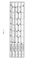
Fig. 5 is a diagram showing timings of throwing and exhausting waste; -
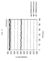
Fig. 6 is a diagram showing positions of locating a differential pressure gauge, thermocouples, and microwave sensors; -
Fig. 7 is a view showing variations of differential pressure between a gas blowing opening and an upper part of the fluidized layer; -
Figs. 8 to 10 are views showing temperature variations of thermocouples provided in the cylindrical-vertical type heating container; -
Fig. 11 is a view showing signal variations of microwave sensors provided in the cylindrical-vertical type heating container; -
Fig. 12 is an example for measuring the amount of total hydrocarbon contained in the exhaust gas by use of a FID; -
Fig. 13 is a view showing the relationship between the FID peak accumulated values and the amount of dioxins; and -
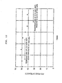
Fig. 14 is a view showing the relationship between the time required for volatilization and the amount of dioxins. -
Fig. 3 schematically shows an example of a waste treatment container of the invention. - Fly
ash 4 collected by a dust collector such as a bag filter of a garbage incinerating plant is thrown into a cylindrical-verticaltype heating container 5 from a throwing opening 6 thereof. - The thrown
fly ash 4 is stirred bygas 11 androtary wings 7 to form a fluidizedlayer 12, thegas 11 being heated up to 350 to 480 ºC and blown into the cylindrical-verticaltype heating container 5 from agas blowing opening 14 provided at the bottom thereof via awind box 10 and a dispersingplate 9, and therotary wings 7 being provided in the cylindrical-verticaltype heating container 5 and rotated at a speed of about 1 to 200 rpm. The fluidizedlayer 12 offly ash 4 is heated to 350 to 450 °C by the heatedgas 11 and an auxiliaryelectric heater 8 provided at an outer periphery of the cylindrical-verticaltype heating container 5. - In this case, since the
fly ash 4 is stirred and formed into the fluidizedlayer 12 by the blowinggas 11 and therotary wings 7, an exchange speed in the cylindrical-verticaltype heating container 5, for example, between a central part and a peripheral part thereof may be fast. Therefore, a very high heat transfer coefficient may be obtained and thefly ash 4 may be uniformly and efficiently heated. As a result, the harmful matter such as dioxins contained in thefly ash 4 may be volatilized and securely made harmless. Thefly ash 4 thus made harmless is exhausted via anexhausting opening 13 and is separated from the exhaust gas at adust remover 15. - If the waste is thrown into from the neighborhood of the surface of the fluidized layer already formed, it is possible to effectively prevent the lowering of gas temperature around the dust remover located above the upper part of the fluidized layer in the heater, and then to increase the volatilizing efficiency of the harmful matters such as dioxins. As a result, not only the removing efficiency of the harmful matters such as dioxins is increased, but also the energy required for the heating treatment and the blowing gas for promoting the volatilization of harmful matters may be decreased.
- For throwing the waste and exhausting the heat treated waste, if using pressure variations between the gas blowing opening and the upper part of fluidized layer, temperature variations in the cylindrical-vertical type heating container, or level variations measured by a level gauge such as a rotary type, a micro wave utilizing type, a sound wave utilizing type or an infrared ray utilizing type which is provided in the cylindrical-vertical type heating container, it is possible to correctly control the throwing and exhausting the amount of the waste. Further, thereby, the retention time or the amount of the waste in the heater can be correctly controlled. Accordingly, the heat treatment of the waste may be made more correctly, and a more excellent removing efficiency of harmful organic matters such as dioxins may be obtained.
- In case a time lag is provided between a time of throwing the waste and a time of discharging the heat treated waste, in comparison with a case of throwing the waste at a constant rate and consecutively, it is possible to suppress a phenomenon of short-cut that the thrown waste does not pass a fixed retention time and is exhausted in a time shorter than the fixed time. Thus, the retention time of the waste in the heater which is required to remove the harmful matters such as dioxins may be secured more correctly. Therefore, more excellent removing efficiency of harmful organic matters such as dioxins may be obtained.
- According to the method of the invention, for making harmless the volatilized harmful organic matters, a fluidized layer type catalyst or a moving layer type catalyst may be employed. In case of making harmless the harmful organic matters by using the catalyst, in comparison with a case that the harmful organic matters are not separated from the waste, a contacting efficiency between the harmful organic matters and the catalyst may be enhanced. Especially in the case of carrying out the treatment by means of the fluidized layer type catalyst or the moving layer type catalyst, in comparison with a case of carrying out the treatment with the fixed bed catalyst, the contacting efficiency with the catalyst may be enhanced. Namely, also in case a catalyst of fine particles is used, which may maintain the high contacting efficiency with the harmful organic matters contained in the exhaust gas, the increase of pressure loss due to choking by the dusts going into the catalyst layer together with the exhaust gas may be avoided by use of the fluidized layer type or the moving layer type. Therefore, the higher decomposition efficiency of the harmful matters such as dioxins may be obtained. Further, since the contacting efficiency is high, a required amount of the catalyst may be decreased, the waste may be treated harmless at a lower cost thereby.
- If treating the gas exhausted after the heat treatment with an organic matter oxidizing and decomposing catalyst containing a noble metal, in comparison with a case of using a catalyst having an oxide based catalytic activity ingredient, the harmful organic matters of dioxins may be completely oxidized and decomposed because of having a higher oxidation decomposing ability. Further, since a dioxin-associated matters causing formation of dioxin and other organic compounds may be effectively and completely oxidized and decomposed, the formation of dioxin in the exhaust gas after treatment may be prevented.
- According to the method of the invention, the high temperature burning decomposition method may be adapted to the treatment of making harmless the volatilized harmful organic matters. If using the burning decomposition method, in comparison with the case that the harmful organic matters are not volatilized from the waste, the amount of oxygen required for burning may be decreased. Therefore, also in a case of using air as an oxygen source, the treatment of making harmless may be performed without producing a large amount of the exhausted gas and NOx. Further, it is possible to employ a method of blowing gas containing harmful organic matters exhausted after the heat treatment into a high temperature part of an incinerator or a fusing furnace for decomposing them. In this method, if a waste treating apparatus of the invention is located in the neighborhood of an incinerator or a fusing facility which produces incinerator residue, the waste may be treated to be harmless at a lower cost without independently providing a heating device or the like required for burning decomposition.
- According to a method of the invention, if the amount of total hydrocarbon in the gas containing the volatilized harmful organic matters is measured before and/or after making harmless the harmful organic matter, the treating condition may be monitored on the basis of the measured results. If carrying out the treatments of volatilizing various organic compounds such as dioxin and other harmful organic matters from waste, moving them into exhausted gas, and making constant the amount of throwing waste into and exhausting from the heater, the temperatures in the heater, the amount of the blowing gas and so on, then the amount of total hydrocarbon in the exhaust gas is almost kept constant. On the other hand, in case any one of the treating conditions is off from the predetermined conditions, the amount of total hydrocarbon in the exhaust gas is varied. It is, therefore, possible to not only monitor the treating conditions on the basis of the measurement of the amount of total hydrocarbon in the exhaust gas, but also control at least one of the treating conditions. It is preferable that the measurement is continuously carried out.
- Further, if the amount of total hydrocarbon in the exhaust gas is continuously measured after the catalyst treatment, in case the exhaust gas is introduced under a proper treating condition, the organic matters are completely oxidized and decomposed, and the amount of total hydrocarbon at the catalyst outlet becomes almost 0. However, if the catalytic conditions such as the treating temperature or the amount of the exhaust gas are varied, the amount of total hydrocarbon is accordingly varied at the catalytic outlet. It is, therefore, possible to control at least one of the treating conditions in addition to monitoring the oxidation and decomposition condition of the organic matters by catalyst on the basis of the measured result. It is also preferable that the measurement is continuously carried out.
- In case a hydrogen frame ionization detector (FID) is provided in the apparatus of
Fig. 3 for analyzing the gas exhausted after the heat treatment, the treatment may be practiced while monitoring the amount of harmful matters of dioxins. It is possible to control the amount of throwing waste, the amount of blowing gas, the temperature of gas, the heating temperature and so on efficiently without waiting for analyzed results for which a long time has been taken in the prior art. - With the FID, by analyzing the total amount of total hydrocarbon volatilized from waste or the time to be taken until the volatilization of total hydrocarbon is completed, it is possible to quantify at least one sort of the harmful organic matters contained in the waste before or after heating treatment. It is, therefore, possible to detect the amount of harmful organic matters such as dioxins in a short time and to treat the waste while monitoring the detected results, and a harmless degree of waste under treating may be known at a real time.
- Further, with respect to a certain plurality of wastes, by means of the total volatilization amount of total hydrocarbon, otherwise the time to be taken until completion of volatilization of total hydrocarbon, and the amount of at least one sort of harmful organic matters, which have been sought by the above mentioned method, and by means of the total volatilization amount of total hydrocarbon of another waste unknown as to the content of the harmful organic matters, at least one sort of harmful organic matter contained in the another waste may be quantified. According to this method, the amount of harmful organic matters such as dioxins may be detected in a short time and with a higher precision than the quantifying method of the harmful organic matters by use of the FID and may treat the waste while monitoring the detected result. Thus the harmless degree of harmful matters may be known while the waste is treated.
- The fluidized layer may be also formed, besides by blowing gas and stirring the waste, by vibrating the cylindrical-vertical type heating container or by vibrating the waste by supersonic waves.
- For heating the fluidized layer of waste from the outside of the cylindrical-vertical type heating container, besides the heater, the retaining heat of incinerated exhaust gas from a garbage incinerating plant may be utilized. In order to more efficiently heat the fluidized layer of waste, a heater may be provided on the rotary wings or the rotating shaft.
- The rotary wings may be formed with stirring arms having rake-like wings, but in case of the waste of low fluidity, fixing bars may be provided between the rotary wings to prevent the decrease of stirring efficiency.
-
Fig. 4 shows a process flow of a waste treatment method of the invention. - Fly ash is continuously transported from a fly
ash storing vessel 22 by aconveyer 23, and thrown into a cylindrical-verticaltype heating container 24. The fly ash is, after the heat treatment, added with aheavy metal stabilizer 26 at afly ash mixer 25 where a treatment is practiced to prevent the heavy metal from eluting. The gas coming out of the heater is, after removing dusts at abag filter 27, introduced into acatalyst reactor 28 where the organic matters containing dioxins are oxidized and decomposed. Here,reference numeral 20 denotes an air blowing fan, 21 denotes a heater for heating a blown air, and 29 denotes an air attracting blower. - Table 1 shows the test conditions. Table 2 shows the catalytic conditions with platinum being used as a noble metal catalyst and with cordierite used as a carrier of catalyst. The analysis of dioxins was carried out at the
positions ① to ⑥ as shown inFig. 4 . - Table 3 shows the analyzed results of dioxins in the fly ash.
- At the outlet of the heater, the amount of dioxins is reduced to 0.0044 ng-TEQ/g. Further, although there was no rapid cooling process after the outlet of the heater, the formation of dioxins was scarcely seen on the way to the outlet of the fly ash stabilizing treatment process.
- Table 4 shows the analyzed results of dioxins in the exhaust gas.
- Although a large amount of dioxins of 100.9 ng-TEQ/m3N was contained in the gas at the outlet of the bag filter, the amount is reduced to 0.0321 ng-TEQ/m3N at the outlet of the catalyst reactor.
Table 1 Item Unit Set values Amount of treating fly ash Kg/ h 60 Amount of blowing air m3N/ h 20 Temperature of heater ° C 450 Temperature of fluidized layer °C 420 Temperature of catalyst °C 400 Table 2 Item Set values Number of catalyst 80 Carrier of catalyst Cordierite Amount of catalyst [m3] 0.01 Space velocity [h-1] 2000 Table 3 Analyzing positions Dioxins ng-TEQ/ g ① Store outlet 0.609 ② Heater outlet 0.0044 ③ After stabilization . 0.0154 Table 4 Analyzing positions Amount of dioxins ng-TEQ/ g ④ Bag filter 100.9 ④ Catalyst outlet 0.0321 - While the fly ash was heated to 420ºC, the dioxin removing rate was searched using the waste treatment apparatus shown in
Fig. 3 , where the fly ash containing dioxin was thrown into from the top of cylindrical-vertical type heating container, and from the neighborhood of the surface of fluidized layer. - Table 5 shows the dioxin removing rates.
- It is seen that the dioxin removing rate is higher in case the waste is thrown into from the neighborhood of the surface of fluidized layer.
Table 5 Throwing position of fly ash Temperature of fly ash (°C) Temperature around dust remover (°C) Removing rate of DXN (%) Top of heating container 420 395 87 Near surface of fluidized layer 420 418 99.5 - The dioxin removing rate was searched under the conditions of Table 1 through the process of the example 1 by changing timings of throwing and exhausting the waste under the conditions I to IV as shown in
Fig. 5 .Fig. 6 shows the positions of newly provided adifferential pressure gauge 40, a thermocouple A41, another thermocouple B42, a further thermocouple C43, asignal generating part 44 and asignal receiving part 45 of the microwave sensor. - As a result, obtained were variations of the differential pressure shown in
Fig. 7 , temperature variations of thermocouples shown inFigs. 8 to 10 , and signal variations of the microwave sensor shown inFig. 11 . According to these results, since the level of fluidized layer sensitively react on these three parameters, it is seen that these parameters may be used for controlling the level of fluidized layer. - Table 6 shows the dioxin removing rates.
- It is seen that the highest dioxin removing rate is obtained under the condition IV of a batch treatment where the waste is not simultaneously thrown into and exhausted out, and the lowest dioxin removing rate is obtained under the condition I where the waste is always continuously thrown into and exhausted out. Under the conditions II and III where a time lag is provided in throwing and exhausting, the dioxin removing rates are intermediate between the conditions I and IV. As to the conditions II and III, a higher dioxin removing rate is obtained in the case of condition III where the waste is never simultaneously thrown into and exhausted out.
Table 6 Conditions I II III IV Removing rate of DXN (%) 95 97 99 99.9 - The amount of total hydrocarbon was measured by use of the FID in the process of the example 1 and under the same conditions as those of Table 1 except the temperature of the fluidized layer, while the incinerated fly ash is treated. The temperatures of the fluidized layer were 300°C in one case and 400°C in another case.
-
Fig. 12 shows the amount of total hydrocarbon contained in the exhaust gas by use of the FID. - When the FID peak intensity is about 50, the temperature of the fly ash in the volatilizing vessel is 400 °C and the removing rate of dioxins is 98%.
- On the other hand, when the FID peak intensity is about 40, the temperature of the fly ash in the volatilizing vessel is 350°C and the removing rate of dioxins is 65 %.
- Thus, since the FID peak intensity is closely related to the temperature of the fly ash in the volatilizing vessel and to the removing rate of dioxins, a high removing rate of dioxins may be maintained by controlling the temperature of fly ash on the basis of analyzed results of the exhaust gas by use of the FID.
- If the measurement is continuously carried out, a response may be quickly taken to a change in removing rate of harmful organic matters in the waste, thereby the waste may be treated always under the optimum conditions.
- With preparation of a plurality of sorts of fly ashes, the amount of dioxins was measured as to each ash by making in order a pretreatment with use of acid, an extraction treatment with use of organic solvent, a concentration treatment and an analysis with use of GC-MS. On the other hand, with preparation of the same sorts of fly ashes, and with volatilization of the organic compounds by heating 2.0 g of respective ash up to 400°C while an air is circulated at a constant amount, the gas containing the volatilized organic compounds was analyzed.
- The data obtained by the FID is given as a change of voltage relative to a time, and the voltage corresponds to the amount or the volatilization amount of volatilized organic compounds. Namely, the accumulated value (FID peak accumulated value) obtained by a time integration of the voltage obtained by the FID corresponds to the total volatilization amount of organic compounds, and the time from the beginning of volatilization to the time when the voltage becomes zero corresponds to a time taken until the volatilization of the organic compounds has been completed.
- Therefore, as to these fly ashes, the relation between the FID peak accumulated value and the amount of dioxins and the relation between the volatilization required time and the amount of dioxins were sought.
- The results are shown in
Figs. 13 and 14 . - It may be seen that the FID peak accumulated value or the amount of dioxins and the volatilization required time are clearly related to each other.
- Next, with preparation of an ash which is unknown as to the amount of dioxins, the FID peak accumulated value and the volatilization required time were sought also under the same conditions as described above.
- As a result, the FID peak accumulated value was 200 and the volatilization required time was 45 minutes. Referring the values to
Figs. 13 and 14 , it could be estimated that in both cases the amount of dioxins in the fly ash was 0.025 ng-TEQ/g. - Further, for confirming the results, the amount of dioxins was measured as to the same sort of the fly ash by making in order the pretreatment with use of acid, the extraction treatment with use of organic solvent, the concentration treatment and an analysis with use of GC-MS.
- As a result, it was found that the amount of dioxins in the fly ash was 0.03 ng-TEQ/g. From this result, it was confirmed that by combining the volatilization treatment and the measurement by use of the FID, dioxins could be precisely quantified.
- It is possible to quantify the other harmful organic matters including PCN by preparing in advance graphs such as those as shown in
Figs. 13 and 14 . Similarly, it is possible to quantify all of the harmful organic matters such as dioxins and PCN.
Claims (4)
- A treatment method of fly ash (4) containing harmful organic matters, the method comprising the steps of:throwing the fly ash (4) into a cylindrical-vertical type heating container (5);forming a fluidized layer (12) of the fly ash (4) by blowing heated gas (11) into the cylindrical-vertical heating container (5) from a gas blowing opening (14) provided at the bottom of the container (5), and by agitating the thrown fly ash (4) by an agitator that provides a plurality of rotary wings (7) inside the container (5);heating the fluidized layer up to 350°C to 450°C with the heated gas (11) and a heater (8) provided around an outer periphery of the container (5);separating and exhausting the heated fly ash (4) and gas (11); andvolatilizing the harmful organic matters contained in the fly ash (4).
- The treatment method as defined in claim 1, wherein blowing of the heated gas (11) is carried out by blowing the heated gas (11) via a dispersing plate (9) which is located at the bottom part of the container (5).
- The treatment method as defined in claim 1, wherein throwing of the fly ash (4) is carried out from the neighborhood of the surface of the fluidized layer (12) which has been already formed.
- A treatment apparatus for performing a method according to any of claims 1 to 3, the apparatus comprising:a cylindrical-vertical type heating container (5) into which the fly ash (4) is thrown;a heater (8) provided around an outer periphery of the container (5);an agitator that provides a plurality of rotary wings (7) inside the container (5);a heated gas (11) blowing opening (14) provided at the bottom of the container (5);an exhausting opening (13) for exhausting the heat treated fly ash (4);a dust remover (15) for separating the heat treated fly ash (4) from the gas (11) to be exhausted after heat-treating, anda noble metal catalyst reactor (28) for oxidizing and decomposing the harmful organic matters in the exhausted gas.
Applications Claiming Priority (7)
| Application Number | Priority Date | Filing Date | Title |
|---|---|---|---|
| JP2000052144 | 2000-02-23 | ||
| JP2000052144 | 2000-02-23 | ||
| JP2000137212 | 2000-05-10 | ||
| JP2000137212A JP3716706B2 (en) | 2000-05-10 | 2000-05-10 | Waste analysis method |
| JP2000352179 | 2000-11-20 | ||
| JP2000352179 | 2000-11-20 | ||
| PCT/JP2001/001234 WO2001062403A1 (en) | 2000-02-23 | 2001-02-21 | Method and device for processing waste |
Publications (3)
| Publication Number | Publication Date |
|---|---|
| EP1197270A1 EP1197270A1 (en) | 2002-04-17 |
| EP1197270A4 EP1197270A4 (en) | 2003-10-15 |
| EP1197270B1 true EP1197270B1 (en) | 2010-06-02 |
Family
ID=27342500
Family Applications (1)
| Application Number | Title | Priority Date | Filing Date |
|---|---|---|---|
| EP01906153A Expired - Lifetime EP1197270B1 (en) | 2000-02-23 | 2001-02-21 | Method and device for processing waste |
Country Status (5)
| Country | Link |
|---|---|
| EP (1) | EP1197270B1 (en) |
| KR (1) | KR20010105393A (en) |
| DE (1) | DE60142278D1 (en) |
| TW (1) | TW499331B (en) |
| WO (1) | WO2001062403A1 (en) |
Families Citing this family (4)
| Publication number | Priority date | Publication date | Assignee | Title |
|---|---|---|---|---|
| JP3465708B1 (en) * | 2002-06-26 | 2003-11-10 | Jfeエンジニアリング株式会社 | Heat treatment equipment for powdery waste |
| CN106734102A (en) * | 2016-12-30 | 2017-05-31 | 天津梦之岛科技有限公司 | A kind of waste treatment equipment |
| CN109539268B (en) * | 2018-10-19 | 2020-06-16 | 滁州米润科技有限公司 | Prevent secondary pollution's case and bag production waste material processing apparatus |
| CN109675921B (en) * | 2019-01-11 | 2023-09-05 | 浙江亿可利环保科技有限公司 | Continuous organic contaminated soil direct thermal desorption system and thermal desorption method thereof |
Family Cites Families (14)
| Publication number | Priority date | Publication date | Assignee | Title |
|---|---|---|---|---|
| US3509835A (en) | 1968-03-04 | 1970-05-05 | Gen Electric | Combined filter-incinerator device for waste disposal system |
| JPS5145475A (en) | 1974-10-15 | 1976-04-17 | Kogyo Gijutsuin | Toshigomino ekikashorihoho |
| JPS5824710A (en) * | 1981-08-05 | 1983-02-14 | Kawasaki Heavy Ind Ltd | Height control of static bed of fluidized medium in boiler of fluidized-bed combustion type |
| JPS5948431U (en) * | 1982-09-21 | 1984-03-30 | バブコツク日立株式会社 | Fluidized bed furnace pressure control device |
| US5276250A (en) * | 1986-07-11 | 1994-01-04 | Hagenmaier Hans Paul | Process for decomposing polyhalogenated compounds |
| DE3644381A1 (en) * | 1986-12-24 | 1988-07-07 | Berlin Consult Gmbh | METHOD AND SYSTEM FOR MINIMIZING POLLUTANT EMISSIONS FROM COMBUSTION PLANTS |
| DE3721476C1 (en) * | 1987-06-30 | 1988-12-22 | Asea Brown Boveri | Process for regulating the fluidized bed height in a pyrolysis reactor and arrangement for carrying out the process |
| DE3934447C2 (en) * | 1989-02-16 | 1999-02-11 | Saarbergwerke Ag | Process and plant for degassing solid fuel in a fluidized bed reactor |
| JPH04110768A (en) * | 1990-08-31 | 1992-04-13 | Shimadzu Corp | Hydrocarbon analysis method and analysis device |
| JP2749492B2 (en) * | 1992-12-07 | 1998-05-13 | 日立造船株式会社 | Incinerator loading device for fluidized bed incinerator |
| DE4303722C1 (en) * | 1993-02-10 | 1994-05-05 | Metallgesellschaft Ag | Decontamination of soil, sand, sludge or solid aggregate or residue - by heating with recycled hot gas or super-heated steam contg. oxidant, removing dust, condensing impurities and chemical or physical removal |
| JP3103719B2 (en) | 1994-06-06 | 2000-10-30 | 三造環境エンジニアリング株式会社 | Apparatus and method for heat dechlorination of dust ash |
| JP3366246B2 (en) * | 1998-03-06 | 2003-01-14 | 日本鋼管株式会社 | Method and apparatus for treating incinerated fly ash |
| EP1048366B1 (en) * | 1999-04-27 | 2005-10-12 | JFE Engineering Corporation | A method for disposing a waste |
-
2001
- 2001-02-21 KR KR1020017012243A patent/KR20010105393A/en not_active Ceased
- 2001-02-21 EP EP01906153A patent/EP1197270B1/en not_active Expired - Lifetime
- 2001-02-21 DE DE60142278T patent/DE60142278D1/en not_active Expired - Lifetime
- 2001-02-21 WO PCT/JP2001/001234 patent/WO2001062403A1/en not_active Ceased
- 2001-02-23 TW TW090104151A patent/TW499331B/en not_active IP Right Cessation
Also Published As
| Publication number | Publication date |
|---|---|
| EP1197270A4 (en) | 2003-10-15 |
| DE60142278D1 (en) | 2010-07-15 |
| KR20010105393A (en) | 2001-11-28 |
| EP1197270A1 (en) | 2002-04-17 |
| WO2001062403A1 (en) | 2001-08-30 |
| TW499331B (en) | 2002-08-21 |
Similar Documents
| Publication | Publication Date | Title |
|---|---|---|
| CZ117994A3 (en) | Process and apparatus for removing volatile and semi-volatile contaminants from contaminated materials | |
| CN108372197A (en) | A kind of combination process based on thermal desorption for pollution administration soil | |
| CN113894150A (en) | Energy-saving efficient thermal desorption remediation method for organic contaminated soil | |
| EP1197270A1 (en) | Method and device for processing waste | |
| JP3103719B2 (en) | Apparatus and method for heat dechlorination of dust ash | |
| JP2002282817A (en) | Apparatus for treating waste and method for detoxifying harmful substances or objects containing the same | |
| JP3465708B1 (en) | Heat treatment equipment for powdery waste | |
| JP3479626B2 (en) | Multi-tube external heat kiln | |
| JP3510300B2 (en) | Waste treatment equipment | |
| JP4494432B2 (en) | Equipment for treating harmful substances such as organic halogen compounds | |
| JP2001276817A (en) | Contaminated soil discharge water treatment equipment | |
| JP2001025735A (en) | Ash treatment method | |
| JP3449356B2 (en) | Powdery waste heat treatment equipment | |
| JP3465691B2 (en) | Heat treatment method and apparatus for powdery waste | |
| JP4084742B2 (en) | Organohalogen compound processing equipment | |
| JP3727908B2 (en) | Soil treatment method | |
| JP3465692B2 (en) | Powdery waste heat treatment equipment | |
| JP2002355638A (en) | Ash heat treatment method | |
| JP3465709B1 (en) | Heat treatment apparatus for powdery waste and method of operating the same | |
| JP4160065B2 (en) | Soil treatment equipment | |
| CN112762459B (en) | Device and method for eliminating dioxin in fly ash | |
| JPH07138054A (en) | Method for treating dioxin-containing dust treating device therefor | |
| JP5144864B2 (en) | Purification equipment for contaminated soil | |
| JP2001259578A (en) | Garbage disposal equipment | |
| JP2003083527A (en) | Method and apparatus for purifying contaminated soil |
Legal Events
| Date | Code | Title | Description |
|---|---|---|---|
| PUAI | Public reference made under article 153(3) epc to a published international application that has entered the european phase |
Free format text: ORIGINAL CODE: 0009012 |
|
| 17P | Request for examination filed |
Effective date: 20011030 |
|
| AK | Designated contracting states |
Kind code of ref document: A1 Designated state(s): AT BE CH CY DE DK ES FI FR GB GR IE IT LI LU MC NL PT SE TR |
|
| AX | Request for extension of the european patent |
Free format text: AL;LT;LV;MK;RO;SI |
|
| RIC1 | Information provided on ipc code assigned before grant |
Ipc: 7F 23G 5/14 B Ipc: 7G 01N 27/04 B Ipc: 7B 09B 3/00 A Ipc: 7B 09C 1/06 B Ipc: 7F 23G 5/027 B Ipc: 7F 23G 7/14 B Ipc: 7F 23G 7/06 B Ipc: 7F 23C 10/22 B Ipc: 7B 01D 53/86 B Ipc: 7F 23G 5/30 B |
|
| A4 | Supplementary search report drawn up and despatched |
Effective date: 20030827 |
|
| RAP1 | Party data changed (applicant data changed or rights of an application transferred) |
Owner name: JFEENGINEERING CORPORATION |
|
| RBV | Designated contracting states (corrected) |
Designated state(s): DE GB |
|
| 17Q | First examination report despatched |
Effective date: 20040602 |
|
| GRAP | Despatch of communication of intention to grant a patent |
Free format text: ORIGINAL CODE: EPIDOSNIGR1 |
|
| GRAS | Grant fee paid |
Free format text: ORIGINAL CODE: EPIDOSNIGR3 |
|
| GRAA | (expected) grant |
Free format text: ORIGINAL CODE: 0009210 |
|
| AK | Designated contracting states |
Kind code of ref document: B1 Designated state(s): DE GB |
|
| REG | Reference to a national code |
Ref country code: GB Ref legal event code: FG4D |
|
| REF | Corresponds to: |
Ref document number: 60142278 Country of ref document: DE Date of ref document: 20100715 Kind code of ref document: P |
|
| PLBE | No opposition filed within time limit |
Free format text: ORIGINAL CODE: 0009261 |
|
| STAA | Information on the status of an ep patent application or granted ep patent |
Free format text: STATUS: NO OPPOSITION FILED WITHIN TIME LIMIT |
|
| 26N | No opposition filed |
Effective date: 20110303 |
|
| REG | Reference to a national code |
Ref country code: DE Ref legal event code: R097 Ref document number: 60142278 Country of ref document: DE Effective date: 20110302 |
|
| PGFP | Annual fee paid to national office [announced via postgrant information from national office to epo] |
Ref country code: DE Payment date: 20150218 Year of fee payment: 15 |
|
| PGFP | Annual fee paid to national office [announced via postgrant information from national office to epo] |
Ref country code: GB Payment date: 20150218 Year of fee payment: 15 |
|
| REG | Reference to a national code |
Ref country code: DE Ref legal event code: R119 Ref document number: 60142278 Country of ref document: DE |
|
| GBPC | Gb: european patent ceased through non-payment of renewal fee |
Effective date: 20160221 |
|
| PG25 | Lapsed in a contracting state [announced via postgrant information from national office to epo] |
Ref country code: GB Free format text: LAPSE BECAUSE OF NON-PAYMENT OF DUE FEES Effective date: 20160221 Ref country code: DE Free format text: LAPSE BECAUSE OF NON-PAYMENT OF DUE FEES Effective date: 20160901 |