EP1197267A1 - Viscous material applicator - Google Patents
Viscous material applicator Download PDFInfo
- Publication number
- EP1197267A1 EP1197267A1 EP00908039A EP00908039A EP1197267A1 EP 1197267 A1 EP1197267 A1 EP 1197267A1 EP 00908039 A EP00908039 A EP 00908039A EP 00908039 A EP00908039 A EP 00908039A EP 1197267 A1 EP1197267 A1 EP 1197267A1
- Authority
- EP
- European Patent Office
- Prior art keywords
- viscous material
- chamber
- pressure
- pressurized chamber
- application
- Prior art date
- Legal status (The legal status is an assumption and is not a legal conclusion. Google has not performed a legal analysis and makes no representation as to the accuracy of the status listed.)
- Withdrawn
Links
Images













Classifications
-
- H—ELECTRICITY
- H05—ELECTRIC TECHNIQUES NOT OTHERWISE PROVIDED FOR
- H05K—PRINTED CIRCUITS; CASINGS OR CONSTRUCTIONAL DETAILS OF ELECTRIC APPARATUS; MANUFACTURE OF ASSEMBLAGES OF ELECTRICAL COMPONENTS
- H05K3/00—Apparatus or processes for manufacturing printed circuits
- H05K3/10—Apparatus or processes for manufacturing printed circuits in which conductive material is applied to the insulating support in such a manner as to form the desired conductive pattern
-
- B—PERFORMING OPERATIONS; TRANSPORTING
- B05—SPRAYING OR ATOMISING IN GENERAL; APPLYING FLUENT MATERIALS TO SURFACES, IN GENERAL
- B05C—APPARATUS FOR APPLYING FLUENT MATERIALS TO SURFACES, IN GENERAL
- B05C11/00—Component parts, details or accessories not specifically provided for in groups B05C1/00 - B05C9/00
- B05C11/10—Storage, supply or control of liquid or other fluent material; Recovery of excess liquid or other fluent material
- B05C11/1047—Apparatus or installations for supplying liquid or other fluent material comprising a buffer container or an accumulator between the supply source and the applicator
-
- B—PERFORMING OPERATIONS; TRANSPORTING
- B05—SPRAYING OR ATOMISING IN GENERAL; APPLYING FLUENT MATERIALS TO SURFACES, IN GENERAL
- B05C—APPARATUS FOR APPLYING FLUENT MATERIALS TO SURFACES, IN GENERAL
- B05C11/00—Component parts, details or accessories not specifically provided for in groups B05C1/00 - B05C9/00
-
- B—PERFORMING OPERATIONS; TRANSPORTING
- B05—SPRAYING OR ATOMISING IN GENERAL; APPLYING FLUENT MATERIALS TO SURFACES, IN GENERAL
- B05C—APPARATUS FOR APPLYING FLUENT MATERIALS TO SURFACES, IN GENERAL
- B05C5/00—Apparatus in which liquid or other fluent material is projected, poured or allowed to flow on to the surface of the work
- B05C5/02—Apparatus in which liquid or other fluent material is projected, poured or allowed to flow on to the surface of the work the liquid or other fluent material being discharged through an outlet orifice by pressure, e.g. from an outlet device in contact or almost in contact, with the work
-
- B—PERFORMING OPERATIONS; TRANSPORTING
- B41—PRINTING; LINING MACHINES; TYPEWRITERS; STAMPS
- B41F—PRINTING MACHINES OR PRESSES
- B41F15/00—Screen printers
- B41F15/14—Details
- B41F15/40—Inking units
- B41F15/42—Inking units comprising squeegees or doctors
-
- H—ELECTRICITY
- H05—ELECTRIC TECHNIQUES NOT OTHERWISE PROVIDED FOR
- H05K—PRINTED CIRCUITS; CASINGS OR CONSTRUCTIONAL DETAILS OF ELECTRIC APPARATUS; MANUFACTURE OF ASSEMBLAGES OF ELECTRICAL COMPONENTS
- H05K3/00—Apparatus or processes for manufacturing printed circuits
- H05K3/10—Apparatus or processes for manufacturing printed circuits in which conductive material is applied to the insulating support in such a manner as to form the desired conductive pattern
- H05K3/12—Apparatus or processes for manufacturing printed circuits in which conductive material is applied to the insulating support in such a manner as to form the desired conductive pattern using thick film techniques, e.g. printing techniques to apply the conductive material or similar techniques for applying conductive paste or ink patterns
- H05K3/1216—Apparatus or processes for manufacturing printed circuits in which conductive material is applied to the insulating support in such a manner as to form the desired conductive pattern using thick film techniques, e.g. printing techniques to apply the conductive material or similar techniques for applying conductive paste or ink patterns by screen printing or stencil printing
- H05K3/1233—Methods or means for supplying the conductive material and for forcing it through the screen or stencil
-
- H—ELECTRICITY
- H05—ELECTRIC TECHNIQUES NOT OTHERWISE PROVIDED FOR
- H05K—PRINTED CIRCUITS; CASINGS OR CONSTRUCTIONAL DETAILS OF ELECTRIC APPARATUS; MANUFACTURE OF ASSEMBLAGES OF ELECTRICAL COMPONENTS
- H05K3/00—Apparatus or processes for manufacturing printed circuits
- H05K3/30—Assembling printed circuits with electric components, e.g. with resistors
- H05K3/32—Assembling printed circuits with electric components, e.g. with resistors electrically connecting electric components or wires to printed circuits
- H05K3/34—Assembling printed circuits with electric components, e.g. with resistors electrically connecting electric components or wires to printed circuits by soldering
-
- B—PERFORMING OPERATIONS; TRANSPORTING
- B05—SPRAYING OR ATOMISING IN GENERAL; APPLYING FLUENT MATERIALS TO SURFACES, IN GENERAL
- B05C—APPARATUS FOR APPLYING FLUENT MATERIALS TO SURFACES, IN GENERAL
- B05C5/00—Apparatus in which liquid or other fluent material is projected, poured or allowed to flow on to the surface of the work
- B05C5/02—Apparatus in which liquid or other fluent material is projected, poured or allowed to flow on to the surface of the work the liquid or other fluent material being discharged through an outlet orifice by pressure, e.g. from an outlet device in contact or almost in contact, with the work
- B05C5/0254—Coating heads with slot-shaped outlet
-
- H—ELECTRICITY
- H05—ELECTRIC TECHNIQUES NOT OTHERWISE PROVIDED FOR
- H05K—PRINTED CIRCUITS; CASINGS OR CONSTRUCTIONAL DETAILS OF ELECTRIC APPARATUS; MANUFACTURE OF ASSEMBLAGES OF ELECTRICAL COMPONENTS
- H05K2203/00—Indexing scheme relating to apparatus or processes for manufacturing printed circuits covered by H05K3/00
- H05K2203/01—Tools for processing; Objects used during processing
- H05K2203/0104—Tools for processing; Objects used during processing for patterning or coating
- H05K2203/0126—Dispenser, e.g. for solder paste, for supplying conductive paste for screen printing or for filling holes
Definitions
- the present invention relates to a viscous material application apparatus for applying a viscous material such as an adhesive, cream solder or a conductive paste to an application target such as a circuit board.
- this viscous material application apparatus comprises a material supply section 1 for holding a viscous material 5 such as an adhesive or cream solder, and a pressure regulating section 22 for regulating and supplying compressed air to the material supply section 1, and the viscous material 5 is pressurized by the compressed air, and discharged from a discharge port 4a of a discharge section 4.
- a viscous material 5 such as an adhesive or cream solder
- a pressure regulating section 22 for regulating and supplying compressed air to the material supply section 1
- the viscous material 5 is pressurized by the compressed air, and discharged from a discharge port 4a of a discharge section 4.
- a valve 16 for starting and stopping the supply of compressed air may also be provided between the material supply section 1 and the discharge section 4.
- the viscous material 5 is pressurized from above by compressed air supplied from the pressure regulating section 22 and forced downward, and the valve 16 is then opened and the viscous material 5 discharged from the discharge port 4a. Then, when application onto the circuit board has been completed, the valve 16 is closed.
- the response time from the point where a signal is output to start discharge at a predetermined pressure, to the point where discharge at that pressure is actually started also lengthens for the same reasons, and so a waiting period develops from transmission of a discharge start signal to the actual start of discharge.
- a waiting period develops from transmission of a discharge start signal to the actual start of discharge.
- residual pressure remains, and so other problems arise such as the viscous material 5 hanging down from the discharge port 4a being forced out near the discharge port 4a and adhering to the circuit board, creating a bridge, when the viscous material application apparatus is next positioned on the circuit board.
- the present invention aims to resolve the above problems, with an object of providing a viscous material application apparatus capable of improving discharge accuracy and increasing efficiency by carrying out the pressure transmission for discharging the viscous material efficiently, and improving the responsiveness.
- a viscous material application apparatus of the present invention comprises: a main body having a pressurized chamber which connects through to a discharge port and stores a viscous material; and a viscous material supply device for transferring the viscous material under pressure to the pressurized chamber, wherein a discharge pressure regulating device for regulating the discharge pressure of the viscous material by increasing or decreasing the capacity of the pressurized chamber when the viscous material inside the pressurized chamber is pressurized and discharged is provided either inside the pressurized chamber or facing the pressurized chamber.
- the viscous material stored in the pressurized chamber is discharged with a discharge pressure regulated by the discharge pressure regulating device provided either inside the pressurized chamber or facing the pressurized chamber, the air pressure is transmitted efficiently and uniformly to the viscous material, and so the responsiveness from the start of pressurization to the start of discharge improves, and a suitable discharge quantity of the viscous material is discharged almost instantaneously. Then, following completion of the discharge, because no residual pressure remains within the pressurized chamber, the problem seen in conventional apparatus, where the viscous material hangs down from the discharge port and then adheres to the application target during the next application, is prevented.
- the discharge pressure regulating device may suitably comprise a pouch positioned inside the pressurized chamber for increasing or decreasing internal capacity thereof through the intake or exhausting of gas, and an air supply section for regulating the pressure inside the pouch by either supplying gas to, or discharging gas from the pouch, and as the shape of the pouch transforms with the intake or exhausting of gas from the air supply section and the pressurized chamber, the capacity of the pressurized chamber is increased or decreased, enabling the discharge pressure to be easily adjusted.
- the closer the air pouch is positioned to the discharge port inside the pressurized chamber the smaller the difference will be between the air pressure used for discharge and the actual discharge pressure, and the more the responsiveness is improved.
- the discharge pressure regulating device may also be constructed from an actuator such as an air cylinder and a voice coil motor, and a diaphragm which transforms under the influence of the actuator and increases or decreases the capacity inside the pressurized chamber.
- an actuator such as an air cylinder and a voice coil motor
- a diaphragm which transforms under the influence of the actuator and increases or decreases the capacity inside the pressurized chamber.
- Another suitable configuration uses a plurality of discharge pressure regulating devices, with the discharge pressure of the viscous material at a discharge position being regulated as desired, and this configuration enables localized pressure regulation to be performed with ease.
- these inclined plates function as a substitute for a squeegee in the aforementioned screen printing, and enable the filling of a screen opening with printing paste to be appropriately performed by discharge pressure regulation, and so highly accurate printing is possible, and an improvement in printing quality is achieved.
- the viscous material supply device used for transferring the viscous material under pressure in the aforementioned configuration, by forming the main body to allow for easy exchange, and enabling a cartridge filled with a viscous material to be accommodated within the main body, the viscous material is stored in the pressurized chamber, the pressurizing device for supplying the viscous material becomes unnecessary, and supply of the viscous material is simplified.
- a soft elastic material is inserted between the aforementioned inclined plates and the lower side surfaces of the pressurized chamber.
- the inclined plates when the inclined plates are pressed onto the screen, the inclined plates flex causing an improvement in the adhesion with the screen. Accordingly, the problem of the viscous material seeping out between the inclined plates and the screen when the viscous material is supplied into the pressurized chamber or when the viscous material inside the pressurized chamber is pressurized is prevented.
- the inclined plates need to be lengthened to increase their flexion.
- Such lengthening causes the capacity of the pressurized chamber to increase and the amount of supplied viscous material to increase, which leads to an increase in the supply time and an increase in the weight of the application unit.
- a soft elastic material between the inclined plates and the lower side surfaces of the pressurized chamber, the capacity of the pressurized chamber is kept small while still ensuring flexion of the inclined plates, and the volume of the viscous material is kept to a minimum.
- the soft elastic material could also be constructed along the inclined plates, and may be connected at the edges of the two plates, or alternatively separate pieces of soft elastic material are also inserted at the edges of the inclined plates. When large amounts of viscous material are permissible, the soft elastic material need not be formed along the inclined plates, and a soft material could be inserted only at the tips of the inclined plates.
- a pouch which functions as a discharge pressure regulating device absorbs this residual supply pressure remaining in the pressurized chamber, causing a reduction in the pressure inside the pressurized chamber. Accordingly, the residual pressure within the pressurized chamber is removed, and the discharge pressure is controlled using the aforementioned pouch.
- the pressure detecting member detects when the pressurized chamber is full of the viscous material.
- the viscous material supply device is used to supply the viscous material to replenish the viscous material within the pressurized chamber.
- the pressurized chamber is moved while pressurized by the discharge pressure regulating device, and the pressure of the discharge pressure regulating device is regulated based on a pressure of the pressurized chamber detected with the pressure detecting member.
- a rotatable shaft is provided in the pressurized chamber, and the viscous material is mobilized by rotating the shaft.
- the viscous material is recovered into the pressurized chamber by setting the pressure of the pressurized chamber to a negative pressure by the discharge pressure regulating device following completion of discharge, and lifting the pressurized chamber while moving the chamber in a horizontal direction.
- the temperature of the viscous material is stabilized by exchanging the air inside an air pouch.
- a viscous material application apparatus comprises a material supply section 1, an air supply section 2, and an application unit 3 which forms a main body of the apparatus.
- the material supply section 1 contains a viscous material 5 such as an adhesive and cream solder stored inside a cylinder shaped storage tank 1b, and under the effect of compressed air used for material supply, a plunger 1a operates and pressurizes the viscous material 5, and transfers the viscous material under pressure so that the inside of a chamber (pressurized chamber) 3c of the application unit 3 is always full.
- a viscous material 5 such as an adhesive and cream solder stored inside a cylinder shaped storage tank 1b
- the application unit 3 and the material supply section 1 are connected by a joint 6, and by positioning a through aperture 6a provided in the joint 6 so that the through aperture 6a interconnects with a viscous material supply passage 3d provided horizontally in the side of the aforementioned chamber 3c, the viscous material 5 is supplied to the inside of the application unit 3.
- a discharge nozzle 4b extends from a discharge section 4 at the bottom of the application unit 3.
- the air supply section 2 is positioned at the top of the application unit 3, and compressed air from this air supply section 2, which has been adjusted to a predetermined pressure for use in material supply, is transferred into an air pouch 3b occupying the entire upper portion of the inside of the chamber 3c.
- this air pouch 3b and the aforementioned air supply section 2 make up the discharge pressure regulating device.
- compressed air was used in this embodiment, an inert gas such as nitrogen gas could also be used as the gas phase.
- the air pouch 3b is formed from a pouch shaped vessel made of rubber or a resin material such as a urethane elastomer, polyethylene or nylon or the like, with a thickness of 0.03mm to 1mm for example. Furthermore, on consideration of the composition of the viscous material 5, the use of a solvent resistant material for the air pouch is also desirable. Preferred thickness for the air pouch is in the range of 0.3mm to 0.5mm. If the thickness of the air pouch 3b is overly thin, then there is a danger of the pouch rupturing.
- the air pouch 3b needs to be pressurized when the viscous material 5 is supplied into the chamber 3c, in order to absorb residual supply pressure remaining in the chamber 3c, and there is a possibility of the air pouch 3b rupturing at this time. Furthermore, if the thickness of the air pouch 3b is overly thick then there is a danger of deterioration in the responsiveness of the expansion and contraction of the pouch.
- the capacity of the chamber 3c inside the application unit 3 either decreases or increases. Accordingly, the viscous material 5 inside the chamber 3c is pushed out or sucked up under a predetermined pressure. Furthermore, by shortening the distance from the air pouch 3b to the discharge port 4a to approximately 10mm for example, the responsiveness is improved.
- the efficiency of pressure transmission is improved by a discharge pressure regulating function which utilizes the expansion and contraction action of the air pouch 3b associated with the supply and exhaust actions of the air supply section 2, and the effects on the flow characteristics of the viscous material 5 stored in the chamber 3c are reduced.
- the exhaust action of the air supply section 2 is realized by either releasing the air inside the air pouch 3b into the atmosphere, or by suctioning the air out.
- an air cylinder 7 which is connected to the air supply section 2 and a diaphragm 7b which is described below are used instead of the aforementioned discharge pressure regulating air pouch 3b.
- a piston 7a is provided in the air cylinder 7, and compressed air from the air supply section 2 which has been adjusted to a predetermined air pressure is supplied from an air port 3a, and accordingly the piston 7a moves up and down causing a deformation of the diaphragm 7b attached to the bottom end of the piston.
- This deformation of the diaphragm 7b causes an increase or a decrease in the capacity inside the chamber 3c, thereby applying pressure to, or releasing pressure from the viscous material 5.
- the diaphragm 7b may also utilize a bellows or the like.
- an electric motor 8 known as a voice coil motor (VCM) is used for driving the aforementioned piston 7a to achieve regulation of the discharge pressure.
- VCM voice coil motor
- the mechanism wherein the deformation of the diaphragm 7b is used for increasing or decreasing the capacity inside the chamber 3c is the same as that of the second embodiment, although by using an electric drive, even faster responses is realized.
- the operating distance (the stroke) of the voice coil motor 8 is either controlled by attaching a pressure sensor 19 to the chamber 3c or near the tip of the piston 7a and then comparing the detected value with a set value, or alternatively the resistance value (the resistive force) generated during operation is read from the driver of the voice coil motor 8 and converted to a pressure, and this pressure value then used for control.
- the distance between the drive source and the diaphragm 7b of the discharge pressure regulating device and the discharge port 4a needs to be reduced as far as possible.
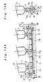
- a fourth embodiment shown in Figs.5A and 5B is an apparatus which regulates the discharge pressure using a discharge pressure regulating device similar to the air pouch shown in the first embodiment, although a feature of this embodiment is that by providing a plurality of material supply sections 1, and sharing a chamber 11a and a tube shaped air pouch 11b, the discharge pressure within a predetermined capacity is regulated in a single batch by the single discharge pressure regulating device.
- a squeegee 37 is used for filling an opening 35 in a screen 34 positioned on the circuit board 32 with the viscous material 31, but in the present embodiment, instead of the squeegee 37, a thin blade (inclined plate) 12 described below is used under the operation of the aforementioned discharge pressure regulating device.
- a viscous material application apparatus is used as the print head of a screen printing machine.
- the viscous material 31 in the printing step where the viscous material 31 is used to fill the opening 35 in the screen 34, by increasing or decreasing the capacity of the chamber 11a by utilizing the gas intake and exhausting actions associated with the air pouch 11b positioned along the alignment direction of the material supply sections 1 and the discharge pressure regulating device (air supply section) 2 positioned in a single location at one end of the apparatus, highly accurate discharge pressure adjustments are performed for maintaining the filling pressure of the viscous material 31 entering the opening 35 at a suitable value, enabling an improvement in the printing quality.
- this viscous material application apparatus has a length of 270mm, and the viscous material 31 is stored in material supply sections 1, with one positioned centrally and the others positioned with a 85mm separation to the left and the right, respectively.
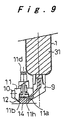
- the viscous material 31 is transferred under pressure from a through aperture 9a with diameter of approximately 6mm inside a joint 9 connected to the material supply section 1, into the chamber 11a inside the application unit 11.
- the chamber 11a is provided with an air port 11d for supplying compressed air from the air supply section 2, a joint 11e, and the air pouch 11b.
- a shaft 11g and a pipe 11f with air holes for the intake or exhausting of air are mounted inside the air pouch 11b. Because the length of the discharge port 14, at 270mm, is quite long, the shaft 11g is provided to enable air to be transferred evenly and instantaneously into the air pouch 11b, thereby preventing the air pouch 11b, which is made of nylon tube of 0.05mm in thickness, from deforming and protruding outside the chamber 11a.
- the joint 11e is connected to the pipe 11f.
- the air pouch 11b has a diameter of approximately 10mm and a length of approximately 220mm, and is connected to the joint 11e using an O-ring or the like to prevent air leaks.
- Two thin blades 12 made of thin copper blades of 0.3mm in thickness are attached at both sides at the bottom of the chamber 11a, and are held in position by blade weights 10 so as to approach one another in a downward direction leaving a spacing of approximately 10mm, and in screen printing this arrangement replaces the conventional squeegee.
- the opening between the two thin blades 12, 12 forms the discharge port 14, and the viscous material 31 is discharged through this discharge port 14.
- Side plates 13 are fixed to the chamber 11a with side stoppers 15 of urethane rubber or the like disposed therebetween, to prevent the viscous material 31 from leaking out of the chamber 11a.
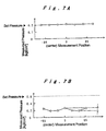
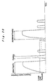
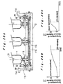
- the variation in the fourth embodiment was approximately 0.01kgf/cm 2 , as shown in Fig.7A, and can effectively be ignored.
- the variation in the conventional apparatus was approximately 0.1kgf/cm 2 , as shown in Fig.7B.
- the viscous material 31 is pressurized inside the chamber 11a uniformly, and with a high degree of accuracy, and the viscous material 31 discharged from the discharge port 14 is applied uniformly along the length of the discharge port 14.
- the discharge pressure is varied at each of the application positions.
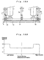
- material supply sections 1 are provided in two locations as shown in Fig.10A, and air pouches 3f, 3e, 3g are provided in three locations in the central section and at the left and right sections, and are arranged with separate air ports 3a which interconnect with air supply sections 2.
- the discharged viscous material has a high viscosity of approximately 200Pa ⁇ s, such as a printing paste
- the air pressure for the compressed air from the left hand and right hand air supply sections 2 to 0.5kgf/cm 2 and setting the value for the central section to 0.3kgf/cm 2
- the discharge pressure from the chamber 3c is subjected to localized pressure regulation at the left section, the right section and the central section, as shown in Fig.10B.
- the chamber 3c could also be partitioned in accordance with the air supply sections 2.
- the plurality of air pouches 3e, 3f, 3g need not necessarily be positioned in a straight line as in the apparatus described above, and in a sixth embodiment shown in Fig.11A, by arranging a plurality of air pouches 3b in parallel, the discharge pressure is varied within a single application unit 3, and a desired pressure distribution is created.
- Fig.11B is a graph showing that pressure distribution.
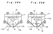
- Fig.12A and Fig.12B are diagrams showing the suction action on the viscous material 31 when the discharge port 14 is moved away from the application target 32 following discharge of the viscous material 31 from the viscous material application apparatus and application of that viscous material onto the application target 32, for the apparatus of the embodiment 4 and the embodiment 5.
- the viscous material 31 near the discharge port 14 is pulled apart between the application target 32 and the discharge port 14, and a portion of the viscous material 31b is applied to the application target 32, and the remaining viscous material 31a is left hanging down from the discharge port 14.
- Fig.12B by suctioning air from the air pouch 11b via the pipe 11f with air holes, the air pouch 11b contracts and the viscous material 31a hanging down is returned to the inside of the chamber 11a.
- the viscous material 31 adheres to the area surrounding the discharge port 14 (the surfaces of the opening to the chamber 11a).
- the dangling viscous material 31a is suctioned inside the chamber 11a using air suction such as that described above, then even if the discharge port 14 is repositioned on top of the application target 32 for reprinting, the viscous material 31 does not protrude out, and the surface of the application target 32 is kept in a clean state.
- the pressure required for performing this suction is supplied by the air supply section 2, and the pressure for the suction action need only be sufficient to contract the air pouch 11b, with values of -0.2kgf/cm 2 to -0.3kgf/cm 2 being suitable.
- Fig.13 shows a seventh embodiment.
- supply of the viscous material 5 to the chamber 3c formed inside the application unit 3 was carried out using compressed air, but the supply device is not restricted to this configuration.
- the application unit 3 is formed so as to be detachable from the air pouch 3b, and supply of the viscous material 5 is carried out by exchanging this application unit 3 with a new application unit 3 filled with the viscous material 5.
- Supply of the viscous material 5 may also be carried out by exchanging a cartridge 3h formed such as to be accommodated within the chamber 3c. In such a case, the internal space of the cartridge 3h forms the chamber (pressurized chamber) inside the application unit 3.
- the material of the cartridge 3h may be any material capable of being accommodated in the chamber 3c such as nylon, a fluorine based system, a metal system, or a non-metal system.
- An eighth embodiment shown in Fig.14A and Fig.14B is an apparatus in which the discharge pressure is regulated using a discharge pressure regulating device similar to the air pouch 11b shown in the fourth embodiment, wherein a plurality of aligned material supply sections 1 share a chamber 11a and an air pouch 11b, the discharge pressure within a predetermined capacity is regulated in a single batch using the single discharge pressure regulating device, and a soft elastic material 38 is inserted between the lower side surfaces of the chamber 11a and the thin blades (inclined plates) 12.
- the adhesion to the screen can be improved, and any leakage of the viscous material 31 from between the thin blades 12 and the screen can be prevented.
- the thin blades 12 need to be lengthened and the flexion of the thin blades 12 increased.
- such lengthening causes the capacity of the chamber 11a to increase and the amount of supplied viscous material 31 to increase, which invites an increase in the supply time and an increase in the weight of the application unit 11.
- the soft elastic material 38 is constructed along the thin blades 12, and may be connected at the edges of the two thin blades 12 forming a single integrated unit, as shown in numeral 38a of Fig.15A, or alternatively may be divided into a pair of left and right soft elastic materials 38b formed along the thin blades 12 and another pair of soft elastic materials 38c formed at the two edges of the thin blades 12, as shown in Fig.15B.
- the soft elastic material 38 need not be formed along the thin blades 12, and the soft material 38 is inserted only at the two edges of the thin blades 12. Furthermore, the soft elastic material 38 may be fixed to the chamber 11a, or may also be simply inserted between the chamber 11a and the thin blades 12 or a separate plate from the edges of the thin blades 12. Furthermore, the flexion of the thin blades 12 could also be ensured by reducing the thickness of the thin blades 12 or by using a resin based material.
- a viscous material application apparatus of this embodiment when used as a print head in a screen printing machine, by allowing a large degree of flexion for the thin blades 12, any waviness or the like within the screen is followed, and the viscous material 31 is scraped with the thin blades 12 even if there is no circuit board beneath the screen.
- the application unit 11 is often configured to enable free movement up and down to enable the screen to be followed, although restricting the up and down movement of the application unit 11 in order to effectively utilize the flexion of the thin blades 12 is preferable in that it enables the thin blades 12 to move up and down and the viscous material 31 to be scraped.
- the soft elastic material 38 in addition to being soft, should preferably be solvent resistant, and suitable materials include a soft polyethylene or urethane rubber for example, although if the material is to be exchanged periodically, then silicon rubber and more particularly foam based silicon rubber, which is a soft material, is also suitable.
- a material with a high degree of hardness such as fluorine based material is joined to, or coated onto the surface of the soft elastic material 38 facing the screen, then the slipperiness is improved and the life of the soft elastic material 38 is extended.
- FIG.16A Next is a comparison of pressure levels within the chamber 11a using Fig.16A and Fig.16B.
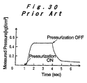
- the viscous material 31 inside the chamber 11a retains a certain amount of pressure (hereafter referred to as the residual pressure) even though the supply pressure has been cut, and this residual pressure does not decrease significantly even after several minutes have passed.
- the discharge pressure is generated by the air pouch 11b, and although the discharge pressure can be controlled by the air pouch 11b in those cases where the residual pressure is smaller than the discharge pressure, control of the discharge pressure becomes difficult in those cases where the residual pressure is larger than the discharge pressure.
- the air pouch 11b is inflated when supply pressure is applied to the material supply section 1, or during the supply process, and then when the supply pressure is cut at the point the inside of the chamber 11a becomes filled with the viscous material 31, if the air for the air pouch 11b is also cut, the deflation of the air pouch 11b enables the residual pressure within the chamber 11a to be absorbed, and as shown in Fig.16B, the residual pressure inside the chamber 11a is reduced within a period of no more than 1 second. Consequently, the pressure within the chamber 11a disappears, and the discharge pressure is controlled by the air pouch 11b.
- the air pouch 11b may be provided in a separate chamber 11m from the chamber 11a so as not to inhibit the movement of the viscous material 31 within the chamber 11a (in such a case, the pressurized chamber of the present invention includes both 11a and 11m), or alternatively similar effects are achieved by providing the air pouch 11b in the upper portion of the chamber 11a.
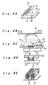
- the air pouches 11b described up until this point have had a circular cross section (Fig.17A), although the same effects are obtained using an air pouch 39a which collects air in a sheet like shape such as that shown in Fig.17B, or an air pouch 39b which collects air in a bag type arrangement such as that shown in Fig.17C.
- the same effects are also obtained by forming the pressurized chamber (chamber) 11a in a pouch shape, and using an elastic material pouch (air pouch) 39c so that the region the air enters becomes a chamber, as shown in Fig.17D.
- the description outlined an apparatus in which the thin blades were made of copper with a thickness of 0.3mm, but copper, stainless steel or resin (polyimide or combination of polyamide and polyimide or the like) plates with an approximate thickness of 0.1mm to 0.5mm may also be used.
- the left and right joints 9 between the material supply sections 1 and the application unit 11 were positioned in the upper portion of the application unit 11 as shown in Fig.5, but these joints may also be positioned on the left and right side surfaces of the application unit 11, as shown in Fig.33, with the viscous material 31 from the material supply sections 1 being supplied from the side surface of the chamber 11a. So doing enables the supply of the viscous material 31 to the chamber 11a to be carried out smoothly.
- the supply pressure may be applied for a predetermined length of time, although by providing at least one pressure detecting member 41 either on an inside edge of the chamber 11a or between the chamber 11a and the material supply section 1, the state where the chamber 11a is filled with the viscous material 31 is detected using the pressure detecting member 41.
- the method for the initial supply of the viscous material 31 into the chamber 11a is the same as that described above, and when the inside of the chamber 11a is full, the air pouches 11b, 39a, 39b, 39c (hereafter recorded as simply 11b) are inflated and printing is started. As the printing occurs, the amount of the viscous material 31 gradually decreases, but as long as the air pouch 11b is inflated, a predetermined pressure is generated inside the chamber 11a and printing is continued.
- the pressure inside the chamber 11a falls, and reaches a preset lower limit pressure necessary for printing.
- the pressure detecting member 41 By detecting the lower limit pressure inside the chamber 11a with the pressure detecting member 41, the reduction in the amount of the viscous material 31 is detected, and by then carrying out the same operations as those used during the initial supply to re-supply the inside of the chamber 11a with the viscous material 31, the air pouch 11b can once again be inflated, enabling a discharge pressure to be generated and the printing to be continued.
- the viscous material 31 may be supplied in accordance with a set timing such as the number of printings, without detecting the lower limit pressure, and in cases where the viscosity of the viscous material 31 is low, a normal low supply pressure may be applied, and the viscous material 31 supplied a little at a time.
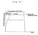
- the pressure inside the chamber 11a during printing is described with reference to Fig.21.
- the pressure inside the chamber 11a is raised instantaneously, and printing is then carried out by moving the application unit 11.
- the pressure detected by the pressure detecting member 41 will be lower than that detected when the application unit 11 is stopped.
- the air pouch 11b can be left inflated at a predetermined pressure, but if problems arise, then the pressure during actual printing should also be detected, and the difference in the pressure inside the chamber 11a between the case when the application unit 11 is stopped and the case when it is moving is used in considering the movement state of the viscous material 31. Particularly in the case where the pressure difference inside the chamber 11a is large, often this indicates the viscous material 31 is easily moved, in other words the case where the viscosity has fallen, and so the pressure of the air pouch 11b needs to be reset in accordance with the degree of this fall in pressure.
- This resetting of the pressure is a way of correcting the relationship with the viscosity of the viscous material 31, and so if the relationship between the viscosity, the detected pressure and the set pressure has already been determined in advance, then this resetting can be performed automatically even during printing. Furthermore even if the viscosity of the viscous material 31 varies with a variation in temperature or with extended usage or the like, by resetting the pressure of the air pouch 11b by conducting a comparison with the pressure measured during the previous printing, stable printing is achieved.
- the pressure state of the viscous material 31 is detected with greater accuracy, and detection of movement of the viscous material 31 inside the chamber 11a also becomes possible. If the pressure difference between the pressure detecting members 41 is large, then the movement of the viscous material 31 is poor, in other words the viscosity is high, and so the pressure of the air pouch 11b (39a) is set to a large value, whereas if the pressure difference between the pressure detecting members 41 is small, then the movement of the viscous material 31 is good, in other words the viscosity is low, and so the pressure of the air pouch 11b is set to a small value.
- this phenomenon is the same as the case where a squeegee 37 is used for printing, and when the squeegee 37 is moved the viscous material 31 undergoes a circulating flow in the same direction.
- the viscous material 31 is stirred frequently inside the vessel, before being supplied to the squeegee 37.
- the viscous material 31 is unable to be stirred prior to supplying, but considering that the viscous material 31 inside the chamber 11a flows during the printing operation, it is clear that the viscous material 31 is stirred prior to the commencement of printing by moving the application unit 11 back and forth across the top of the screen 34 with a discharge pressure applied, and performing this type of operation prior to printing is a suitable technique for stabilizing the printing.
- a shaft 42 is provided inside the chamber 11a so that the viscous material 31 is stirred by rotating this shaft.
- the shaft 42 sits inside the chamber 11a and is supported at both ends, and O-rings 43 prevent the viscous material 31 from leaking out.
- a pulley 44 is fixed to at least one end of the shaft 42, and the pulley 44 is connected to a motor 46 via a belt 45. In other words, by rotating the motor 46, the shaft 42 rotates and the viscous material 31 is forcibly stirred.
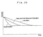
- the viscous material 31 is viewed in terms of viscosity, then during each printing operation the viscous material 31 is flowing and so the viscosity decreases, albeit gradually.
- the viscosity of the viscous material 31 is lowered by a certain amount in advance, although by using the shaft 42, the viscosity is lowered even further and the degree of viscosity variation in the viscous material 31 during subsequent printing is reduced. Needless to say, rotating the shaft 42 while moving the print head 11 back and forth is even more effective.
- the flow velocity of the viscous material 31 during printing is largest at the location of the discharge port 14 and decreases with movement up and away from the discharge port.
- the flow velocity is smaller, and accordingly the flow velocity at the location of the discharge port 14 falls and no longer matches the velocity of the print head 11, which causes slipping between the screen 34 and the viscous material 31, making printing difficult.
- the flow velocity at the location of the discharge port 14 attempts to speed up, but the viscosity of the viscous material 31 inside the chamber 11a acts as resistance and prevents the flow velocity at the discharge port 14 from increasing, and accordingly slipping develops between the screen 34 and the viscous material 31, and printing becomes difficult.
- the shaft 42 may also be freed and allowed to rotate in accordance with the flow of the viscous material 31, and furthermore a strain gauge or the like could also be attached to the end axis of the shaft 42 to enable the viscosity to be measured, but forcibly rotating the shaft 42 is more effective.
- FIG.27A there is the viscous material 31 inside a chamber 11a of the print head 11, and the viscous material 31 contacts the screen 34 at the discharge port 14.
- Fig.27B if the print head 11 is simply lifted in this state, then a large amount of the viscous material 31 is left on the screen 34.
- the present invention by deflating the air pouch 11b inside the chamber 11a the capacity of the space available for storing the viscous material is increased, and by moving the viscous material 31 inside the chamber 11a away from the screen 34, recovery of the viscous material 31 is carried out with ease.
- the viscous material 31 was moved by deflating the air pouch 11b, as described below, but the method for increasing the capacity of the space available for storing the viscous material inside the chamber 11a is not restricted to this method.
- the air pouch 11b is deflated to increase the capacity of the space available for storing the viscous material inside the chamber 11a, and so as shown in Fig.27D, by moving the print head 11 horizontally and scraping up the viscous material 31 on the screen 34 with the thin blades 12, and then lifting the print head 11 up while the horizontal movement is continued as shown in Fig.27E, the print head 11 is separated from the screen 34 without leaving any viscous material 31 on the surface of the screen 34.
- the temperature of the viscous material 31 is rapidly returned to room temperature as shown in Fig.28C, and so production is started earlier and excessive amounts of time and effort are eliminated.
- discharge pressure regulating device positioned near the discharge port enables efficient pressure transmission to occur when a viscous material stored inside a pressurized chamber is discharged, and enables an instantaneous discharge to be carried out at an appropriate and uniform discharge pressure with good efficiency and a high degree of accuracy, and moreover by utilizing the invention in screen printing, the increase in precision of the filling pressure at an opening of the screen enables leakage or bridge generation by the viscous material to be prevented, and so the invention is useful in improving the printing quality.
Landscapes
- Engineering & Computer Science (AREA)
- Manufacturing & Machinery (AREA)
- Microelectronics & Electronic Packaging (AREA)
- Mechanical Engineering (AREA)
- Coating Apparatus (AREA)
- Application Of Or Painting With Fluid Materials (AREA)
Abstract
Description
Claims (19)
- A viscous material application apparatus comprising:wherein the discharge pressure regulating device is provided either inside said pressurized chamber (3c) or facing said pressurized chamber (3c).a main body (3) having a pressurized chamber (3c) for storing a viscous material (5), the pressurized chamber connecting through to a discharge port (4a);a viscous material supply device (1) for transferring said viscous material (5) under pressure to said pressurized chamber (3c); anda discharge pressure regulating device (2, 3b) for regulating a discharge pressure of said viscous material (5) by increasing and decreasing a capacity of said pressurized chamber (3c) when said viscous material (5) inside said pressurized chamber (3c) is pressurized and discharged,
- The viscous material application apparatus according to claim 1, wherein said discharge pressure regulating device (2, 3b) comprises a pouch (3b) which is positioned inside said pressurized chamber (3c) and which increases and decreases in internal capacity through intake and exhausting of gas, and an air supply section (2) for regulating pressure inside said pouch (3b) by either one of supplying gas to, and discharging gas from said pouch (3b).
- The viscous material application apparatus according to claim 1, wherein said discharge pressure regulating device comprises an actuator such as an air cylinder (7) and a voice coil motor (8), and a diaphragm (7b) which transforms under influence of said actuator and increases and decreases capacity inside said pressurized chamber (3c).
- The viscous material application apparatus according to claim 1, wherein a single pressurized chamber (11a), discharge pressure regulating device (2, 11b) and discharge port (14) are shared across a plurality of linearly aligned viscous material supply devices (1), and a discharge pressure of said viscous material (31) at discharge positions along an alignment direction of said viscous material supply devices (1) is regulated in a single batch.
- The viscous material application apparatus according to claim 1, wherein a plurality of discharge pressure regulating devices (2, 3e, 3f, 3g) are used, and a discharge pressure of said viscous material (31) at a discharge position is regulated as desired.
- The viscous material application apparatus according to claim 4, wherein a pair of inclined plates (12, 12) are attached to both sides of a lower section of said pressurized chamber (11a) so as to approach one another in a downward direction, and an opening between bottom edges of said plates (12, 12) is used as a discharge port (14).
- A viscous material application apparatus comprising:wherein the discharge pressure regulating device is provided either inside said pressurized chamber (3c) or facing said pressurized chamber (3c).a main body (3) having a pressurized chamber (3c) therein, the pressurized chamber for storing a viscous material (5), and connecting through to a discharge port (4a); anda discharge pressure regulating device (3b) for regulating a discharge pressure of said viscous material (5) by increasing and decreasing a capacity of said pressurized chamber (3c) when said viscous material (5) inside said pressurized chamber (3c) is pressurized and discharged,
- The viscous material application apparatus according to claim 6, wherein a soft elastic material (38) is inserted between each of said inclined plates (12, 12) and a lower side surface of said pressurized chamber (11a).
- The viscous material application apparatus according to claim 2, wherein following filling of said pressurized chamber (3c) with said viscous material (5) using said viscous material supply device (1), residual supply pressure remaining inside said pressurized chamber (3c) is absorbed by said pouch (3b).
- The viscous material application apparatus according to claim 4, wherein a pressure detecting member (41) is provided at either one of an inside edge of said pressurized chamber (11a) and a position between the pressurized chamber and said viscous material supply device (1), and said pressure detecting member (41) detects when said pressurized chamber (11a) is filled with said viscous material (31).
- The viscous material application apparatus according to claim 10, wherein when said pressurized chamber (11a) is pressurized by said discharge pressure regulating device (2, 11b), in cases where a detected pressure at said pressure detecting member (41) does not reach a predetermined pressure, an amount of viscous material (31) is judged to be insufficient, and said viscous material (31) is supplied by said viscous material supply device (1).
- The viscous material application apparatus according to claim 10, wherein said pressurized chamber (11a) is moved while pressurized by said discharge pressure regulating device (2, 11b), and a pressure of said discharge pressure regulating device (2, 11b) is regulated based on a pressure of said pressurized chamber (11a) detected with said pressure detecting member (41).
- The viscous material application apparatus according to claim 4, wherein a rotatable shaft (42) is provided in said pressurized chamber (11a), and said viscous material (31) is mobilized by rotating said shaft (42).
- The viscous material application apparatus according to claim 4, wherein said viscous material (31) is recovered into said pressurized chamber (11a) by setting a pressure of said pressurized chamber (11a) to a negative pressure by said discharge pressure regulating device (2, 11b), and lifting said pressurized chamber (11a) while moving said chamber (11a) horizontally.
- The viscous material application apparatus according to claim 2, wherein a temperature of said viscous material (31) is stabilized by exchanging gas inside said pouch (11b).
- A screen printing machine comprising the viscous material application apparatus according to claim 6 as a print head (11).
- A viscous material application method for applying a viscous material (31) to an application target by moving an application unit (11) holding said viscous material (31) inside a chamber (11a) across said application target while discharging said viscous material (31),
wherein said viscous material (31) is moved to inside said application unit (11) and recovered into said application unit (11). - A viscous material application method for discharging and applying a viscous material (31) to an application target by moving an application unit (11) holding said viscous material (31) inside a chamber (11a) across said application target while increasing and decreasing a capacity of space available for storage of said viscous material inside said chamber (11a),
wherein said viscous material (31) is recovered into said application unit (11) by moving said application unit (11) along said application target, and lifting said application unit (11) up from said application target while increasing said capacity of space available for storage of said viscous material inside said chamber (11a) of said application unit (11). - A viscous material application method for discharging and applying a viscous material (31) to an application target by moving an application unit (11) holding said viscous material (31) inside a chamber (11a) across said application target while applying pressure to said viscous material (31),
wherein said viscous material (31) is recovered into said application unit (11) by moving said application unit (11) along said application target, and lifting said application unit (11) up from said application target while increasing a capacity of space available for storage of said viscous material inside said chamber (11a) of said application unit (11).
Applications Claiming Priority (3)
| Application Number | Priority Date | Filing Date | Title |
|---|---|---|---|
| JP14106999 | 1999-05-21 | ||
| JP14106999A JP3949315B2 (en) | 1998-10-23 | 1999-05-21 | Viscous material coating apparatus and viscous material coating method |
| PCT/JP2000/001513 WO2000071264A1 (en) | 1999-05-21 | 2000-03-13 | Viscous material applicator |
Publications (2)
| Publication Number | Publication Date |
|---|---|
| EP1197267A1 true EP1197267A1 (en) | 2002-04-17 |
| EP1197267A4 EP1197267A4 (en) | 2006-09-20 |
Family
ID=15283525
Family Applications (1)
| Application Number | Title | Priority Date | Filing Date |
|---|---|---|---|
| EP00908039A Withdrawn EP1197267A4 (en) | 1999-05-21 | 2000-03-13 | APPLICATION DEVICE FOR VISCOUS MATERIALS |
Country Status (4)
| Country | Link |
|---|---|
| US (2) | US6736291B1 (en) |
| EP (1) | EP1197267A4 (en) |
| KR (1) | KR100644502B1 (en) |
| WO (1) | WO2000071264A1 (en) |
Cited By (4)
| Publication number | Priority date | Publication date | Assignee | Title |
|---|---|---|---|---|
| WO2004037439A1 (en) * | 2002-10-23 | 2004-05-06 | 3M Innovative Properties Company | Coating die with expansible chamber device |
| WO2004087421A1 (en) * | 2003-03-28 | 2004-10-14 | Speedline Technologies, Inc. | Pressure control system for printing a viscous material |
| WO2006131184A1 (en) * | 2005-06-07 | 2006-12-14 | Sca Schucker Gmbh & Co. Kg | Method for applying strips of pasty material |
| WO2013119726A1 (en) * | 2012-02-08 | 2013-08-15 | Illinois Tool Works Inc. | Print head for stencil printer |
Families Citing this family (23)
| Publication number | Priority date | Publication date | Assignee | Title |
|---|---|---|---|---|
| EP1895279A1 (en) * | 2006-08-28 | 2008-03-05 | Nestec S.A. | Multiple channel valve unit |
| US7980197B2 (en) * | 2006-11-03 | 2011-07-19 | Illinois Tool Works, Inc. | Method and apparatus for dispensing a viscous material on a substrate |
| US8087549B2 (en) * | 2006-11-13 | 2012-01-03 | Yokogawa Electric Corporation | Liquid supply apparatus and method of detecting fault thereof |
| JP5460132B2 (en) * | 2009-06-03 | 2014-04-02 | 武蔵エンジニアリング株式会社 | Liquid dispensing method and apparatus |
| US8794491B2 (en) * | 2011-10-28 | 2014-08-05 | Nordson Corporation | Dispensing module and method of dispensing with a pneumatic actuator |
| CN103286043A (en) * | 2013-06-26 | 2013-09-11 | 肖根福罗格注胶技术(苏州工业园区)有限公司 | Feeding pressurization device |
| EP3078441B8 (en) * | 2013-12-05 | 2018-11-21 | FUJI Corporation | Solder supply device |
| US9802264B2 (en) * | 2013-12-18 | 2017-10-31 | Fuji Machine Mfg. Co., Ltd. | Solder supply device including a sensor to detect movement of a solder container |
| WO2016073761A1 (en) * | 2014-11-05 | 2016-05-12 | 3M Innovative Properties Company | Die for coating suspensions with flow obstruction device and method of use |
| KR20170089053A (en) * | 2016-01-25 | 2017-08-03 | 삼성전자주식회사 | Resin coating apparatus and method of manufacturing light emitting device package using the same |
| WO2018050482A1 (en) * | 2016-09-13 | 2018-03-22 | Chemetall Gmbh | Device and method for dynamic metering of sealing compounds |
| KR101899243B1 (en) * | 2017-03-30 | 2018-09-14 | 주식회사 프로텍 | Stroke Control Type Viscous Liquid Pump |
| KR101916575B1 (en) * | 2017-03-30 | 2018-11-07 | 주식회사 프로텍 | Flowrate Measuring Type Viscous Liquid Pump |
| KR102376418B1 (en) * | 2017-04-14 | 2022-03-17 | 일리노이즈 툴 워크스 인코포레이티드 | Automatic Solder Paste Applicator for Solder Paste Printer |
| TWI759460B (en) * | 2017-04-14 | 2022-04-01 | 美商伊利諾工具工程公司 | A device for preventing dripping of solder paste |
| WO2018189586A2 (en) * | 2017-04-14 | 2018-10-18 | 伊利诺斯工具制品有限公司 | A solder paste feeding component and method |
| TWI789552B (en) * | 2018-11-26 | 2023-01-11 | 美商伊利諾工具工程公司 | A stencil printer |
| CN109395975A (en) * | 2018-12-25 | 2019-03-01 | 肖根福罗格注胶技术(苏州工业园区)有限公司 | Glue glue injecting head for the high filler of high viscosity |
| US20220323985A1 (en) * | 2019-10-07 | 2022-10-13 | Threebond Co., Ltd. | Dispensing apparatus, movable member, circulation control method |
| CN110976221A (en) * | 2020-01-06 | 2020-04-10 | 永康本元塑料制品有限公司 | Film coating device for coating polyester plastic on wire |
| JP6808304B1 (en) * | 2020-01-14 | 2021-01-06 | 中外炉工業株式会社 | Coating device |
| WO2021174032A1 (en) | 2020-02-28 | 2021-09-02 | Illinois Tool Works Inc. | Piston monitoring assembly |
| CN117038223B (en) * | 2023-09-18 | 2024-03-29 | 安邦电气股份有限公司 | A kind of special cable processing equipment for traffic engineering machinery |
Family Cites Families (24)
| Publication number | Priority date | Publication date | Assignee | Title |
|---|---|---|---|---|
| US3227136A (en) * | 1961-10-26 | 1966-01-04 | Eastman Kodak Co | Extrusion coating apparatus |
| US3240390A (en) * | 1963-10-25 | 1966-03-15 | John Wood Company | Solenoid pilot valve |
| US3507583A (en) * | 1967-10-04 | 1970-04-21 | Gen Aniline & Film Corp | Pump for liquids |
| DE2300289C2 (en) * | 1973-01-04 | 1985-01-10 | Mitter & Co, 4815 Schloss Holte | Device for applying liquid or pasty paint for screen printing machines |
| US4674658A (en) * | 1985-09-04 | 1987-06-23 | Risdon Corporation | Fluid dispenser |
| US4622239A (en) * | 1986-02-18 | 1986-11-11 | At&T Technologies, Inc. | Method and apparatus for dispensing viscous materials |
| JPS6377668A (en) | 1986-09-19 | 1988-04-07 | 株式会社日立製作所 | Method of driving screw |
| JPS6377668U (en) * | 1986-11-12 | 1988-05-23 | ||
| US4938994A (en) | 1987-11-23 | 1990-07-03 | Epicor Technology, Inc. | Method and apparatus for patch coating printed circuit boards |
| CH675216A5 (en) * | 1987-11-30 | 1990-09-14 | Alphasem Ag | |
| US5167837A (en) * | 1989-03-28 | 1992-12-01 | Fas-Technologies, Inc. | Filtering and dispensing system with independently activated pumps in series |
| FR2657430B1 (en) * | 1990-01-23 | 1994-02-25 | Roland Torterotot | DOSER-DISPENSER AND METHOD FOR DOSING A PASTY AND / OR LIQUID PRODUCT. |
| US5186982A (en) * | 1990-09-18 | 1993-02-16 | Minnesota Mining And Manufacturing Company | Pin transfer applicator and method |
| US5207352A (en) * | 1991-04-19 | 1993-05-04 | Nordson Corporation | Method and apparatus for dispensing high viscosity fluid materials |
| DE4119415A1 (en) * | 1991-06-13 | 1992-12-17 | Huebers Verfahrenstech | METHOD FOR TRANSPORTING AND PREPARING AND FILLING A CASTING SYSTEM WITH CASTING RESIN, AND DEVICE FOR IMPLEMENTING THE PROCESS |
| IE930532A1 (en) * | 1993-07-19 | 1995-01-25 | Elan Med Tech | Liquid material dispenser and valve |
| JPH06170304A (en) * | 1992-12-11 | 1994-06-21 | Toshiba Seiki Kk | Adhesive applicator and method for pellet bonding |
| US5467899A (en) * | 1994-02-08 | 1995-11-21 | Liquid Control Corporation | Dispensing device for flowable materials |
| JPH09164357A (en) * | 1995-12-18 | 1997-06-24 | Dainippon Screen Mfg Co Ltd | Liquid coating device |
| US5799833A (en) * | 1996-06-19 | 1998-09-01 | Abc Dispensing Technologies | Germicide dispensing system |
| JPH1099756A (en) * | 1996-10-01 | 1998-04-21 | Fuji Mach Mfg Co Ltd | Adhesive dispenser |
| US5927560A (en) * | 1997-03-31 | 1999-07-27 | Nordson Corporation | Dispensing pump for epoxy encapsulation of integrated circuits |
| US5887768A (en) * | 1998-04-27 | 1999-03-30 | Vital Signs Inc | Apparatus for dispensing liquid with liquid retention |
| KR100280770B1 (en) * | 1999-02-18 | 2001-01-15 | 조현기 | Apparatus for dispensing photoresister on semiconductor device |
-
2000
- 2000-03-13 WO PCT/JP2000/001513 patent/WO2000071264A1/en not_active Ceased
- 2000-03-13 KR KR1020017014837A patent/KR100644502B1/en not_active Expired - Fee Related
- 2000-03-13 EP EP00908039A patent/EP1197267A4/en not_active Withdrawn
- 2000-03-13 US US09/926,588 patent/US6736291B1/en not_active Expired - Fee Related
-
2004
- 2004-03-16 US US10/800,748 patent/US7464838B2/en not_active Expired - Fee Related
Cited By (16)
| Publication number | Priority date | Publication date | Assignee | Title |
|---|---|---|---|---|
| CN1688395B (en) * | 2002-10-23 | 2012-11-28 | 3M创新有限公司 | Coating die with expansible chamber device |
| WO2004037439A1 (en) * | 2002-10-23 | 2004-05-06 | 3M Innovative Properties Company | Coating die with expansible chamber device |
| US7344665B2 (en) | 2002-10-23 | 2008-03-18 | 3M Innovative Properties Company | Coating die with expansible chamber device |
| US7524377B2 (en) | 2002-10-23 | 2009-04-28 | 3M Innovative Properties Company | Coating die with expansible chamber device |
| US7685693B2 (en) | 2002-10-23 | 2010-03-30 | 3M Innovative Properties Company | Method of forming coating die with expansible chamber device |
| KR101018900B1 (en) * | 2002-10-23 | 2011-03-02 | 쓰리엠 이노베이티브 프로퍼티즈 컴파니 | Sheathing die with inflatable chamber mechanism |
| WO2004087421A1 (en) * | 2003-03-28 | 2004-10-14 | Speedline Technologies, Inc. | Pressure control system for printing a viscous material |
| US6955120B2 (en) | 2003-03-28 | 2005-10-18 | Speedline Technologies, Inc. | Pressure control system for printing a viscous material |
| GB2415409A (en) * | 2003-03-28 | 2005-12-28 | Speedline Technologies Inc | Pressure control system for printing a viscous material |
| GB2415409B (en) * | 2003-03-28 | 2007-01-24 | Speedline Technologies Inc | Pressure control system for printing a viscous material |
| CN100406253C (en) * | 2003-03-28 | 2008-07-30 | 斯皮德莱技术公司 | Stencil printer and printing head for printing viscous materials |
| WO2006131184A1 (en) * | 2005-06-07 | 2006-12-14 | Sca Schucker Gmbh & Co. Kg | Method for applying strips of pasty material |
| DE102005026374B4 (en) * | 2005-06-07 | 2017-10-12 | Sca Schucker Gmbh & Co. Kg | Process for applying strips of pasty material |
| WO2013119726A1 (en) * | 2012-02-08 | 2013-08-15 | Illinois Tool Works Inc. | Print head for stencil printer |
| US8939073B2 (en) | 2012-02-08 | 2015-01-27 | Illinois Tool Works Inc. | Print head for stencil printer |
| US9126280B2 (en) | 2012-02-08 | 2015-09-08 | Illinois Tool Works Inc. | Print head for stencil printer |
Also Published As
| Publication number | Publication date |
|---|---|
| US7464838B2 (en) | 2008-12-16 |
| US6736291B1 (en) | 2004-05-18 |
| EP1197267A4 (en) | 2006-09-20 |
| US20040173633A1 (en) | 2004-09-09 |
| KR20020007417A (en) | 2002-01-26 |
| WO2000071264A1 (en) | 2000-11-30 |
| KR100644502B1 (en) | 2006-11-10 |
Similar Documents
| Publication | Publication Date | Title |
|---|---|---|
| US6736291B1 (en) | Viscous material application apparatus | |
| US9421784B2 (en) | Liquid ejecting apparatus | |
| US6626097B2 (en) | Apparatus for dispensing material in a printer | |
| US6955120B2 (en) | Pressure control system for printing a viscous material | |
| JP2012152931A (en) | Inkjet printing apparatus | |
| CN107427857B (en) | Fluid discharge device, fluid discharge method, and fluid application device | |
| JP2000312851A (en) | Adhesive discharge device | |
| US6772937B2 (en) | Method and apparatus for applying viscous material | |
| JP3949315B2 (en) | Viscous material coating apparatus and viscous material coating method | |
| JP3590298B2 (en) | Method and apparatus for discharging liquid at high speed and precision | |
| JP2002316401A (en) | Viscous material coating method and device | |
| JP3590300B2 (en) | Method and apparatus for discharging liquid at high speed and precision | |
| JP5529003B2 (en) | Liquid supply apparatus and liquid supply method | |
| JP4871093B2 (en) | Method, apparatus and program for filling liquid material | |
| EP4454885A1 (en) | Droplet discharging device and maintenance method | |
| JP3811592B2 (en) | Viscous material supply method | |
| JP2000189875A5 (en) | Viscous material coating apparatus, viscous material coating method, screen printing machine and screen printing method | |
| JP2008114128A (en) | Liquid material filling method, apparatus and program | |
| JPH07204558A (en) | Adhesive coating device | |
| JP7166018B2 (en) | Coating device | |
| KR100861611B1 (en) | printer | |
| JP2001300389A (en) | Viscous material coating method and device | |
| JP2009078201A (en) | Viscous fluid application device | |
| JPH11254641A (en) | Print paste printing apparatus and printing method | |
| JP2006088042A (en) | Liquid applying apparatus and liquid applying method |
Legal Events
| Date | Code | Title | Description |
|---|---|---|---|
| PUAI | Public reference made under article 153(3) epc to a published international application that has entered the european phase |
Free format text: ORIGINAL CODE: 0009012 |
|
| 17P | Request for examination filed |
Effective date: 20011211 |
|
| AK | Designated contracting states |
Kind code of ref document: A1 Designated state(s): AT BE CH CY DE DK ES FI FR GB GR IE IT LI LU MC NL PT SE |
|
| RBV | Designated contracting states (corrected) |
Designated state(s): DE |
|
| A4 | Supplementary search report drawn up and despatched |
Effective date: 20060818 |
|
| 17Q | First examination report despatched |
Effective date: 20080305 |
|
| RAP1 | Party data changed (applicant data changed or rights of an application transferred) |
Owner name: PANASONIC CORPORATION |
|
| GRAP | Despatch of communication of intention to grant a patent |
Free format text: ORIGINAL CODE: EPIDOSNIGR1 |
|
| RIC1 | Information provided on ipc code assigned before grant |
Ipc: H05K 3/10 20060101ALI20090325BHEP Ipc: H05K 3/34 20060101ALI20090325BHEP Ipc: B05D 1/26 20060101ALI20090325BHEP Ipc: B05C 5/02 20060101AFI20090325BHEP Ipc: H05K 3/12 20060101ALI20090325BHEP |
|
| STAA | Information on the status of an ep patent application or granted ep patent |
Free format text: STATUS: THE APPLICATION IS DEEMED TO BE WITHDRAWN |
|
| 18D | Application deemed to be withdrawn |
Effective date: 20090918 |