EP1197019B1 - Method and apparatus for selecting a satellite signal - Google Patents
Method and apparatus for selecting a satellite signal Download PDFInfo
- Publication number
- EP1197019B1 EP1197019B1 EP00944831A EP00944831A EP1197019B1 EP 1197019 B1 EP1197019 B1 EP 1197019B1 EP 00944831 A EP00944831 A EP 00944831A EP 00944831 A EP00944831 A EP 00944831A EP 1197019 B1 EP1197019 B1 EP 1197019B1
- Authority
- EP
- European Patent Office
- Prior art keywords
- ird
- signal
- satellite
- switch
- decoder
- Prior art date
- Legal status (The legal status is an assumption and is not a legal conclusion. Google has not performed a legal analysis and makes no representation as to the accuracy of the status listed.)
- Expired - Lifetime
Links
Images


Classifications
-
- H—ELECTRICITY
- H04—ELECTRIC COMMUNICATION TECHNIQUE
- H04N—PICTORIAL COMMUNICATION, e.g. TELEVISION
- H04N7/00—Television systems
- H04N7/20—Adaptations for transmission via a GHz frequency band, e.g. via satellite
-
- H—ELECTRICITY
- H04—ELECTRIC COMMUNICATION TECHNIQUE
- H04H—BROADCAST COMMUNICATION
- H04H40/00—Arrangements specially adapted for receiving broadcast information
- H04H40/18—Arrangements characterised by circuits or components specially adapted for receiving
- H04H40/27—Arrangements characterised by circuits or components specially adapted for receiving specially adapted for broadcast systems covered by groups H04H20/53 - H04H20/95
- H04H40/90—Arrangements characterised by circuits or components specially adapted for receiving specially adapted for broadcast systems covered by groups H04H20/53 - H04H20/95 specially adapted for satellite broadcast receiving
Definitions
- the present invention relates to a Direct Broadcast Satellite (DBS) system. More particularly, the invention relates to a method and apparatus for selecting one of a plurality of information signals broadcast from at least one satellite in the Direct Broadcast Satellite (DBS) system.
- DBS Direct Broadcast Satellite
- Direct Broadcast Satellite (DBS) content providers have chosen to use multiple satellite networks to distribute their signals.
- a Low Noise Block converter (LNB) supply voltage (+ 13V/+ 18V) has been used to select between the two polarities of signals that were available on a single satellite network. Additionally, if signals from only two satellites are available for reception, then the presence or absence of a 22 KHz tone superimposed on the LNB supply voltage may be used to switch between either of the two satellite networks.
- LNB Low Noise Block converter
- IRD integrated receiver/decoder
- DISEQ satellite selector switch
- the IRD sends a command signal to the selector switch to switch to a selected satellite network.
- the two-way (bi-directional) protocol provides an avenue for feedback from the switch to the IRD.
- the selector switch upon switching, sends an acknowledgement message back to the IRD.
- the lack of feedback may cause a problem if the user disconnects and reconnects the transmission coaxial cable, for example, in an attempt to reset the IRD and switch.
- the IRD will search for the lost satellite signal throughout each of the satellite networks by attempting to send messages to the switch, even though the switch is not connected to the IRD.
- the switch will default to the prior transponder, which is not necessarily the transponder the IRD was expecting to switch to. Thus, the user will receive the wrong satellite signal.
- the lack of feedback from the switch may cause a problem when the IRD sends a command signal that is degraded or incomplete (e.g., coaxial cable signal losses).
- the switch may fail to properly select the correct transponder on a satellite or the correct satellite thereby sending the user an incorrect satellite signal.
- a user selects a satellite signal via an integrated receiver/decoder (IRD), from at least one satellite network.
- IRD integrated receiver/decoder
- the IRD sends a command signal to a selector switch to switch to one of a plurality of low noise block converters (LNB) coupled to a satellite collector dish.
- LNB low noise block converters
- the command signal is transmitted from the IRD whenever the integrated receiver/decoder has not locked on to the satellite signal. Once the IRD acquires the satellite signal, the IRD repeats the transmission of the command signal to the selector switch. Thus, in the event that the selector switch failed to switch to the LNB corresponding to the initial command signal, then the repeated command signal helps to ensure that the selector switch switches to the LNB corresponding with the latest command signal sent by the IRD.
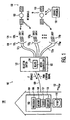
- FIG. 1 depicts a block diagram of a direct broadcast satellite communications system 100.
- the direct broadcast satellite (DBS) system 100 comprises a service provider 130 from which audio, video, and/or data may be (hereinafter "satellite signal") uplinked to a satellite network comprising at least one satellite network 132.
- Each satellite network 132 includes a satellite 133 having a plurality of transponders for downlinking the satellite signal to a plurality of subscriber equipment 102 having satellite signal receiving capabilities. Subscriber equipment 102 for a single location is depicted in FIG. 1 .
- a DBS service provider 130 provides hundreds of television channels including a program guide from which a subscriber may choose programming.
- the subscriber may select any channel via an input device 103 such as a remote control, for tuning an integrated receiver/decoder (IRD) 104 to the carrier frequency of the selected satellite signal.
- IRD integrated receiver/decoder
- the direct broadcast satellite system 100 in conjunction with a method of requesting a satellite signal by a subscriber, as will be described in more detail hereinafter, advantageously ensures that the correct satellite signal is selected and coupled to the IRD 104.
- the subscriber equipment 102 comprises the IRD 104 having a processor 106, a tuner 107, memory 108, and a datalink 105.
- the datalink 105 is utilized in a digital IRD 104.
- the tuner 107 tunes to a desired transponder frequency and down-converts that frequency to a baseband signal (e.g., approaching zero cycles/sec.)
- the baseband signals are sent to the datalink 105 where the baseband signals are converted from an analog to digital data format.
- the digital data is then sent to the memory 107 and processor 106 for storage and further processing, respectfully.
- the IRD 104 is coupled to a selector switch 120, via a signal path 109 such as a coaxial cable or a common transmission line.
- the selector switch 120 comprises a controller 122 such as a microcontroller, and a plurality of switching devices 124 such as relays.
- the processor 106 of the IRD 104 Upon sending a subscriber request for information, the processor 106 of the IRD 104 sends a command signal (e.g., 22 kHz tone) via the coaxial cable 109, to the microcontroller 122 of the selector switch 120.
- a command signal e.g., 22 kHz tone
- the selector switch 120 is at coupled to at least one collector dish 126, through 126 m (collectively, collector dishes 126).
- Each collector dish 126 has at least one low noise block (LNB) converter 128, through 128 p (collectively LNB 128) coupled to the collector dish 126 via a feedhorn (not shown).
- LNB low noise block
- an elliptical collector dish 1 26 may have three LNBs 128 coupled to a single feedhorn, wherein each LNB is capable of receiving signals from three distinct satellite networks 132.
- each relay 124 of the selector switch 1 20 is correspondingly coupled to at least one low noise block (LNB) converter 128 via at least one signal path 121, through 121 p (collectively signal paths 121).
- LNB low noise block converter
- Each low noise block converter (LNB) is capable of selectively receiving the radiated signals from one of the satellite networks 132 and down-converting the satellite signal to an intermediate frequency (IF) signal. Thereafter, the IF signals travel via the signal path 121 , through the selector switch 120 and to the IRD 104.
- Satellites radiate microwave signal beams in various bandwidths having a range of frequencies such as the C-band (i.e., 3.7 to 6.425 GHz) and Ku-band (i.e., 10.7 to 18.1 GHz). Satellite television signals are polarized. This property of the satellite signals is used to improve spectrum efficiency in the satellite frequency bands. Two different types of polarization (i.e., the orientation of the electric field distal from the antenna) have been employed in satellite television applications.
- Linear polarization has two alternate states, i.e., horizontal and vertical polarization (HP and VP).
- circular polarization has two alternate states, i.e., left hand, and right hand circular polarization (LHCP and RHCP).
- the IRD 104 is capable of determining the type of polarization for the satellite signal selected by a user. The IRD 104 then sends a 13 volt or 18 volt signal as part of the command signal to the LNB 128 to enable the LNB 1 28 to differentiate between the polarization states i.e., the LHCP and RHCP, or the HP and VP.
- the IRD 104 may send as the command signal a 22 KHz tone to the selector switch 120, where the presence or absence of the tone is used to switch between two satellites. In an instance where more than two satellite networks exist, the command signal will provide a message containing the orbital slot pertaining to the selected satellite.
- the LNB 128 corresponding to the command signal sent by the IRD 104 is able to select and amplify the incoming polarized satellite signal to a level that can be demodulated by the IRD 104. Furthermore, the LNB 128 down-converts the incoming satellite signal to an intermediate frequency (IF), illustratively, from a 12 GHz range down to 1 to 2 GHz. The down-conversion is performed by the LNB 128 in order to minimize high cable loses, typically occurring at 4 and 12 GHz.
- IF intermediate frequency
- the IRD 104 locks onto the selected satellite signal, and the selected satellite signal is down-converted to the specific frequency pertaining to the program channel selected by the user. Thereafter, the satellite signal is demodulated and decoded into the audio, video, and/or data signal components. The audio, video, and/or data signal components are then sent to a subscriber output device 108 such as a television set, recorder, computer, or other processing or recording device.
- a subscriber output device 108 such as a television set, recorder, computer, or other processing or recording device.
- FIGS. 2A and 2B depict a flow diagram of a method for selecting a broadcasted satellite signal from a satellite network.
- the method 200 starts at step 201 and proceeds to step 202 where a subscriber makes a request for information by selecting an information channel from their remote control device.
- an integrated receiver/decoder receives the subscriber request and a processor of the IRD sends a command signal, such as a 22 KHz pulse width modulation tone, over a coaxial cable coupled to a selector switch having a microcontroller.
- the microcontroller of the selector switch decodes the command signal from the IRD to identify a signal path required to receive the satellite signal selected by the user.
- the microcontroller activates a relay in the selector switch to couple the IRD to a corresponding satellite signal collector dish having a low noise block converter (LNB).
- LNB low noise block converter
- step 208 the selected satellite signal is down-converted by the LNB to an intermediate frequency and then transferred through the selector switch and coaxial cable to the IRD.
- step 210 the IRD acquires and locks on to the down-converted satellite signal and then the method 200 proceeds to step 212.
- step 212 the IRD repeats the transmission of the command signal to the selector switch.
- the repeated command signal is provided to ensure that the selector switch is not set to an LNB corresponding to a different transponder or satellite network carrying a satellite signal not requested by the IRD.
- step 214 if the selector switch is correctly coupled to the appropriate LNB to receive the selected satellite signal during the initial command signal (i.e., step 204), then the method 200 proceeds to step 216.
- step 216 the repeated command signal is disregarded without consequence and the IRD continues to receive the same satellite signal without interruption. Thus the subscriber will receive the requested satellite signal as per the initial command signal sent by the IRD, without interference from the repeated command signal. The method 200 then proceeds to step 230 and ends.
- the selector switch may appear to be set to the wrong LNB from the perspective of the IRD. Such situation may occur when the IRD has lost the locked satellite signal.
- the IRD When the satellite signal is lost, i.e., "unlocked", then the IRD sends out consecutive command signals to the selector switch in order to search for the lost satellite signal.
- the command signals are sent to the selector switch to switch amongst the LNBs until a satellite signal is received by the IRD.
- the unlocking of the satellite signal may occur due to noise in the system, such as degradation of the signal on the coaxial cable, or a disruption in the connection between the IRD and switch, illustratively caused by a user disconnecting the coaxial cable temporarily to reset the IRD and switch, or otherwise.
- the IRD will stop receiving the locked satellite signal.
- the IRD will then begin searching for the lost signal from the service provider.
- the search is performed by the IRD across the satellite network, which may include switching the LNBs between satellites if more than one satellite network exists.
- the IRD Every time the IRD sends a command signal to the selector switch during the search, the IRD will assume the selector switch has switched according to the IRD's commands. However, the user, illustratively, has disconnected the coaxial cable in this instance, and therefore the IRD and selector switch are no longer coupled. Since the communications between IRD and switch is unidirectional, the IRD does not have any means to receive direct feedback from the selector switch after issuing a command signal. Therefore, the IRD mistakenly thinks the selector switch has responded to its commands, when in fact the selector switch has never received the command signals.
- the IRD When the user reconnects the coaxial cable, the IRD will acquire the satellite signal of which the IRD was originally tuned and locked upon via the LNB. Notwithstanding, the tuner of the IRD will be set to a different channel since the IRD has been searching throughout the satellite network for a signal. Thus, this newly acquired signal received by the IRD is deemed the wrong signal by the IRD.
- step 214 if the selector switch is not correctly coupled to the appropriate LNB to receive the selected DBS signal, then in step 218, the repeated command sent signal by the IRD to the selector switch changes the selector switch setting to the correct LNB. In particular, the selector switch then activates the relay coupled to the LNB corresponding to the last command signal the IRD sent out during its search for the satellite signal. When the selector switch switches to the (correct) LNB corresponding to the repeated (latest) IRD command signal, the previous (incorrect) satellite signal is unlocked from the IRD.
- step 220 the LNB receives, down-converts, and transfers the correct satellite signal to the IRD.
- step 222 the IRD again acquires and locks upon the incoming satellite signal.
- step 224 the processor of the IRD sends a repeated command signal to the selector switch.
- the repeated command signal is sent since, in step 218, the IRD had become unlocked from the previous satellite signal and thereafter performed a signal search. Then, in step 226, the repeated command signal of step 222 is ignored and the IRD continues to receive and lock onto the same satellite signal without consequence.
- the method 200 is designed to send a command signal whenever the tuner of an IRD is not locked onto a satellite signal. Furthermore, whenever the tuner of an IRD does lock onto a newly acquired satellite signal, a repeated command signal is sent to the selector switch to ensure that the selector switch has selected and coupled to the appropriate LNB. The method 200 then proceeds to step 230, where it ends until a user either selects another satellite channel or the IRD becomes unlocked from the satellite signal for some other reason such as discussed herein.
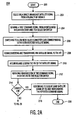
- FIG. 3 depicts a flow diagram of a method for providing feedback to an integrated receiver decoder (IRD) from a device coupled via a unidirectional signal path. Specifically, method 300 provides feedback to an IRD in an instance where a command signal from the IRD to a selector switch is degraded or incomplete.
- IRD integrated receiver decoder
- the method 300 starts at step 301, and proceeds to step 302 where the IRD sends a command signal to the selector switch to couple a low noise block converter LNB to the IRD to receive a satellite signal from a satellite network, as selected by a user.
- step 304 if the command signal is without degradation, then the method 300 proceeds to step 306.
- step 306 the method 300 proceeds to method 200, beginning at step 206 as depicted in FIG. 2 .
- step 304 the command signal is incomplete or degraded to the point that a microcontroller of the selector switch cannot determine which LNB is to be coupled to the IRD, then the method proceeds to step 308.
- step 308 the microcontroller terminates the satellite signal it is currently receiving. In this instance, the microcontroller deactivates or disconnects the active relay receiving the satellite signal.
- the satellite signal being broadcast from the satellite and received by the LNB is cut off at the selector switch, resulting in the IRD becoming unlocked from the satellite signal.
- step 310 the IRD begins to search for the lost satellite signal.
- the search by the IRD is performed by repeating the command signal it previously sent to the selector switch. Thereafter, the method 300 proceeds to step 312 where the method 300 returns to method 200, beginning at step 206 as depicted in FIG. 2 .
- the method provides feedback to the IRD whenever the command signal sent by the IRD is degraded beyond the microprocessor of the selector switch's ability to determine which LNB is required to satisfy the command signal sent by the IRD.
- the microprocessor terminates the currently received satellite signal, that act provides feedback to the IRD to let the IRD know that the command signal the IRD just sent was defective.
- the IRD will know that the selector switch did not respond to IRD's command, and a repeated command signal must be issued.
- a method inventively repeats the command signal sent to the selector switch to couple the IRD with an LNB corresponding to the broadcast channel selected by a user, thereby providing redundancy. Additionally, in another embodiment, a method provides feedback to the IRD from the selector switch to force the IRD to send a repeated command signal in an instance that a prior command signal sent by the IRD was defective.
Description
- The present invention relates to a Direct Broadcast Satellite (DBS) system. More particularly, the invention relates to a method and apparatus for selecting one of a plurality of information signals broadcast from at least one satellite in the Direct Broadcast Satellite (DBS) system.
- Direct Broadcast Satellite (DBS) content providers have chosen to use multiple satellite networks to distribute their signals. In the past, a Low Noise Block converter (LNB) supply voltage (+ 13V/+ 18V) has been used to select between the two polarities of signals that were available on a single satellite network. Additionally, if signals from only two satellites are available for reception, then the presence or absence of a 22 KHz tone superimposed on the LNB supply voltage may be used to switch between either of the two satellite networks.
- When the number of satellite networks grows beyond two, the voltage, and tone switching combination is no longer sufficient. One method to overcome this impediment is through bi-directional communications between an integrated receiver/decoder (IRD) and a satellite selector switch, such as used in the European standard known as DISEQ. The IRD sends a command signal to the selector switch to switch to a selected satellite network. The two-way (bi-directional) protocol provides an avenue for feedback from the switch to the IRD. Thus, in an instance where the IRD sends a command to the selector switch, the selector switch upon switching, sends an acknowledgement message back to the IRD.
- However, not all satellite systems utilize bi-directional protocols, rather many utilize unidirectional messaging. The problem encountered by an integrated receiver/decoder (IRD) using a unidirectional messaging system is that the IRD has no feedback from the switch. Thus, a message may be sent to the switch, nevertheless, the IRD has no way of knowing whether or not the switch actually received the message and then switched.
- The lack of feedback may cause a problem if the user disconnects and reconnects the transmission coaxial cable, for example, in an attempt to reset the IRD and switch. The IRD will search for the lost satellite signal throughout each of the satellite networks by attempting to send messages to the switch, even though the switch is not connected to the IRD. When the user reconnects the switch via the coaxial cable, the switch will default to the prior transponder, which is not necessarily the transponder the IRD was expecting to switch to. Thus, the user will receive the wrong satellite signal.
- Furthermore, the lack of feedback from the switch may cause a problem when the IRD sends a command signal that is degraded or incomplete (e.g., coaxial cable signal losses). In this instance, the switch may fail to properly select the correct transponder on a satellite or the correct satellite thereby sending the user an incorrect satellite signal.
- Therefore, it is desirable to provide a method and apparatus for ensuring proper satellite network and transponder selection via the IRD and switch. It is also desirable to provide a form of feedback from the switch to indicate that the switch has failed to properly select a desired satellite signal.
- The disadvantages heretofore associated with the prior art, are overcome by the present invention of a method and apparatus for selecting a specific satellite signal. Specifically, a user selects a satellite signal via an integrated receiver/decoder (IRD), from at least one satellite network. The IRD sends a command signal to a selector switch to switch to one of a plurality of low noise block converters (LNB) coupled to a satellite collector dish.
- The command signal is transmitted from the IRD whenever the integrated receiver/decoder has not locked on to the satellite signal. Once the IRD acquires the satellite signal, the IRD repeats the transmission of the command signal to the selector switch. Thus, in the event that the selector switch failed to switch to the LNB corresponding to the initial command signal, then the repeated command signal helps to ensure that the selector switch switches to the LNB corresponding with the latest command signal sent by the IRD.
- The teachings of the present invention can be readily understood by considering the following detailed description in conjunction with the accompanying drawings, in which:
-
FIG. 1 depicts a block diagram of a Direct Broadcast Satellite System; -
FIGS. 2A and2B depict a flow diagram of a method for selecting a broadcasted satellite signal from a satellite network; and -
FIG. 3 depicts a flow diagram of a method for providing feedback to an integrated receiver/decoder from a device coupled via a unidirectional signal path. -
FIG. 1 depicts a block diagram of a direct broadcastsatellite communications system 100. The direct broadcast satellite (DBS)system 100 comprises aservice provider 130 from which audio, video, and/or data may be (hereinafter "satellite signal") uplinked to a satellite network comprising at least onesatellite network 132. Eachsatellite network 132 includes asatellite 133 having a plurality of transponders for downlinking the satellite signal to a plurality ofsubscriber equipment 102 having satellite signal receiving capabilities.Subscriber equipment 102 for a single location is depicted inFIG. 1 . - Specifically, a DBS
service provider 130 provides hundreds of television channels including a program guide from which a subscriber may choose programming. The subscriber may select any channel via aninput device 103 such as a remote control, for tuning an integrated receiver/decoder (IRD) 104 to the carrier frequency of the selected satellite signal. The directbroadcast satellite system 100, in conjunction with a method of requesting a satellite signal by a subscriber, as will be described in more detail hereinafter, advantageously ensures that the correct satellite signal is selected and coupled to the IRD 104. - In particular, the
subscriber equipment 102 comprises the IRD 104 having aprocessor 106, atuner 107,memory 108, and adatalink 105. Thedatalink 105 is utilized in adigital IRD 104. In general, thetuner 107 tunes to a desired transponder frequency and down-converts that frequency to a baseband signal (e.g., approaching zero cycles/sec.) The baseband signals are sent to thedatalink 105 where the baseband signals are converted from an analog to digital data format. The digital data is then sent to thememory 107 andprocessor 106 for storage and further processing, respectfully. - The IRD 104 is coupled to a
selector switch 120, via asignal path 109 such as a coaxial cable or a common transmission line. Theselector switch 120 comprises acontroller 122 such as a microcontroller, and a plurality ofswitching devices 124 such as relays. Upon sending a subscriber request for information, theprocessor 106 of the IRD 104 sends a command signal (e.g., 22 kHz tone) via thecoaxial cable 109, to themicrocontroller 122 of theselector switch 120. - The
selector switch 120 is at coupled to at least onecollector dish 126, through 126m (collectively, collector dishes 126). Eachcollector dish 126 has at least one low noise block (LNB)converter 128, through 128p (collectively LNB 128) coupled to thecollector dish 126 via a feedhorn (not shown). For example, anelliptical collector dish 1 26 may have threeLNBs 128 coupled to a single feedhorn, wherein each LNB is capable of receiving signals from threedistinct satellite networks 132. - Specifically, each
relay 124 of theselector switch 1 20 is correspondingly coupled to at least one low noise block (LNB)converter 128 via at least one signal path 121, through 121p (collectively signal paths 121). Each low noise block converter (LNB) is capable of selectively receiving the radiated signals from one of thesatellite networks 132 and down-converting the satellite signal to an intermediate frequency (IF) signal. Thereafter, the IF signals travel via the signal path 121 , through theselector switch 120 and to theIRD 104. - Satellites radiate microwave signal beams in various bandwidths having a range of frequencies such as the C-band (i.e., 3.7 to 6.425 GHz) and Ku-band (i.e., 10.7 to 18.1 GHz). Satellite television signals are polarized. This property of the satellite signals is used to improve spectrum efficiency in the satellite frequency bands. Two different types of polarization (i.e., the orientation of the electric field distal from the antenna) have been employed in satellite television applications.
- Linear polarization has two alternate states, i.e., horizontal and vertical polarization (HP and VP). Similarly circular polarization has two alternate states, i.e., left hand, and right hand circular polarization (LHCP and RHCP). The
IRD 104 is capable of determining the type of polarization for the satellite signal selected by a user. TheIRD 104 then sends a 13 volt or 18 volt signal as part of the command signal to theLNB 128 to enable theLNB 1 28 to differentiate between the polarization states i.e., the LHCP and RHCP, or the HP and VP. - The
IRD 104 may send as the command signal a 22 KHz tone to theselector switch 120, where the presence or absence of the tone is used to switch between two satellites. In an instance where more than two satellite networks exist, the command signal will provide a message containing the orbital slot pertaining to the selected satellite. - Accordingly, when the
collector dish 126 receives the radiated signal from the satellite, theLNB 128 corresponding to the command signal sent by theIRD 104 is able to select and amplify the incoming polarized satellite signal to a level that can be demodulated by theIRD 104. Furthermore, theLNB 128 down-converts the incoming satellite signal to an intermediate frequency (IF), illustratively, from a 12 GHz range down to 1 to 2 GHz. The down-conversion is performed by theLNB 128 in order to minimize high cable loses, typically occurring at 4 and 12 GHz. - The
IRD 104 locks onto the selected satellite signal, and the selected satellite signal is down-converted to the specific frequency pertaining to the program channel selected by the user. Thereafter, the satellite signal is demodulated and decoded into the audio, video, and/or data signal components. The audio, video, and/or data signal components are then sent to asubscriber output device 108 such as a television set, recorder, computer, or other processing or recording device. -
FIGS. 2A and2B depict a flow diagram of a method for selecting a broadcasted satellite signal from a satellite network. Themethod 200 starts atstep 201 and proceeds to step 202 where a subscriber makes a request for information by selecting an information channel from their remote control device. - In
step 204, an integrated receiver/decoder (IRD) receives the subscriber request and a processor of the IRD sends a command signal, such as a 22 KHz pulse width modulation tone, over a coaxial cable coupled to a selector switch having a microcontroller. The microcontroller of the selector switch decodes the command signal from the IRD to identify a signal path required to receive the satellite signal selected by the user. - In
step 206, the microcontroller activates a relay in the selector switch to couple the IRD to a corresponding satellite signal collector dish having a low noise block converter (LNB). The corresponding LNB allows the collector dish to focus and downlink the radiated satellite signals from the service provider's satellite to the receiving elements of the selected LNB. - In
step 208, the selected satellite signal is down-converted by the LNB to an intermediate frequency and then transferred through the selector switch and coaxial cable to the IRD. Instep 210, the IRD acquires and locks on to the down-converted satellite signal and then themethod 200 proceeds to step 212. - In
step 212, the IRD repeats the transmission of the command signal to the selector switch. The repeated command signal is provided to ensure that the selector switch is not set to an LNB corresponding to a different transponder or satellite network carrying a satellite signal not requested by the IRD. - In
step 214, if the selector switch is correctly coupled to the appropriate LNB to receive the selected satellite signal during the initial command signal (i.e., step 204), then themethod 200 proceeds to step 216. Instep 216, the repeated command signal is disregarded without consequence and the IRD continues to receive the same satellite signal without interruption. Thus the subscriber will receive the requested satellite signal as per the initial command signal sent by the IRD, without interference from the repeated command signal. Themethod 200 then proceeds to step 230 and ends. - Conversely, the selector switch may appear to be set to the wrong LNB from the perspective of the IRD. Such situation may occur when the IRD has lost the locked satellite signal.
- When the satellite signal is lost, i.e., "unlocked", then the IRD sends out consecutive command signals to the selector switch in order to search for the lost satellite signal. The command signals are sent to the selector switch to switch amongst the LNBs until a satellite signal is received by the IRD. The unlocking of the satellite signal may occur due to noise in the system, such as degradation of the signal on the coaxial cable, or a disruption in the connection between the IRD and switch, illustratively caused by a user disconnecting the coaxial cable temporarily to reset the IRD and switch, or otherwise.
- For example, if a user has been viewing a selected broadcast satellite channel and then disconnects the coaxial cable, the IRD will stop receiving the locked satellite signal. The IRD will then begin searching for the lost signal from the service provider. The search is performed by the IRD across the satellite network, which may include switching the LNBs between satellites if more than one satellite network exists.
- Every time the IRD sends a command signal to the selector switch during the search, the IRD will assume the selector switch has switched according to the IRD's commands. However, the user, illustratively, has disconnected the coaxial cable in this instance, and therefore the IRD and selector switch are no longer coupled. Since the communications between IRD and switch is unidirectional, the IRD does not have any means to receive direct feedback from the selector switch after issuing a command signal. Therefore, the IRD mistakenly thinks the selector switch has responded to its commands, when in fact the selector switch has never received the command signals.
- When the user reconnects the coaxial cable, the IRD will acquire the satellite signal of which the IRD was originally tuned and locked upon via the LNB. Notwithstanding, the tuner of the IRD will be set to a different channel since the IRD has been searching throughout the satellite network for a signal. Thus, this newly acquired signal received by the IRD is deemed the wrong signal by the IRD.
- Therefore in
step 214, if the selector switch is not correctly coupled to the appropriate LNB to receive the selected DBS signal, then instep 218, the repeated command sent signal by the IRD to the selector switch changes the selector switch setting to the correct LNB. In particular, the selector switch then activates the relay coupled to the LNB corresponding to the last command signal the IRD sent out during its search for the satellite signal. When the selector switch switches to the (correct) LNB corresponding to the repeated (latest) IRD command signal, the previous (incorrect) satellite signal is unlocked from the IRD. - The
method 200 then proceeds to step 220, where the LNB receives, down-converts, and transfers the correct satellite signal to the IRD. Instep 222, the IRD again acquires and locks upon the incoming satellite signal. - Once the IRD locks onto the satellite signal, in
step 224, the processor of the IRD sends a repeated command signal to the selector switch. The repeated command signal is sent since, instep 218, the IRD had become unlocked from the previous satellite signal and thereafter performed a signal search. Then, instep 226, the repeated command signal ofstep 222 is ignored and the IRD continues to receive and lock onto the same satellite signal without consequence. - Henceforth, there is no further interaction between the IRD and the selector switch since the two devices have correctly selected the appropriate LNB to receive the selected satellite signal during the previous command signal in
steps 218 through 222. Thus the selector switch and LNB correlate with the command signal sent by the IRD. - In this manner, the
method 200 is designed to send a command signal whenever the tuner of an IRD is not locked onto a satellite signal. Furthermore, whenever the tuner of an IRD does lock onto a newly acquired satellite signal, a repeated command signal is sent to the selector switch to ensure that the selector switch has selected and coupled to the appropriate LNB. Themethod 200 then proceeds to step 230, where it ends until a user either selects another satellite channel or the IRD becomes unlocked from the satellite signal for some other reason such as discussed herein. - In an instance where there is degradation in the command signal sent by the IRD, then a second inventive method provides a means of feedback to the IRD to take specific recourse.
FIG. 3 depicts a flow diagram of a method for providing feedback to an integrated receiver decoder (IRD) from a device coupled via a unidirectional signal path. Specifically,method 300 provides feedback to an IRD in an instance where a command signal from the IRD to a selector switch is degraded or incomplete. - The
method 300 starts atstep 301, and proceeds to step 302 where the IRD sends a command signal to the selector switch to couple a low noise block converter LNB to the IRD to receive a satellite signal from a satellite network, as selected by a user. - In
step 304, if the command signal is without degradation, then themethod 300 proceeds to step 306. Instep 306, themethod 300 proceeds tomethod 200, beginning atstep 206 as depicted inFIG. 2 . - Alternatively, if, in
step 304, the command signal is incomplete or degraded to the point that a microcontroller of the selector switch cannot determine which LNB is to be coupled to the IRD, then the method proceeds to step 308. Instep 308, the microcontroller terminates the satellite signal it is currently receiving. In this instance, the microcontroller deactivates or disconnects the active relay receiving the satellite signal. Thus, the satellite signal being broadcast from the satellite and received by the LNB is cut off at the selector switch, resulting in the IRD becoming unlocked from the satellite signal. - In
step 310, the IRD begins to search for the lost satellite signal. The search by the IRD is performed by repeating the command signal it previously sent to the selector switch. Thereafter, themethod 300 proceeds to step 312 where themethod 300 returns tomethod 200, beginning atstep 206 as depicted inFIG. 2 . - In this manner, the method provides feedback to the IRD whenever the command signal sent by the IRD is degraded beyond the microprocessor of the selector switch's ability to determine which LNB is required to satisfy the command signal sent by the IRD. Thus, when the microprocessor terminates the currently received satellite signal, that act provides feedback to the IRD to let the IRD know that the command signal the IRD just sent was defective. Moreover, the IRD will know that the selector switch did not respond to IRD's command, and a repeated command signal must be issued.
- It should be apparent to those skilled in the art that a novel method for ensuring a correct satellite signal is being received by a tuner of an integrated receiver/decoder (IRD) has been provided. In one embodiment, a method inventively repeats the command signal sent to the selector switch to couple the IRD with an LNB corresponding to the broadcast channel selected by a user, thereby providing redundancy. Additionally, in another embodiment, a method provides feedback to the IRD from the selector switch to force the IRD to send a repeated command signal in an instance that a prior command signal sent by the IRD was defective.
- Although various embodiments that incorporate the teachings of the present invention have been shown and described in detail herein, those skilled in the art can readily devise many other varied embodiments that still incorporate these teachings.
Claims (5)
- Method for selecting a satellite signal using an integrated receiver/decoder (104) for receiving and decoding a satellite signal and a switch (120) for coupling a satellite signal to the integrated receiver/decoder (104), with respect to polarity, frequency band or LNB, the method including the steps ofa) selecting the satellite signal via the Integrated receiver/decoder (104);b) the integrated receiver/decoder (104) repeatedly sending a command signal to the switch (120) whenever the integrated receiver/decoder (104) has not locked onto an incoming satellite signal;c) the switch (120) switching to couple a satellite signal to the integrated receiver/decoder (104) in response to the command signal;d) the integrated receiver/decoder (104) acquiring and locking onto the incoming satellite signal;
characterised in that the method further includes the steps ofe) the integrated receiver/decoder (104) resending the command signal to the switch (120) once more after the integrated receiver/decoder (104) has acquired and locked onto the incoming satellite signal. - The method of claim 1, further including the steps off) the switch (120) comparing the resent command signal with the current switch setting;g) the switch (120) switching to couple the selected satellite signal to the integrated receiver/decoder (104) in response to the resent command signal upon determining that the current switch setting differs from the switch setting corresponding to the command signal;h) the switch (120) disregarding the resent command signal upon determining that the current switch setting already corresponds to the switch setting according to the command signal.
- The method of claim 1, wherein step d) includes the integrated receiver/decoder (104) acquiring and locking onto a non-selected satellite signal in the instance that the switch setting does not correspond to the switch setting according to the command signal.
- Integrated receiver/decoder (104) adapted to perform steps a), b), d), and e) according to the method of claim 1 or 3.
- Switch (120) adapted to perform steps c), f), g) and h) according to the method of claim 1 or 2.
Applications Claiming Priority (5)
| Application Number | Priority Date | Filing Date | Title |
|---|---|---|---|
| US14445699P | 1999-07-19 | 1999-07-19 | |
| US144456P | 1999-07-19 | ||
| US09/475,444 US6944878B1 (en) | 1999-07-19 | 1999-12-30 | Method and apparatus for selecting a satellite signal |
| US475444 | 1999-12-30 | ||
| PCT/US2000/017373 WO2001006687A1 (en) | 1999-07-19 | 2000-06-23 | Method and apparatus for selecting a satellite signal |
Publications (2)
| Publication Number | Publication Date |
|---|---|
| EP1197019A1 EP1197019A1 (en) | 2002-04-17 |
| EP1197019B1 true EP1197019B1 (en) | 2010-04-21 |
Family
ID=26842018
Family Applications (1)
| Application Number | Title | Priority Date | Filing Date |
|---|---|---|---|
| EP00944831A Expired - Lifetime EP1197019B1 (en) | 1999-07-19 | 2000-06-23 | Method and apparatus for selecting a satellite signal |
Country Status (11)
| Country | Link |
|---|---|
| US (1) | US6944878B1 (en) |
| EP (1) | EP1197019B1 (en) |
| JP (1) | JP4667688B2 (en) |
| KR (1) | KR100741332B1 (en) |
| CN (1) | CN1227845C (en) |
| AU (1) | AU770300B2 (en) |
| BR (1) | BRPI0012687B1 (en) |
| DE (1) | DE60044253D1 (en) |
| MX (1) | MXPA02000695A (en) |
| MY (1) | MY125253A (en) |
| WO (1) | WO2001006687A1 (en) |
Families Citing this family (30)
| Publication number | Priority date | Publication date | Assignee | Title |
|---|---|---|---|---|
| JP2002185880A (en) * | 2000-12-14 | 2002-06-28 | Sony Corp | Information processing unit and method, receiver and method, and recording medium |
| US7149470B1 (en) * | 2002-04-04 | 2006-12-12 | The Directv Group, Inc. | Direct broadcast receiver utilizing LNB in cascade |
| JP2004064731A (en) * | 2002-06-03 | 2004-02-26 | Sharp Corp | Low noise blocking-down converter |
| US7954127B2 (en) | 2002-09-25 | 2011-05-31 | The Directv Group, Inc. | Direct broadcast signal distribution methods |
| CN1926870B (en) | 2004-03-09 | 2010-08-25 | 汤姆逊许可证公司 | Verifying 22kHz tone operation in a set-top box |
| US7900230B2 (en) | 2005-04-01 | 2011-03-01 | The Directv Group, Inc. | Intelligent two-way switching network |
| US7945932B2 (en) | 2005-04-01 | 2011-05-17 | The Directv Group, Inc. | Narrow bandwidth signal delivery system |
| US7958531B2 (en) * | 2005-04-01 | 2011-06-07 | The Directv Group, Inc. | Automatic level control for incoming signals of different signal strengths |
| US7950038B2 (en) | 2005-04-01 | 2011-05-24 | The Directv Group, Inc. | Transponder tuning and mapping |
| US8024759B2 (en) * | 2005-04-01 | 2011-09-20 | The Directv Group, Inc. | Backwards-compatible frequency translation module for satellite video delivery |
| US8621525B2 (en) | 2005-04-01 | 2013-12-31 | The Directv Group, Inc. | Signal injection via power supply |
| US7987486B2 (en) | 2005-04-01 | 2011-07-26 | The Directv Group, Inc. | System architecture for control and signal distribution on coaxial cable |
| US8549565B2 (en) | 2005-04-01 | 2013-10-01 | The Directv Group, Inc. | Power balancing signal combiner |
| US8789115B2 (en) * | 2005-09-02 | 2014-07-22 | The Directv Group, Inc. | Frequency translation module discovery and configuration |
| US7937732B2 (en) | 2005-09-02 | 2011-05-03 | The Directv Group, Inc. | Network fraud prevention via registration and verification |
| US8422982B2 (en) * | 2005-10-03 | 2013-04-16 | Raven Nc Llc | Method and apparatus for DC power management within multi-channel LNBF |
| US8019275B2 (en) | 2005-10-12 | 2011-09-13 | The Directv Group, Inc. | Band upconverter approach to KA/KU signal distribution |
| US8515342B2 (en) * | 2005-10-12 | 2013-08-20 | The Directv Group, Inc. | Dynamic current sharing in KA/KU LNB design |
| US7991348B2 (en) | 2005-10-12 | 2011-08-02 | The Directv Group, Inc. | Triple band combining approach to satellite signal distribution |
| US8719875B2 (en) | 2006-11-06 | 2014-05-06 | The Directv Group, Inc. | Satellite television IP bitstream generator receiving unit |
| US8699983B2 (en) * | 2007-03-26 | 2014-04-15 | Thomson Licensing | Six port linear network single wire multi switch transceiver |
| US20080271092A1 (en) * | 2007-04-25 | 2008-10-30 | Kvh Industries, Inc. | Methods and apparatus for controlling a satellite antenna |
| TWI336591B (en) * | 2007-05-22 | 2011-01-21 | Mstar Semiconductor Inc | Digital video broadcasting-satellite multi-input receiving circuit and associated receving method thereof |
| US8712318B2 (en) | 2007-05-29 | 2014-04-29 | The Directv Group, Inc. | Integrated multi-sat LNB and frequency translation module |
| US8238813B1 (en) | 2007-08-20 | 2012-08-07 | The Directv Group, Inc. | Computationally efficient design for broadcast satellite single wire and/or direct demod interface |
| US9942618B2 (en) | 2007-10-31 | 2018-04-10 | The Directv Group, Inc. | SMATV headend using IP transport stream input and method for operating the same |
| US8229383B2 (en) | 2009-01-06 | 2012-07-24 | The Directv Group, Inc. | Frequency drift estimation for low cost outdoor unit frequency conversions and system diagnostics |
| JP5336598B2 (en) * | 2008-09-26 | 2013-11-06 | トムソン ライセンシング | Method for controlling signal transmission for multiple devices |
| US9681337B2 (en) * | 2015-08-05 | 2017-06-13 | Qualcomm Incorporated | Satellite-to-satellite handoff in satellite communications system |
| TWI572163B (en) * | 2015-08-07 | 2017-02-21 | 啟碁科技股份有限公司 | Switching device for satellite signals |
Family Cites Families (30)
| Publication number | Priority date | Publication date | Assignee | Title |
|---|---|---|---|---|
| JPS5861547U (en) * | 1981-10-19 | 1983-04-25 | デイエツクスアンテナ株式会社 | satellite receiver |
| JPS5915335A (en) * | 1982-07-15 | 1984-01-26 | Maspro Denkoh Corp | Satellite broadcast receiving device |
| US4876736A (en) * | 1987-09-23 | 1989-10-24 | A. C. Nielsen Company | Method and apparatus for determining channel reception of a receiver |
| KR910003234B1 (en) | 1988-05-18 | 1991-05-24 | 삼성전자 주식회사 | Low noise block converter for satellite communications |
| US4959873A (en) * | 1988-07-08 | 1990-09-25 | The Marconi Company Limited | Transmission line switch |
| US5099319A (en) * | 1989-10-23 | 1992-03-24 | Esch Arthur G | Video information delivery method and apparatus |
| KR940011752B1 (en) * | 1991-11-29 | 1994-12-23 | 삼성전기주식회사 | Lnb for satelite broadcasting receiver |
| US5303403A (en) * | 1992-06-16 | 1994-04-12 | Microelectronics Technology, Inc. | Electronic switch for selecting satellite polarization signals |
| US5388101A (en) | 1992-10-26 | 1995-02-07 | Eon Corporation | Interactive nationwide data service communication system for stationary and mobile battery operated subscriber units |
| US5424750A (en) | 1992-11-11 | 1995-06-13 | Dx Antenna Company, Limited | Stationary satellite signal receiving device |
| KR100291343B1 (en) * | 1993-10-25 | 2001-09-17 | 서평원 | Low noise block down converter |
| US5534941A (en) | 1994-05-20 | 1996-07-09 | Encore Media Corporation | System for dynamic real-time television channel expansion |
| US5708963A (en) | 1995-02-24 | 1998-01-13 | Scientific-Atlanta, Inc. | Method and apparatus for using satellites for reverse path communication in direct-to-home subscription information systems |
| US5550576A (en) | 1995-04-17 | 1996-08-27 | Starsight Telecast Incorporated | Method and apparatus for merging television program schedule information received from multiple television schedule information sources |
| US5828945A (en) | 1995-04-17 | 1998-10-27 | Starsight Telecast, Inc. | Merging multi-source information in a television system |
| KR0161946B1 (en) | 1995-11-03 | 1998-12-01 | 구자홍 | Setting detecting apparatus of satellite broadcasting antenna |
| JP3363022B2 (en) | 1996-03-07 | 2003-01-07 | ケイディーディーアイ株式会社 | Fixed earth station |
| KR980012706A (en) * | 1996-07-25 | 1998-04-30 | 김광호 | Broadcast confirmation and signal strength check device by repeater |
| GB2316832B (en) * | 1996-08-24 | 2001-05-16 | Ico Services Ltd | Signal assessed user terminal system access in satellite communication systems |
| US5886995A (en) | 1996-09-05 | 1999-03-23 | Hughes Electronics Corporation | Dynamic mapping of broadcast resources |
| JPH10145188A (en) | 1996-11-07 | 1998-05-29 | Sony Corp | Reception device |
| US6029044A (en) * | 1997-02-03 | 2000-02-22 | Hughes Electronics Corporation | Method and apparatus for in-line detection of satellite signal lock |
| US5940737A (en) * | 1997-02-27 | 1999-08-17 | Hughes Electronics Corporation | Signal selector |
| US5983071A (en) * | 1997-07-22 | 1999-11-09 | Hughes Electronics Corporation | Video receiver with automatic satellite antenna orientation |
| US5898455A (en) | 1997-12-23 | 1999-04-27 | California Amplifier, Inc. | Interface modules and methods for coupling combined communication signals to communication receivers |
| JP2002501343A (en) * | 1998-01-08 | 2002-01-15 | トムソン ライセンシング ソシエテ アノニム | Video program guide apparatus and method |
| DE29818825U1 (en) | 1998-02-12 | 1999-05-12 | Asc Tec Gmbh Antennen Satellit | Switching device for satellite reception |
| AU2395799A (en) * | 1998-05-07 | 1999-11-18 | Loral Spacecom Corp. | Two-way/broadcast mobile and portable satellite communications system |
| US6430165B1 (en) * | 1998-08-07 | 2002-08-06 | Hughes Electronics Corporation | Method and apparatus for performing satellite selection in a broadcast communication system |
| US6310661B1 (en) * | 1998-08-07 | 2001-10-30 | Hughes Electronics Corporation | Method of broadcasting controlling data streams and apparatus for receiving the same |
-
1999
- 1999-12-30 US US09/475,444 patent/US6944878B1/en not_active Expired - Lifetime
-
2000
- 2000-06-23 BR BRPI0012687A patent/BRPI0012687B1/en not_active IP Right Cessation
- 2000-06-23 JP JP2001511017A patent/JP4667688B2/en not_active Expired - Lifetime
- 2000-06-23 DE DE60044253T patent/DE60044253D1/en not_active Expired - Lifetime
- 2000-06-23 CN CNB00810574XA patent/CN1227845C/en not_active Expired - Lifetime
- 2000-06-23 MX MXPA02000695A patent/MXPA02000695A/en active IP Right Grant
- 2000-06-23 AU AU58866/00A patent/AU770300B2/en not_active Expired
- 2000-06-23 KR KR1020027000629A patent/KR100741332B1/en active IP Right Grant
- 2000-06-23 EP EP00944831A patent/EP1197019B1/en not_active Expired - Lifetime
- 2000-06-23 WO PCT/US2000/017373 patent/WO2001006687A1/en active IP Right Grant
- 2000-07-14 MY MYPI20003241 patent/MY125253A/en unknown
Also Published As
| Publication number | Publication date |
|---|---|
| MY125253A (en) | 2006-07-31 |
| BRPI0012687B1 (en) | 2016-03-29 |
| KR20020019530A (en) | 2002-03-12 |
| MXPA02000695A (en) | 2003-07-21 |
| EP1197019A1 (en) | 2002-04-17 |
| CN1361954A (en) | 2002-07-31 |
| WO2001006687A9 (en) | 2002-06-06 |
| AU770300B2 (en) | 2004-02-19 |
| JP2003505924A (en) | 2003-02-12 |
| WO2001006687A1 (en) | 2001-01-25 |
| CN1227845C (en) | 2005-11-16 |
| KR100741332B1 (en) | 2007-07-23 |
| DE60044253D1 (en) | 2010-06-02 |
| JP4667688B2 (en) | 2011-04-13 |
| AU5886600A (en) | 2001-02-05 |
| BR0012687A (en) | 2002-04-16 |
| US6944878B1 (en) | 2005-09-13 |
Similar Documents
| Publication | Publication Date | Title |
|---|---|---|
| EP1197019B1 (en) | Method and apparatus for selecting a satellite signal | |
| US5940737A (en) | Signal selector | |
| US7950038B2 (en) | Transponder tuning and mapping | |
| US8019275B2 (en) | Band upconverter approach to KA/KU signal distribution | |
| EP2081249A2 (en) | Power balancing signal combiner | |
| EP0595797A4 (en) | Method and system for receiving and distributing satellite transmitted television signals. | |
| US8689263B2 (en) | Backwards-compatible frequency translation module for satellite video delivery | |
| US9654838B2 (en) | Single-cable automatic IRD installation procedure | |
| US7245892B2 (en) | Satellite reception | |
| WO2006107869A2 (en) | Narrow bandwidth signal delivery system | |
| EP1878245A2 (en) | System architecture for control and signal distribution on coaxial cable | |
| JP4462719B2 (en) | CATV system headend | |
| JP2004248079A (en) | Television broadcast signaling system, transmitting device, and receiving device | |
| EP1177647A2 (en) | Direct to home satellite broadcasting system using a limited bandwidth channel | |
| JP3460474B2 (en) | NIT information acquisition method in CATV | |
| US20070288968A1 (en) | Video and data home networking architectures | |
| WO2007143219A9 (en) | Video and data home networking architectures | |
| JP2006332906A (en) | Catv system |
Legal Events
| Date | Code | Title | Description |
|---|---|---|---|
| PUAI | Public reference made under article 153(3) epc to a published international application that has entered the european phase |
Free format text: ORIGINAL CODE: 0009012 |
|
| 17P | Request for examination filed |
Effective date: 20020116 |
|
| AK | Designated contracting states |
Kind code of ref document: A1 Designated state(s): AT BE CH CY DE DK ES FI FR GB GR IE IT LI LU MC NL PT SE |
|
| AX | Request for extension of the european patent |
Free format text: AL;LT;LV;MK;RO;SI |
|
| RBV | Designated contracting states (corrected) |
Designated state(s): DE ES FR GB IT |
|
| 17Q | First examination report despatched |
Effective date: 20040721 |
|
| RAP1 | Party data changed (applicant data changed or rights of an application transferred) |
Owner name: THOMSON LICENSING |
|
| 17Q | First examination report despatched |
Effective date: 20040721 |
|
| GRAP | Despatch of communication of intention to grant a patent |
Free format text: ORIGINAL CODE: EPIDOSNIGR1 |
|
| RIC1 | Information provided on ipc code assigned before grant |
Ipc: H04N 5/00 20060101AFI20091102BHEP |
|
| RAP1 | Party data changed (applicant data changed or rights of an application transferred) |
Owner name: THOMSON LICENSING |
|
| GRAS | Grant fee paid |
Free format text: ORIGINAL CODE: EPIDOSNIGR3 |
|
| GRAA | (expected) grant |
Free format text: ORIGINAL CODE: 0009210 |
|
| AK | Designated contracting states |
Kind code of ref document: B1 Designated state(s): DE ES FR GB IT |
|
| REG | Reference to a national code |
Ref country code: GB Ref legal event code: FG4D |
|
| REF | Corresponds to: |
Ref document number: 60044253 Country of ref document: DE Date of ref document: 20100602 Kind code of ref document: P |
|
| REG | Reference to a national code |
Ref country code: GB Ref legal event code: 746 Effective date: 20100618 |
|
| PG25 | Lapsed in a contracting state [announced via postgrant information from national office to epo] |
Ref country code: ES Free format text: LAPSE BECAUSE OF FAILURE TO SUBMIT A TRANSLATION OF THE DESCRIPTION OR TO PAY THE FEE WITHIN THE PRESCRIBED TIME-LIMIT Effective date: 20100801 |
|
| PLBE | No opposition filed within time limit |
Free format text: ORIGINAL CODE: 0009261 |
|
| STAA | Information on the status of an ep patent application or granted ep patent |
Free format text: STATUS: NO OPPOSITION FILED WITHIN TIME LIMIT |
|
| 26N | No opposition filed |
Effective date: 20110124 |
|
| PG25 | Lapsed in a contracting state [announced via postgrant information from national office to epo] |
Ref country code: IT Free format text: LAPSE BECAUSE OF FAILURE TO SUBMIT A TRANSLATION OF THE DESCRIPTION OR TO PAY THE FEE WITHIN THE PRESCRIBED TIME-LIMIT Effective date: 20100421 |
|
| REG | Reference to a national code |
Ref country code: FR Ref legal event code: PLFP Year of fee payment: 17 |
|
| REG | Reference to a national code |
Ref country code: FR Ref legal event code: PLFP Year of fee payment: 18 |
|
| REG | Reference to a national code |
Ref country code: DE Ref legal event code: R082 Ref document number: 60044253 Country of ref document: DE Representative=s name: DEHNS, DE Ref country code: DE Ref legal event code: R082 Ref document number: 60044253 Country of ref document: DE Representative=s name: HOFSTETTER, SCHURACK & PARTNER PATENT- UND REC, DE |
|
| REG | Reference to a national code |
Ref country code: FR Ref legal event code: PLFP Year of fee payment: 19 |
|
| REG | Reference to a national code |
Ref country code: FR Ref legal event code: TP Owner name: THOMSON LICENSING DTV, FR Effective date: 20180830 |
|
| REG | Reference to a national code |
Ref country code: GB Ref legal event code: 732E Free format text: REGISTERED BETWEEN 20180927 AND 20181005 |
|
| REG | Reference to a national code |
Ref country code: DE Ref legal event code: R082 Ref document number: 60044253 Country of ref document: DE Representative=s name: DEHNS, DE Ref country code: DE Ref legal event code: R081 Ref document number: 60044253 Country of ref document: DE Owner name: INTERDIGITAL MADISON PATENT HOLDINGS, FR Free format text: FORMER OWNER: THOMSON LICENSING, ISSY-LES-MOULINEAUX, FR |
|
| PGFP | Annual fee paid to national office [announced via postgrant information from national office to epo] |
Ref country code: DE Payment date: 20190521 Year of fee payment: 20 |
|
| PGFP | Annual fee paid to national office [announced via postgrant information from national office to epo] |
Ref country code: FR Payment date: 20190522 Year of fee payment: 20 |
|
| PGFP | Annual fee paid to national office [announced via postgrant information from national office to epo] |
Ref country code: GB Payment date: 20190522 Year of fee payment: 20 |
|
| REG | Reference to a national code |
Ref country code: DE Ref legal event code: R071 Ref document number: 60044253 Country of ref document: DE |
|
| REG | Reference to a national code |
Ref country code: GB Ref legal event code: PE20 Expiry date: 20200622 |
|
| PG25 | Lapsed in a contracting state [announced via postgrant information from national office to epo] |
Ref country code: GB Free format text: LAPSE BECAUSE OF EXPIRATION OF PROTECTION Effective date: 20200622 |