EP1196930B2 - Sound-insulating device for an induction machine - Google Patents
Sound-insulating device for an induction machine Download PDFInfo
- Publication number
- EP1196930B2 EP1196930B2 EP00946655A EP00946655A EP1196930B2 EP 1196930 B2 EP1196930 B2 EP 1196930B2 EP 00946655 A EP00946655 A EP 00946655A EP 00946655 A EP00946655 A EP 00946655A EP 1196930 B2 EP1196930 B2 EP 1196930B2
- Authority
- EP
- European Patent Office
- Prior art keywords
- sound
- membrane
- insulating
- membrane portion
- tank
- Prior art date
- Legal status (The legal status is an assumption and is not a legal conclusion. Google has not performed a legal analysis and makes no representation as to the accuracy of the status listed.)
- Expired - Lifetime
Links
Images


Classifications
-
- H—ELECTRICITY
- H01—ELECTRIC ELEMENTS
- H01F—MAGNETS; INDUCTANCES; TRANSFORMERS; SELECTION OF MATERIALS FOR THEIR MAGNETIC PROPERTIES
- H01F27/00—Details of transformers or inductances, in general
- H01F27/33—Arrangements for noise damping
-
- H—ELECTRICITY
- H01—ELECTRIC ELEMENTS
- H01F—MAGNETS; INDUCTANCES; TRANSFORMERS; SELECTION OF MATERIALS FOR THEIR MAGNETIC PROPERTIES
- H01F27/00—Details of transformers or inductances, in general
- H01F27/28—Coils; Windings; Conductive connections
- H01F27/32—Insulating of coils, windings, or parts thereof
- H01F27/321—Insulating of coils, windings, or parts thereof using a fluid for insulating purposes only
Definitions
- the present invention relates to a sound-insulating device of the kind described in the preamble to the independent claim 1.
- the invention also relates to a liquid-insulated induction machine of the kind described in the preamble to the independent claim 12.
- induction machine means a stationary induction machine, that is, a transformer or an inductor. More particularly, the invention relates to a transformer or an inductor for voltage exceeding 1 kilovolt for a distribution or a transmission network.
- a liquid-insulated induction machine comprises a tank, filled with insulating fluid, in which an active part is placed.
- active part means an iron core and a winding subassembly. Due to electromagnetic forces, the active part oscillates during operation. These oscillations propagate in the insulating fluid to the roof, bottom and wall portions of the tank, which portions, outside the tank, generate an audible sound which may attain such sound intensities that it constitutes a problem. This is particularly the case for induction machines placed in densely populated areas.
- US patent No. 1,846,887 describes a sound-insulating device of the type described above, in which a hollow, gas-filled double wall with rigid spacing blocks is placed between the active part of a transformer and the tank thereof.
- the task of the double wall is to absorb oscillations generated by the active part and to prevent these oscillations from reaching the tank.
- the rigid spacing blocks limit the compressibility of the double wall and convey the oscillations from one side of the double wall to the other side thereof, whereby the oscillations easily pass through the double wall.
- the plate has a front wall, a side wall and a rear wall which define a gas-filled cavity.
- the front wall has a frame-shaped edge portion, extending along the major part of its circumference, the average wall thickness of the edge portion being considerably smaller than the average total wall thickness of the front wall. Admittedly, by the relatively thin edge portion, the plate exhibits a limited compressibility, but the rigid mid-portion of the front wall reduces the same and suppresses the sound-damping ability of the plate.
- the location of the plate directly on the inside of the tank causes vibrations to be easily transmitted from the plate to the tank.
- the object of the invention is to achieve a new type of sound-insulating device which is extremely compressible and which, at the same time, is simple in its construction, easy to manufacture and durable. This is achieved according to the invention by a sound-insulating device according to the features described in the characterizing portion of the independent claim 1.
- the object of the invention is to achieve an efficiently sound-damped stationary induction machine. This is achieved according to the invention by an induction machine according to the features described in the characterizing portion of the independent claim 12.
- an efficient sound insulation may be achieved by a sound-insulating device which, in contrast to known sound-insulating devices, is extremely compressible and resilient to all sound-generating oscillations occurring in the fluid, which sound-insulating device is placed between the active part and the tank, and spaced from the inside of the tank.
- the present invention aims to provide such a device.
- the sound-insulating device comprises a gas-filled cavity and a resilient membrane surrounding the cavity.
- the task of the membrane is to give the cavity a desired shape, to keep the cavity at the desired location in the induction machine, and to prevent the gas in the cavity from mixing with the insulating fluid.
- the membrane shall be as resilient as possible. In this context, it is very important for the gas not to leak out into the insulating fluid, since the insulating effect of the fluid in that case would be greatly deteriorated, which may result in damage to the induction machine.
- the sound-insulating device has an extent in one plane. In an induction machine, the sound-insulating device is arranged such that this plane substantially forms a right angle with the direction of propagation of the oscillations.
- the sound-insulated device thus has a first membrane portion which substantially faces the active part and a second membrane portion which is arranged in parallel with the first membrane portion and which substantially faces the inside of the tank.
- the membrane In its simplest and most resilient embodiment, the membrane consists of rubber or some other polymer material.
- An induction machine may, however, have a service life of more than 30 years. Therefore, from the point of view of strength, a membrane of thin sheet metal is preferable to a polymer membrane since the sound-insulating device must operate during the whole life of the induction machine without the gas in the cavity leaking out.
- the membrane is made from thin, stainless sheet steel, preferably of uniform thickness. From such a sheet, a membrane may be manufactured in a simple and rational way, which membrane is very resilient but which at the same time makes it possible to form the sound-insulating device into the desired shape.
- the sound-insulating device is made from two thin sheets which are pressed and which, along their edges, are gas-tightly attached to each other so as to surround the above-mentioned cavity.
- the sheets thereby form two membrane halves with an intermediate gas volume.
- a sound-insulating device mounted in an induction machine, filled with insulating fluid is influenced by the atmospheric pressure plus the hydrostatic pressure of the fluid, which gives an absolute pressure of about 100-200 kPa, depending on whether the sound-insulating device is placed at a high or a low level in the tank of the induction machine.
- the sound-insulating device must be able to withstand this pressure without the membrane being compressed to such an extent that opposite membrane portions are brought into rigid contact with one another, in which case the sound-insulating ability of the device would be greatly deteriorated.
- the pressure in the cavity is equal to or higher than the absolute pressure of the insulating fluid.
- a high pressure in the cavity suppresses the sound-insulating compressibility of the device, and preferably the pressure in the cavity shall be as low as possible without the opposite membrane portions being brought into rigid contact with one another.
- the pressure in the cavity is lower than the absolute pressure of the insulating fluid, and a resilient spacing member is arranged in the cavity making contact with the membrane at at least two points.
- the spacing member prevents rigid contact between opposite membrane portions, whereby a low pressure may be allowed in the cavity.
- At least one region of the membrane is folded or corrugated, whereby a membrane is obtained which withstands the pressure from the insulating fluid but which, at the same time, is resilient to oscillations in the fluid.
- folding may be easily achieved by pressing the sheet when manufacturing the sound-insulating device.
- the sound-insulating device is not placed in direct contact with the inside of the tank. Insulating fluid should occur between the sound-insulating device and the inside of the tank.
- the sound-insulating device is placed such that the shortest distance between the device and the active part is smaller than the shortest distance between the sound-insulating device and the inside of the tank.
- the sound-insulating device is placed as close to the active part as possible, whereby the liquid volume between the sound-damping plate and the inside of the tank is as large as possible.
- Figure 1 shows an example of a sound-insulating device, in the form of a circular sound-insulating plate.
- Figure 1 shows the plate in a section along the diameter of the plate.
- the plate comprises a gas-filled cavity 1 and a resilient membrane surrounding the cavity and consisting of a first membrane portion 2, at the top in the figure, and a second membrane portion 3, at the bottom in the figure.
- the membrane portion 2 has a part 4 which is folded along its circumference, in Figure 2 folded down, which part 4 terminates in a plane edge 5.
- the membrane portion 3 has a part 6 which is folded along its circumference, in Figure 2 folded up, which part 6 also terminates in a plane edge 7. At their edges 5 and 7, the membrane portions are gas-tightly attached to each other.
- a valve may be arranged in any of the membrane portions, through which valve gas is pumped into or out of the cavity 1, during manufacture of the plate, such that the desired pressure is obtained in the cavity, whereupon the valve is hermetically sealed, for example by being welded.
- the gas is preferably air, but also other gases may be used.
- the membrane portions 2 and 3 are preferably manufactured from thin, stainless sheet metal of uniform thickness, into which the folded parts 4 and 6 as well as the edges 5 and 7 are pressed.
- the plate shall operate in an induction machine for a long period of time. Since gas from a leaking plate may destroy the induction machine in which the plate is mounted, stainless sheet metal is a suitable material from the point of view of corrosion, especially considering the fact that the service life of an induction machine may be very long.
- a suitable wall thickness of the membrane is in the interval of 0.1-4 mm.
- a suitable diameter of the plate is in the interval of 250-550 mm and a suitable thickness of the plate is in the interval of 30-60 mm.
- Figures 2 and 3 show a plate with a membrane formed such that it is able to withstand the pressure of the insulating fluid but which, at the same time, is very resilient.
- Figure 3 shows the plate from above, and Figure 2 shows the plate in a section along the diameter of the plate, that is, along the line marked A-A in Figure 3 .
- the first membrane portion 2 has a plane region in the centre of the portion, and a folded or corrugated region 9 with ridges 10 and valleys 11 concentrically arranged around the centre of the membrane portion 2, the region 9 surrounding the plane region 8. Because of the folded region, the plane is extremely compressible in a direction orthogonally to the plane of the plate.
- the folded region 9 covers approximately half of the membrane portion 2. However, embodiments are possible wherein the folded region covers a larger or smaller part of the membrane portion than that which is shown in Figures 2 and 3 . In one embodiment, for example, the folded region may cover substantially the entire membrane.
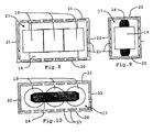
- FIG. 4 A second embodiment of the sound-insulating device is shown in Figure 4 in the form of a sound-insulating plate where also the second membrane portion 3 of the plate, the bottom one in the figure, is provided with a folded region 9. This arrangement further increases the compressibility of the plate.
- the pressure in the cavity is low.
- the cavity shall be almost evacuated of gas.
- a certain gas pressure must be allowed in the cavity to prevent the membrane portions 2 and 3 from being brought into rigid contact with each other.
- this arrangement entails a risk of gas leaking out into the insulating fluid of the induction machine. This may drastically deteriorate the insulating properties of the insulating fluid and lead to the occurrence of electrical flashovers which are devastating to the induction machine.
- FIG. 5 shows an embodiment of the sound-insulating device in the form of a sound-insulating plate, where a resilient spacing member in the form of five resilient rubber plates 12 are placed in the cavity 1.
- Figure 6 shows another embodiment in which a spacing member in the form of a spiral spring 13 is placed in the cavity 1
- Figure 7 shows a further embodiment in which a spacing member in the form of a resilient steel-wool cushion 14 is placed in the cavity 1.
- the sound insulating device shall be mounted between the active part and the tank.
- the sound-insulating device has an extent in one plane and preferably the sound-insulating device is arranged at right angles to the direction of propagation of the oscillations.
- Figures 8-10 show in three orthogonal views a transformer according to the invention, in which a plurality of sound-insulating plates of the type previously described with reference to Figures 2-7 , are mounted.
- the transformer comprises a tank filled with insulating fluid, in which tank an active part 17 with an iron core 18 and a winding subassembly 19 is placed.
- the inside of the tank has a floor portion 20, a roof portion 21 and a wall portion 22.
- a number of features such as bushings, connection leads to the winding subassemblies and other equipment normally occurring in a transformer are excluded from the figures for the sake of clarity.
- a plurality of sound-insulating plates 23 are mounted on stands (not shown). Each plate is aligned in such a way that one side of the plate substantially faces the active part, and the other side of the plate substantially faces the inside of the tank, that is, the floor portion 20, the roof portion 21 or the wall portion 22.
- Figures 11-13 show in three orthogonal views a preferred location of the sound-damping plates which, during experiments, have proved to provide a great sound-insulating effect.
- the plates 23 are placed closer to the active part than the inside of the tank 17 such that the shortest distance between each plate and the active part is smaller than the shortest distance between the plate and the inside of the tank 17.
- the plates 23 are preferably placed as close to the core 18 as possible.
Abstract
Description
- The present invention relates to a sound-insulating device of the kind described in the preamble to the
independent claim 1. The invention also relates to a liquid-insulated induction machine of the kind described in the preamble to theindependent claim 12. - In this patent application, induction machine means a stationary induction machine, that is, a transformer or an inductor. More particularly, the invention relates to a transformer or an inductor for voltage exceeding 1 kilovolt for a distribution or a transmission network.
- A liquid-insulated induction machine comprises a tank, filled with insulating fluid, in which an active part is placed. In this connection, active part means an iron core and a winding subassembly. Due to electromagnetic forces, the active part oscillates during operation. These oscillations propagate in the insulating fluid to the roof, bottom and wall portions of the tank, which portions, outside the tank, generate an audible sound which may attain such sound intensities that it constitutes a problem. This is particularly the case for induction machines placed in densely populated areas.
- It is known to reduce the above-mentioned sound by placing, between the active part and the tank, a sound-insulating device comprising a gas-filled cavity, for the purpose of preventing oscillations in the insulating fluid from reaching the floor, bottom or wall portions of the tank. However, known sound-insulating devices have a limited compressibility, which has proved to suppress the sound-damping effect.
-
US patent No. 1,846,887 describes a sound-insulating device of the type described above, in which a hollow, gas-filled double wall with rigid spacing blocks is placed between the active part of a transformer and the tank thereof. The task of the double wall is to absorb oscillations generated by the active part and to prevent these oscillations from reaching the tank. However, the rigid spacing blocks limit the compressibility of the double wall and convey the oscillations from one side of the double wall to the other side thereof, whereby the oscillations easily pass through the double wall. - Another sound-damping device of the type described above is described in
US patent No. 4,558,296 in the form of a sound-damping plate which is attached to the inside of a transformer tank. The plate has a front wall, a side wall and a rear wall which define a gas-filled cavity. The front wall has a frame-shaped edge portion, extending along the major part of its circumference, the average wall thickness of the edge portion being considerably smaller than the average total wall thickness of the front wall. Admittedly, by the relatively thin edge portion, the plate exhibits a limited compressibility, but the rigid mid-portion of the front wall reduces the same and suppresses the sound-damping ability of the plate. In addition, the location of the plate directly on the inside of the tank causes vibrations to be easily transmitted from the plate to the tank. - The object of the invention, from a first aspect of the invention, is to achieve a new type of sound-insulating device which is extremely compressible and which, at the same time, is simple in its construction, easy to manufacture and durable. This is achieved according to the invention by a sound-insulating device according to the features described in the characterizing portion of the
independent claim 1. - The object of the invention, from a second aspect of the invention, is to achieve an efficiently sound-damped stationary induction machine. This is achieved according to the invention by an induction machine according to the features described in the characterizing portion of the
independent claim 12. - Advantageous embodiments are described in the characterizing portions of the dependent claims.
- Experiments have shown that, in an induction machine with an active part, an insulating fluid surrounding the active part, and a tank enclosing the insulating fluid, an efficient sound insulation may be achieved by a sound-insulating device which, in contrast to known sound-insulating devices, is extremely compressible and resilient to all sound-generating oscillations occurring in the fluid, which sound-insulating device is placed between the active part and the tank, and spaced from the inside of the tank. The present invention aims to provide such a device.
- The sound-insulating device according to the invention comprises a gas-filled cavity and a resilient membrane surrounding the cavity. The task of the membrane is to give the cavity a desired shape, to keep the cavity at the desired location in the induction machine, and to prevent the gas in the cavity from mixing with the insulating fluid. Within the frameworks which these tasks mechanically impose on the membrane, the membrane shall be as resilient as possible. In this context, it is very important for the gas not to leak out into the insulating fluid, since the insulating effect of the fluid in that case would be greatly deteriorated, which may result in damage to the induction machine.
- The sound-insulating device has an extent in one plane. In an induction machine, the sound-insulating device is arranged such that this plane substantially forms a right angle with the direction of propagation of the oscillations. The sound-insulated device thus has a first membrane portion which substantially faces the active part and a second membrane portion which is arranged in parallel with the first membrane portion and which substantially faces the inside of the tank.
- In its simplest and most resilient embodiment, the membrane consists of rubber or some other polymer material. An induction machine may, however, have a service life of more than 30 years. Therefore, from the point of view of strength, a membrane of thin sheet metal is preferable to a polymer membrane since the sound-insulating device must operate during the whole life of the induction machine without the gas in the cavity leaking out. According to a preferred embodiment, the membrane is made from thin, stainless sheet steel, preferably of uniform thickness. From such a sheet, a membrane may be manufactured in a simple and rational way, which membrane is very resilient but which at the same time makes it possible to form the sound-insulating device into the desired shape. Preferably, the sound-insulating device is made from two thin sheets which are pressed and which, along their edges, are gas-tightly attached to each other so as to surround the above-mentioned cavity. The sheets thereby form two membrane halves with an intermediate gas volume.
- A sound-insulating device mounted in an induction machine, filled with insulating fluid, is influenced by the atmospheric pressure plus the hydrostatic pressure of the fluid, which gives an absolute pressure of about 100-200 kPa, depending on whether the sound-insulating device is placed at a high or a low level in the tank of the induction machine. The sound-insulating device must be able to withstand this pressure without the membrane being compressed to such an extent that opposite membrane portions are brought into rigid contact with one another, in which case the sound-insulating ability of the device would be greatly deteriorated.
- According to one embodiment of the sound-insulating device, the pressure in the cavity is equal to or higher than the absolute pressure of the insulating fluid. However, a high pressure in the cavity suppresses the sound-insulating compressibility of the device, and preferably the pressure in the cavity shall be as low as possible without the opposite membrane portions being brought into rigid contact with one another.
- According to another embodiment of the sound-insulating device, the pressure in the cavity is lower than the absolute pressure of the insulating fluid, and a resilient spacing member is arranged in the cavity making contact with the membrane at at least two points. The spacing member prevents rigid contact between opposite membrane portions, whereby a low pressure may be allowed in the cavity.
- According to the invention, at least one region of the membrane is folded or corrugated, whereby a membrane is obtained which withstands the pressure from the insulating fluid but which, at the same time, is resilient to oscillations in the fluid. In a membrane of thin sheet, folding may be easily achieved by pressing the sheet when manufacturing the sound-insulating device.
- To obtain a good sound-insulating effect, it is advantageous that the sound-insulating device is not placed in direct contact with the inside of the tank. Insulating fluid should occur between the sound-insulating device and the inside of the tank. Experiments have shown that it is advantageous to place the sound-damping device closer to the active part than the inside of the tank, and according to a preferred embodiment of the induction machine, the sound-insulating device is placed such that the shortest distance between the device and the active part is smaller than the shortest distance between the sound-insulating device and the inside of the tank. Preferably, the sound-insulating device is placed as close to the active part as possible, whereby the liquid volume between the sound-damping plate and the inside of the tank is as large as possible.
- The invention will be explained in greater detail in the following with reference to the accompanying drawings, wherein
- Figure 1
- shows an example of the sound-insulating device,
- Figures 2 and 3
- shows a first embodiment of the sound-insulating device according to the invention,
- Figure 4
- shows a second embodiment of the sound-insulating device according to the invention,
- Figure 5
- shows a third embodiment of the sound-insulating device according to the invention,
- Figure 6
- shows a fourth embodiment of the sound-insulating device according to the invention,
- Figure 7
- shows a fifth embodiment of the sound-insulating device according to the invention,
- Figures 8-10
- show in three orthogonal views a first embodiment of a transformer according to the invention, and
- Figures 11-13
- show in three orthogonal views a second embodiment of a transformer according to the invention.
-
Figure 1 shows an example of a sound-insulating device, in the form of a circular sound-insulating plate.Figure 1 shows the plate in a section along the diameter of the plate. The plate comprises a gas-filledcavity 1 and a resilient membrane surrounding the cavity and consisting of afirst membrane portion 2, at the top in the figure, and asecond membrane portion 3, at the bottom in the figure. Themembrane portion 2 has apart 4 which is folded along its circumference, inFigure 2 folded down, whichpart 4 terminates in aplane edge 5. In the same way, themembrane portion 3 has apart 6 which is folded along its circumference, inFigure 2 folded up, whichpart 6 also terminates in aplane edge 7. At theiredges cavity 1, during manufacture of the plate, such that the desired pressure is obtained in the cavity, whereupon the valve is hermetically sealed, for example by being welded. The gas is preferably air, but also other gases may be used. - The
membrane portions parts edges - Experiments have shown that a suitable wall thickness of the membrane is in the interval of 0.1-4 mm. A suitable diameter of the plate is in the interval of 250-550 mm and a suitable thickness of the plate is in the interval of 30-60 mm. By its construction with two membrane halves of thin, stainless sheet metal of uniform thickness, which are pressed and gas-tightly attached to each other, a sound-damping device is obtained which is simple and inexpensive to manufacture.
-
Figures 2 and 3 show a plate with a membrane formed such that it is able to withstand the pressure of the insulating fluid but which, at the same time, is very resilient.Figure 3 shows the plate from above, andFigure 2 shows the plate in a section along the diameter of the plate, that is, along the line marked A-A inFigure 3 . In this embodiment, thefirst membrane portion 2 has a plane region in the centre of the portion, and a folded orcorrugated region 9 withridges 10 andvalleys 11 concentrically arranged around the centre of themembrane portion 2, theregion 9 surrounding theplane region 8. Because of the folded region, the plane is extremely compressible in a direction orthogonally to the plane of the plate. InFigures 2 and 3 , the foldedregion 9 covers approximately half of themembrane portion 2. However, embodiments are possible wherein the folded region covers a larger or smaller part of the membrane portion than that which is shown inFigures 2 and 3 . In one embodiment, for example, the folded region may cover substantially the entire membrane. - A second embodiment of the sound-insulating device is shown in
Figure 4 in the form of a sound-insulating plate where also thesecond membrane portion 3 of the plate, the bottom one in the figure, is provided with a foldedregion 9. This arrangement further increases the compressibility of the plate. - As previously mentioned, it is advantageous if the pressure in the cavity is low. Preferably, the cavity shall be almost evacuated of gas. For the embodiments described with reference to
Figures 2-4 , a certain gas pressure must be allowed in the cavity to prevent themembrane portions - By arranging one or a plurality of resilient spacing members in the cavity, which at at least two points make contact with the membrane, a very low gas pressure may be allowed in the cavity since the spacing member prevents the
membrane portions Figure 5 shows an embodiment of the sound-insulating device in the form of a sound-insulating plate, where a resilient spacing member in the form of fiveresilient rubber plates 12 are placed in thecavity 1.Figure 6 shows another embodiment in which a spacing member in the form of aspiral spring 13 is placed in thecavity 1, andFigure 7 shows a further embodiment in which a spacing member in the form of a resilient steel-wool cushion 14 is placed in thecavity 1. By choosing spacing members and their dimensions, sound-insulating plates with different compressibility may be easily obtained. - To prevent oscillations in the insulating fluid from reaching the tank, the sound insulating device shall be mounted between the active part and the tank. Preferably, the sound-insulating device has an extent in one plane and preferably the sound-insulating device is arranged at right angles to the direction of propagation of the oscillations.
Figures 8-10 show in three orthogonal views a transformer according to the invention, in which a plurality of sound-insulating plates of the type previously described with reference toFigures 2-7 , are mounted. The transformer comprises a tank filled with insulating fluid, in which tank anactive part 17 with aniron core 18 and a windingsubassembly 19 is placed. The inside of the tank has afloor portion 20, aroof portion 21 and awall portion 22. A number of features such as bushings, connection leads to the winding subassemblies and other equipment normally occurring in a transformer are excluded from the figures for the sake of clarity. In the vicinity of the inside of the tank, but not in contact therewith, a plurality of sound-insulatingplates 23 are mounted on stands (not shown). Each plate is aligned in such a way that one side of the plate substantially faces the active part, and the other side of the plate substantially faces the inside of the tank, that is, thefloor portion 20, theroof portion 21 or thewall portion 22. -
Figures 11-13 show in three orthogonal views a preferred location of the sound-damping plates which, during experiments, have proved to provide a great sound-insulating effect. In this embodiment, theplates 23 are placed closer to the active part than the inside of thetank 17 such that the shortest distance between each plate and the active part is smaller than the shortest distance between the plate and the inside of thetank 17. In this arrangement, it is advantageous for each plate to be aligned in parallel with that of the surfaces of the core 18 which is closest to the plate. - The
plates 23 are preferably placed as close to the core 18 as possible. - The embodiments described above are to be regarded as examples since other embodiments may be achieved within the scope of the invention.
Claims (18)
- A stationary sound-insulating device for reducing the sound radiation from an induction machine with an active part, an insulating fluid surrounding the active part, and a tank enclosing the insulating fluid, wherein the soundinsulating device comprises a gas-filled cavity (1), wherein the sound-insulating device further comprises a resilient membrane (2,3) surrounding the gasfilled cavity (1), characterized in that
the device is extended in one plane and that the membrane has a first membrane portion (2) extending in the direction of the plane and a second membrane portion arranged substantially in parallel with the first membrane portion (2), wherein the device is in the form of a circular sound-insulating plate, wherein
any of the membrane portions (2,3) has at least one corrugated region (9), wherein the corrugated region with ridges and valleys is concentrically arranged around the centre of the membrane portion. - A sound-insulating device according to claim 1, characterized in that the corrugated region (9) covers at least one half of the membrane portion (2,3).
- A sound-insulating device according to claim 2, characterized in that the corrugated region (9) covers substantially the entire membrane portion (2,3).
- A sound-insulating device according to any of claims 1-3, characterized in that the pressure in the cavity (1) exceeds or is equal to the absolute pressure of the insulating fluid.
- A sound-insulating device according to any of claims 1-3, characterized in that the pressure in the cavity (1) is lower than the absolute pressure of the insulating fluid.
- A sound-insulating device according to any of the preceding claims, characterized in that a resilient spacing member is arranged in the cavity (1) making contact with the membrane (2,3) at at least two points.
- A sound-insulating device according claim 6, characterized in that the spacing member comprises a rubber plate (12).
- A sound-insulating device according claim 6, characterized in that the spacing member comprises a spiral spring (13).
- A sound-insulating device according claim 6, characterized in that the spacing member comprises a cushion of steel-wool (14).
- A sound-insulating device according to any of the preceding claims, characterized in that the membrane (2,3) has a substantially constant thickness.
- A sound-insulating device according to any of the preceding claims, characterized in that the membrane (2,3) is of thin, stainless sheet steel.
- A stationary induction machine with an active part (17) comprising a core (18) and a winding subassembly (19), an insulating fluid surrounding the active part, a tank (22) enclosing the insulating fluid, and at last one soundinsulating device (23) arranged in the insulating fluid between the active part and the tank, said device (23) comprising a gas-filled cavity (1), wherein the sound-insulating device (23) further comprises a resilient membrane (2,3) surrounding the cavity (1), the soundinsulating device being arranged spaced from the inside of the tank (22), characterized in that the device is extended in one plane and that the membrane has a first membrane portion (2) extending in the direction of the plane and a second membrane portion arranged substantially in parallel with the first membrane portion (2), wherein the device is in the form of a circular sound-insulating plate, wherein
any of the membrane portions (2,3) has at least one corrugated region (9), wherein the corrugated region with ridges and valleys is concentrically arranged around the centre of the membrane portion. - An induction machine according claim 12, characterized in that the sound-insulating device (23) is extended in one plane and is aligned substantially parallel to the inside of the tank (22), whereby the membrane has a first membrane portion (2) extending in the direction of the plane and facing the active part (17), and a second membrane portion (3) arranged substantially parallel to the first membrane portion and facing the inside of the tank (22).
- An induction machine according claim 12, characterized in that the sound-insulating device (23) is extended in one plane and is aligned substantially parallel to that of the surfaces of the core (18) which is closest to the plate, whereby the membrane has a first membrane portion (2) extending in the direction of the plane and facing the core (18) and a second membrane portion (3) arranged substantially parallel to the first membrane portion and facing the inside of the tank (22).
- An induction machine according to any of claims 13-14, characterized in that any of the membrane portions (2,3) has at least one corrugated region (9).
- An induction machine according to any of claims 12-15, characterized in that a resilient spacing member is arranged in the cavity (1) making contact with the membrane portion (2,3) at at least two points.
- An induction machine according to any of claims 12-16, characterized in that the membrane (1) has a substantially constant thickness.
- Use of an induction machine according to any of claims 13-17 in a distribution or transmission network.
Applications Claiming Priority (3)
| Application Number | Priority Date | Filing Date | Title |
|---|---|---|---|
| SE9902429 | 1999-06-28 | ||
| SE9902429A SE514509C2 (en) | 1999-06-28 | 1999-06-28 | stationary soundproofing device, stationary induction machine and use of such an induction machine |
| PCT/SE2000/001362 WO2001001425A1 (en) | 1999-06-28 | 2000-06-28 | Sound-insulating device for an induction machine |
Publications (3)
| Publication Number | Publication Date |
|---|---|
| EP1196930A1 EP1196930A1 (en) | 2002-04-17 |
| EP1196930B1 EP1196930B1 (en) | 2008-10-29 |
| EP1196930B2 true EP1196930B2 (en) | 2012-02-22 |
Family
ID=20416247
Family Applications (1)
| Application Number | Title | Priority Date | Filing Date |
|---|---|---|---|
| EP00946655A Expired - Lifetime EP1196930B2 (en) | 1999-06-28 | 2000-06-28 | Sound-insulating device for an induction machine |
Country Status (12)
| Country | Link |
|---|---|
| US (1) | US6661322B1 (en) |
| EP (1) | EP1196930B2 (en) |
| KR (1) | KR20020070774A (en) |
| CN (1) | CN1196149C (en) |
| AT (1) | ATE412968T1 (en) |
| AU (1) | AU6038000A (en) |
| BR (1) | BRPI0011786B1 (en) |
| CA (1) | CA2377967A1 (en) |
| DE (1) | DE60040669D1 (en) |
| RU (1) | RU2002101931A (en) |
| SE (1) | SE514509C2 (en) |
| WO (1) | WO2001001425A1 (en) |
Families Citing this family (12)
| Publication number | Priority date | Publication date | Assignee | Title |
|---|---|---|---|---|
| DE102004032952A1 (en) | 2004-07-07 | 2006-01-26 | Leica Microsystems Cms Gmbh | Scanning microscope and method for examining biological samples with a scanning microscope |
| MXNL05000025A (en) * | 2005-03-11 | 2006-09-11 | Prolec Ge S De R L De C V | Tank for electrical apparatus immersed in fluid. |
| US9607600B2 (en) | 2009-02-06 | 2017-03-28 | Sonobex Limited | Attenuators, arrangements of attenuators, acoustic barriers and methods for constructing acoustic barriers |
| FR2959859B1 (en) * | 2010-05-05 | 2013-06-28 | Areva T & D Sas | HIGH VOLTAGE OR MEDIUM VOLTAGE ELECTRICAL EQUIPMENT COMPRISING AN IMMERED INDUCTION ACTIVE PART WITH REDUCED NOISE |
| FR2959860B1 (en) | 2010-05-05 | 2013-06-28 | Areva T & D Sas | DEVICE FOR ACOUSTICALLY REDUCING WAVES ARISING FROM THE ACTIVE INDUCTION PORTION OF AN ELECTRICAL EQUIPMENT, WHILE HOLDING THE VACUUM VACUUM |
| DE102011006119A1 (en) * | 2011-03-25 | 2012-09-27 | Siemens Aktiengesellschaft | Transformer core and transformer |
| JP2014082397A (en) * | 2012-10-18 | 2014-05-08 | Toshiba Corp | Stationary induction electrical apparatus |
| GB201415873D0 (en) * | 2014-09-08 | 2014-10-22 | Sonobex Ltd | Apparatus And Method |
| EP3065129B1 (en) * | 2015-03-02 | 2018-10-03 | Siemens Aktiengesellschaft | Assembly for reducing the noise emissions of a transformer or a throttle |
| GB2548139B (en) * | 2016-03-10 | 2020-03-18 | General Electric Technology Gmbh | Improvements in or relating to sound reduction components for housings |
| CN108711496A (en) * | 2018-06-25 | 2018-10-26 | 河南森源电气股份有限公司 | A kind of oil-immersed type non-crystal alloy transformer |
| EP4235713A1 (en) | 2022-02-25 | 2023-08-30 | Hitachi Energy Switzerland AG | A transformer arrangement |
Citations (2)
| Publication number | Priority date | Publication date | Assignee | Title |
|---|---|---|---|---|
| US1846887A (en) † | 1930-05-24 | 1932-02-23 | Gen Electric | Electrical induction apparatus |
| GB925522A (en) † | 1958-12-17 | 1963-05-08 | Mc Graw Edison Co | Noise reducing means for transformers |
Family Cites Families (6)
| Publication number | Priority date | Publication date | Assignee | Title |
|---|---|---|---|---|
| US4228869A (en) * | 1976-07-17 | 1980-10-21 | Messerschmitt-Bolkow-Blohm Gmbh | Variable volume resonators using the Belleville spring principle |
| SE441317B (en) | 1984-02-14 | 1985-09-23 | Asea Ab | SOUND MUTING DEVICE |
| SE501456C2 (en) * | 1993-08-27 | 1995-02-20 | Gullfiber Ab | Wall arrangements |
| EP0819840A1 (en) * | 1996-07-17 | 1998-01-21 | Isuzu Ceramics Research Institute Co., Ltd. | A vibration and sound isolation device for a cogeneration system with an engine |
| US6401518B1 (en) * | 1999-07-29 | 2002-06-11 | General Electric Company | Fluid filled electrical device with diagnostic sensor located in fluid circulation flow path |
| US6424246B1 (en) * | 1999-12-02 | 2002-07-23 | Mcgraw-Edison Company | Transformer core and coil support |
-
1999
- 1999-06-28 SE SE9902429A patent/SE514509C2/en not_active IP Right Cessation
-
2000
- 2000-06-28 RU RU2002101931/09A patent/RU2002101931A/en not_active Application Discontinuation
- 2000-06-28 AT AT00946655T patent/ATE412968T1/en not_active IP Right Cessation
- 2000-06-28 AU AU60380/00A patent/AU6038000A/en not_active Abandoned
- 2000-06-28 EP EP00946655A patent/EP1196930B2/en not_active Expired - Lifetime
- 2000-06-28 BR BRPI0011786A patent/BRPI0011786B1/en not_active IP Right Cessation
- 2000-06-28 KR KR1020017016674A patent/KR20020070774A/en not_active Application Discontinuation
- 2000-06-28 WO PCT/SE2000/001362 patent/WO2001001425A1/en not_active Application Discontinuation
- 2000-06-28 CN CNB008122555A patent/CN1196149C/en not_active Expired - Lifetime
- 2000-06-28 CA CA002377967A patent/CA2377967A1/en not_active Abandoned
- 2000-06-28 US US09/926,837 patent/US6661322B1/en not_active Expired - Lifetime
- 2000-06-28 DE DE60040669T patent/DE60040669D1/en not_active Expired - Lifetime
Patent Citations (2)
| Publication number | Priority date | Publication date | Assignee | Title |
|---|---|---|---|---|
| US1846887A (en) † | 1930-05-24 | 1932-02-23 | Gen Electric | Electrical induction apparatus |
| GB925522A (en) † | 1958-12-17 | 1963-05-08 | Mc Graw Edison Co | Noise reducing means for transformers |
Also Published As
| Publication number | Publication date |
|---|---|
| WO2001001425A1 (en) | 2001-01-04 |
| EP1196930A1 (en) | 2002-04-17 |
| US6661322B1 (en) | 2003-12-09 |
| KR20020070774A (en) | 2002-09-11 |
| SE9902429L (en) | 2000-12-29 |
| CN1371520A (en) | 2002-09-25 |
| BR0011786A (en) | 2002-05-14 |
| RU2002101931A (en) | 2003-08-27 |
| CA2377967A1 (en) | 2001-01-04 |
| SE9902429D0 (en) | 1999-06-28 |
| ATE412968T1 (en) | 2008-11-15 |
| AU6038000A (en) | 2001-01-31 |
| DE60040669D1 (en) | 2008-12-11 |
| CN1196149C (en) | 2005-04-06 |
| EP1196930B1 (en) | 2008-10-29 |
| SE514509C2 (en) | 2001-03-05 |
| BRPI0011786B1 (en) | 2016-09-27 |
Similar Documents
| Publication | Publication Date | Title |
|---|---|---|
| EP1196930B2 (en) | Sound-insulating device for an induction machine | |
| EP2095381B1 (en) | Power transformer/reactor | |
| US5391835A (en) | Explosion resistant, oil insulated, current transformer | |
| US4558296A (en) | Sound damping devices | |
| US4055826A (en) | Resiliently supported windings in an electrical reactor | |
| JP2013183151A (en) | Stationary induction apparatus | |
| JP2013254881A (en) | Electrical apparatus | |
| US5184104A (en) | Electromagnetic induction apparatus with a sound suppressing arrangement | |
| US3175173A (en) | Shielded electrical induction apparatus | |
| EP0331008B1 (en) | Electromagnetic induction apparatus with a sound suppressing arrangement | |
| CN211344264U (en) | Casing with closed rib | |
| US5815059A (en) | Coaxial isolation mounting of a toroidal transformer | |
| KR20140037623A (en) | Trasformer tank | |
| JP3641114B2 (en) | Static induction machine | |
| WO2017199350A1 (en) | Transformer | |
| JP2016207856A (en) | Stationary induction conductor | |
| CN103559983A (en) | Low-noise SF6 gas insulated transformer and manufacturing method thereof | |
| JPH0541540Y2 (en) | ||
| JPS62241315A (en) | Sound-proof induction electric apparatus | |
| JP2004253623A (en) | Stationary equipment for electric power | |
| JPH09102421A (en) | Gas insulated induction device and tank for gas insulated induction device | |
| JPS59111310A (en) | Oil-immersed electric apparatus | |
| JPH07249529A (en) | Stationary induction electric apparatus | |
| JPH0612732B2 (en) | Induction tank | |
| JPH03120707A (en) | Static inductor |
Legal Events
| Date | Code | Title | Description |
|---|---|---|---|
| PUAI | Public reference made under article 153(3) epc to a published international application that has entered the european phase |
Free format text: ORIGINAL CODE: 0009012 |
|
| 17P | Request for examination filed |
Effective date: 20020128 |
|
| AK | Designated contracting states |
Kind code of ref document: A1 Designated state(s): AT BE CH CY DE DK ES FI FR GB GR IE IT LI LU MC NL PT SE |
|
| AX | Request for extension of the european patent |
Free format text: AL;LT;LV;MK;RO;SI |
|
| GRAP | Despatch of communication of intention to grant a patent |
Free format text: ORIGINAL CODE: EPIDOSNIGR1 |
|
| GRAS | Grant fee paid |
Free format text: ORIGINAL CODE: EPIDOSNIGR3 |
|
| GRAA | (expected) grant |
Free format text: ORIGINAL CODE: 0009210 |
|
| AK | Designated contracting states |
Kind code of ref document: B1 Designated state(s): AT BE CH CY DE DK ES FI FR GB GR IE IT LI LU MC NL PT SE |
|
| REG | Reference to a national code |
Ref country code: GB Ref legal event code: FG4D |
|
| REG | Reference to a national code |
Ref country code: CH Ref legal event code: EP |
|
| REG | Reference to a national code |
Ref country code: IE Ref legal event code: FG4D |
|
| REF | Corresponds to: |
Ref document number: 60040669 Country of ref document: DE Date of ref document: 20081211 Kind code of ref document: P |
|
| NLV1 | Nl: lapsed or annulled due to failure to fulfill the requirements of art. 29p and 29m of the patents act | ||
| PG25 | Lapsed in a contracting state [announced via postgrant information from national office to epo] |
Ref country code: ES Free format text: LAPSE BECAUSE OF FAILURE TO SUBMIT A TRANSLATION OF THE DESCRIPTION OR TO PAY THE FEE WITHIN THE PRESCRIBED TIME-LIMIT Effective date: 20090209 Ref country code: AT Free format text: LAPSE BECAUSE OF FAILURE TO SUBMIT A TRANSLATION OF THE DESCRIPTION OR TO PAY THE FEE WITHIN THE PRESCRIBED TIME-LIMIT Effective date: 20081029 |
|
| PG25 | Lapsed in a contracting state [announced via postgrant information from national office to epo] |
Ref country code: NL Free format text: LAPSE BECAUSE OF FAILURE TO SUBMIT A TRANSLATION OF THE DESCRIPTION OR TO PAY THE FEE WITHIN THE PRESCRIBED TIME-LIMIT Effective date: 20081029 Ref country code: FI Free format text: LAPSE BECAUSE OF FAILURE TO SUBMIT A TRANSLATION OF THE DESCRIPTION OR TO PAY THE FEE WITHIN THE PRESCRIBED TIME-LIMIT Effective date: 20081029 Ref country code: PT Free format text: LAPSE BECAUSE OF FAILURE TO SUBMIT A TRANSLATION OF THE DESCRIPTION OR TO PAY THE FEE WITHIN THE PRESCRIBED TIME-LIMIT Effective date: 20090330 |
|
| PLBI | Opposition filed |
Free format text: ORIGINAL CODE: 0009260 |
|
| PG25 | Lapsed in a contracting state [announced via postgrant information from national office to epo] |
Ref country code: BE Free format text: LAPSE BECAUSE OF FAILURE TO SUBMIT A TRANSLATION OF THE DESCRIPTION OR TO PAY THE FEE WITHIN THE PRESCRIBED TIME-LIMIT Effective date: 20081029 Ref country code: DK Free format text: LAPSE BECAUSE OF FAILURE TO SUBMIT A TRANSLATION OF THE DESCRIPTION OR TO PAY THE FEE WITHIN THE PRESCRIBED TIME-LIMIT Effective date: 20081029 |
|
| 26 | Opposition filed |
Opponent name: AREVA T&D SA Effective date: 20090715 |
|
| PLAX | Notice of opposition and request to file observation + time limit sent |
Free format text: ORIGINAL CODE: EPIDOSNOBS2 |
|
| PG25 | Lapsed in a contracting state [announced via postgrant information from national office to epo] |
Ref country code: SE Free format text: LAPSE BECAUSE OF FAILURE TO SUBMIT A TRANSLATION OF THE DESCRIPTION OR TO PAY THE FEE WITHIN THE PRESCRIBED TIME-LIMIT Effective date: 20090129 Ref country code: IT Free format text: LAPSE BECAUSE OF FAILURE TO SUBMIT A TRANSLATION OF THE DESCRIPTION OR TO PAY THE FEE WITHIN THE PRESCRIBED TIME-LIMIT Effective date: 20081029 |
|
| PG25 | Lapsed in a contracting state [announced via postgrant information from national office to epo] |
Ref country code: MC Free format text: LAPSE BECAUSE OF NON-PAYMENT OF DUE FEES Effective date: 20090630 |
|
| REG | Reference to a national code |
Ref country code: CH Ref legal event code: PL |
|
| PLBB | Reply of patent proprietor to notice(s) of opposition received |
Free format text: ORIGINAL CODE: EPIDOSNOBS3 |
|
| PG25 | Lapsed in a contracting state [announced via postgrant information from national office to epo] |
Ref country code: IE Free format text: LAPSE BECAUSE OF NON-PAYMENT OF DUE FEES Effective date: 20090628 Ref country code: LI Free format text: LAPSE BECAUSE OF NON-PAYMENT OF DUE FEES Effective date: 20090630 Ref country code: CH Free format text: LAPSE BECAUSE OF NON-PAYMENT OF DUE FEES Effective date: 20090630 |
|
| PG25 | Lapsed in a contracting state [announced via postgrant information from national office to epo] |
Ref country code: GR Free format text: LAPSE BECAUSE OF FAILURE TO SUBMIT A TRANSLATION OF THE DESCRIPTION OR TO PAY THE FEE WITHIN THE PRESCRIBED TIME-LIMIT Effective date: 20090130 |
|
| PG25 | Lapsed in a contracting state [announced via postgrant information from national office to epo] |
Ref country code: LU Free format text: LAPSE BECAUSE OF NON-PAYMENT OF DUE FEES Effective date: 20090628 |
|
| PG25 | Lapsed in a contracting state [announced via postgrant information from national office to epo] |
Ref country code: CY Free format text: LAPSE BECAUSE OF FAILURE TO SUBMIT A TRANSLATION OF THE DESCRIPTION OR TO PAY THE FEE WITHIN THE PRESCRIBED TIME-LIMIT Effective date: 20081029 |
|
| PUAH | Patent maintained in amended form |
Free format text: ORIGINAL CODE: 0009272 |
|
| STAA | Information on the status of an ep patent application or granted ep patent |
Free format text: STATUS: PATENT MAINTAINED AS AMENDED |
|
| 27A | Patent maintained in amended form |
Effective date: 20120222 |
|
| AK | Designated contracting states |
Kind code of ref document: B2 Designated state(s): AT BE CH CY DE DK ES FI FR GB GR IE IT LI LU MC NL PT SE |
|
| REG | Reference to a national code |
Ref country code: DE Ref legal event code: R102 Ref document number: 60040669 Country of ref document: DE Effective date: 20120222 |
|
| REG | Reference to a national code |
Ref country code: FR Ref legal event code: PLFP Year of fee payment: 17 |
|
| REG | Reference to a national code |
Ref country code: DE Ref legal event code: R082 Ref document number: 60040669 Country of ref document: DE Representative=s name: BECKER, KURIG, STRAUS, DE Ref country code: DE Ref legal event code: R082 Ref document number: 60040669 Country of ref document: DE Representative=s name: BECKER-KURIG-STRAUS PATENTANWAELTE PARTNERSCHA, DE Ref country code: DE Ref legal event code: R082 Ref document number: 60040669 Country of ref document: DE Representative=s name: BECKER & KURIG PARTNERSCHAFT PATENTANWAELTE MB, DE Ref country code: DE Ref legal event code: R082 Ref document number: 60040669 Country of ref document: DE Representative=s name: BECKER & KURIG PARTNERSCHAFT PATENTANWAELTE PA, DE Ref country code: DE Ref legal event code: R081 Ref document number: 60040669 Country of ref document: DE Owner name: ABB SCHWEIZ AG, CH Free format text: FORMER OWNER: ABB TECHNOLOGY AG, ZUERICH, CH |
|
| REG | Reference to a national code |
Ref country code: FR Ref legal event code: PLFP Year of fee payment: 18 |
|
| REG | Reference to a national code |
Ref country code: FR Ref legal event code: PLFP Year of fee payment: 19 |
|
| REG | Reference to a national code |
Ref country code: GB Ref legal event code: 732E Free format text: REGISTERED BETWEEN 20180719 AND 20180725 |
|
| REG | Reference to a national code |
Ref country code: FR Ref legal event code: CD Owner name: ABB SCHWEIZ AG, CH Effective date: 20181106 Ref country code: FR Ref legal event code: CD Owner name: ABB TRANSMISSION AND DISTRIBUTION MANAGEMENT L, CH Effective date: 20181106 Ref country code: FR Ref legal event code: TQ Owner name: ABB TRANSMISSION AND DISTRIBUTION MANAGEMENT L, CH Effective date: 20181106 Ref country code: FR Ref legal event code: TQ Owner name: ABB SCHWEIZ AG, CH Effective date: 20181106 |
|
| PGFP | Annual fee paid to national office [announced via postgrant information from national office to epo] |
Ref country code: FR Payment date: 20190628 Year of fee payment: 20 |
|
| PGFP | Annual fee paid to national office [announced via postgrant information from national office to epo] |
Ref country code: GB Payment date: 20190628 Year of fee payment: 20 Ref country code: DE Payment date: 20190628 Year of fee payment: 20 |
|
| REG | Reference to a national code |
Ref country code: DE Ref legal event code: R071 Ref document number: 60040669 Country of ref document: DE |
|
| REG | Reference to a national code |
Ref country code: GB Ref legal event code: PE20 Expiry date: 20200627 |
|
| PG25 | Lapsed in a contracting state [announced via postgrant information from national office to epo] |
Ref country code: GB Free format text: LAPSE BECAUSE OF EXPIRATION OF PROTECTION Effective date: 20200627 |