EP1195914A1 - Timing correcting device and timing correcting method - Google Patents
Timing correcting device and timing correcting method Download PDFInfo
- Publication number
- EP1195914A1 EP1195914A1 EP00940929A EP00940929A EP1195914A1 EP 1195914 A1 EP1195914 A1 EP 1195914A1 EP 00940929 A EP00940929 A EP 00940929A EP 00940929 A EP00940929 A EP 00940929A EP 1195914 A1 EP1195914 A1 EP 1195914A1
- Authority
- EP
- European Patent Office
- Prior art keywords
- path
- timing
- status
- tracking
- correcting device
- Prior art date
- Legal status (The legal status is an assumption and is not a legal conclusion. Google has not performed a legal analysis and makes no representation as to the accuracy of the status listed.)
- Granted
Links
Images


Classifications
-
- H—ELECTRICITY
- H04—ELECTRIC COMMUNICATION TECHNIQUE
- H04B—TRANSMISSION
- H04B1/00—Details of transmission systems, not covered by a single one of groups H04B3/00 - H04B13/00; Details of transmission systems not characterised by the medium used for transmission
- H04B1/69—Spread spectrum techniques
- H04B1/707—Spread spectrum techniques using direct sequence modulation
- H04B1/7097—Interference-related aspects
- H04B1/711—Interference-related aspects the interference being multi-path interference
- H04B1/7115—Constructive combining of multi-path signals, i.e. RAKE receivers
- H04B1/7117—Selection, re-selection, allocation or re-allocation of paths to fingers, e.g. timing offset control of allocated fingers
Definitions
- This invention relates to a timing correcting device within a mobile station accommodated in a mobile communication system that employs a CDMA (Code Division Multiple Access) system. Particularly, the invention relates to a timing correcting device within a mobile station and a timing correcting method for executing a timing control necessary for establishing a synchronization of CDMA communication signals.
- CDMA Code Division Multiple Access
- a reception timing of a receiving channel corresponding to a reception signal is detected by executing an inverse diffusion processing and a demodulation processing to pilot signals received in a predetermined period.
- reception signals are detected as a plurality of reception timing candidates in a RAKE path detector. In this case, paths detected as candidates have mutually different correlation values and reception timings.
- a main reception timing is determined from among the plurality of reception timing candidates. Specifically, at the mobile station, a reception reference timing held in advance is compared sequentially with the latest reception timing candidates. Then, the reception reference timing, that is, a clock to be managed inside, is corrected so that the reception reference timing coincides with an optimum reception timing that has been determined based on a result of the comparison.
- the optimum reception reference timing is obtained by absorbing a clock deviation between the mobile station and a base station, and a clock deviation due to a variation in a transmission distance, based on a clock correction.
- a timing correcting device for obtaining the optimum reception reference timing
- JP-A Japanese Patent Application Laid-open
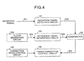
- Fig. 4 is a diagram showing a structure of a conventional timing correcting device described in the above publication.
- 101 denotes a reception timing detecting circuit
- 102 denotes a comparator circuit
- 103 denotes a reference timing generating circuit
- 104 denotes a clock generating circuit
- 105 denotes a timing correction control circuit
- 106 denotes a correction speed control circuit.
- the reception timing detecting circuit 101 generates a reception timing signal S(2) based on a pilot signal S(1) included in a reception signal, and outputs this to the comparator circuit 102.
- the reference timing generating circuit 103 generates a reference timing signal S(4) of a period that is substantially the same as the period of the reception timing signal S(2), based on a clock signal S(3) received from the clock generating circuit 104, and outputs this to the comparator circuit 102.
- the comparator circuit 102 compares the reception timing signal S(2) with the reference timing signal S(4), and outputs a result of this comparison to the timing correction control circuit 105 as a comparison result signal S(5).
- the reference timing generating circuit 103 corrects the reference timing signal S(4) so that this coincides with the reception timing signal S(2).
- a reception wave in a radio communication is transmitted as a "multi-path" consisting of a direct wave that arrives directly and a plurality of reflection waves that arrive after reflecting from buildings or the like.
- An amount of delay in a reflection wave from a direct wave is not constant, and this amount of delay changes dynamically as it is controlled by the surrounding buildings and the topography.
- a reception timing of a reception wave changes every moment due to a change in the propagation route according to a move.
- a direct wave is not always received, and sometimes the reception timing is detected from the reflection wave, and a reception reference timing is corrected by mistake in such a manner that it coincides with the reception timing of the reflection wave. Moreover, sometimes, at the next timing, a reception timing is detected from a direct wave, and a reception reference timing is corrected such that it coincides with the reception timing of the direct wave.
- the present invention has been made in the light of the above problems. It is an object of this invention to provide a method of and a device for correcting a timing that is capable of determining a reception reference timing efficiently and in optimum, by realizing a reduction in the load amount of correcting a reception reference timing and a reduction in the frequency of updating a path allocation.
- the timing correcting device relating to one aspect of the present invention comprises: a path detecting unit (corresponding to a RAKE path detecting circuit 1 in an embodiment to be described later) which detects a plurality of path candidates to be tracked from a reception signal, and outputting a "path timing" and a "detection correlation value" corresponding to each path candidate as a result; a plurality of decision reference generating units (corresponding to tracking-path candidate deciding circuits 2a, 2b, 2c, ...) that are individually allocated with a result of the detection, which generate a predetermined decision standard that is necessary for selecting an optimum path timing from among the timings of the path candidates, based on the allocated information; an optimum-path selecting unit (corresponding to a tracking-path selecting circuit 3) which selects an optimum path timing that should be tracked from among the timings of the path candidates, based on a result of the detection and the predetermined decision standard; a phase-difference calculating unit (corresponding to a comparator circuit 5) which compares a pre
- an optimum path around a reception reference timing is selected based on an output from each decision reference generating unit, and an internal clock is corrected based on a phase difference between the selected path and a predetermined reception reference timing.
- a center of a searcher and a finger window is always matched with the reception reference timing.
- the optimum-path selecting unit has a "path selection status", a "forward alignment status”, and a "tracking-path holding status” as statuses, wherein, during the "path selection status", the timing correcting device selects the optimum path timing from among the path candidates based on the detection correlation value or the predetermined decision standard, and thereafter shifts the status from the "path selection status" to the "tracking-path holding status", during the "tracking-path holding status", the timing correcting device compares a result of a detection of a latest path with a timing of a current optimum path thereby to decide whether a path updating processing is to be carried out or not, and carries out the updating processing when a path that satisfies a predetermined updating condition exists as a result of the comparison, and shifts the status from the "tracking-path holding status" to the "forward alignment status” when paths do not exist within a range of an error of a predetermined number of samples prescribed in advance, and during the "forward alignment status
- the optimum-path selecting unit it is possible to shift immediately to the "tracking-path holding status" by selecting an optimum path timing from timings of the output paths of each decision reference generating unit, without making a shift to the backward alignment status, even when the status has been shifted to the "path selection status", for example. Therefore, it is possible to substantially improve the operation speed relating to a timing correction.
- the timing correcting device makes each of the decision reference generating unit have a priority as the predetermined decision standard, and selects a timing of a path allocated to the decision reference generating unit having a highest priority as an optimum path timing.
- the optimum-path selecting unit which selects a timing of a path having a highest priority, it is possible to select a most stable path from among a plurality of path candidates.
- the timing correcting device utilizes the detection correlation value as one of the predetermined decision standards, and selects a timing of a path allocated to decision reference generating unit having a largest detection correlation value as an optimum path timing.
- the optimum-path selecting unit which selects a timing of a path having a largest detection correlation value, it is possible to select a most stable path from among a plurality of path candidates .
- the timing correcting device makes each of the decision reference generating unit have stability information of a detection correlation value as the predetermined decision standard, and selects a timing of a path allocated to decision reference generating unit having correlation value stability information of a smallest variation in correlation values, as an optimum path timing.
- the optimum-path selecting unit which selects a timing of a path having correlation value stability information of a smallest variation in correlation values, it is possible to select a most stable path from among a plurality of path candidates .
- timing correcting device of this invention when apath exists within a range of an error of a predetermined number of samples prescribed in advance as a result of a comparison in the "tracking-path holding status", this path satisfies the predetermined updating condition, and the timing correcting device updates the timing of this path as a next optimum path timing.
- timing correcting device of this invention when a plurality of paths exist within a range of an error of a predetermined number of samples prescribed in advance as a result of a comparison in the "tracking-path holding status", a path nearest to a current optimum path timing satisfies the predetermined updating condition, and the timing correcting device updates the timing of this path as a next optimum path timing.
- the timing correcting device of this invention when a plurality of paths exist within a range of an error of a predetermined number of samples prescribed in advance and further when two paths exist at both poles and at equal distance from a current optimum path timing as a result of a comparison in the "tracking-path holding status", a path having a higher detection correlation value satisfies the predetermined updating condition, and the timing correcting device updates the timing of this path as a next optimum path timing.
- the timing correcting device of this invention when a plurality of paths exist within a range of an error of a predetermined number of samples prescribed in advance and further when two paths exist at both poles and at equal distance from a current optimum path timing as a result of a comparison in the "tracking-path holding status", a path having a tracking polarity direction that is the same as a past tracking direction satisfies the predetermined updating condition, and the timing correcting device updates the timing of this path as a next optimum path timing.
- the decision reference generating unit has a "path selection status", a "backward alignment status”, a “forward alignment status”, and a “tracking-path holding status” as statuses, wherein, during the "path selection status", the timing correcting device outputs a timing of an allocated path based on a result of the detection, and thereafter shifts the status from the "path selection status" to the "backward alignment status", during the "backward alignment status", the timing correcting device compares a result of a latest path detection with a timing of a current output path, and shifts the status from the "backward alignment status" to the "path selection status” when paths do not exist within a range of an error of a predetermined number of samples prescribed in advance, and when a path exists within a range of an error of a predetermined number of samples prescribed in advance and further when paths exist continuously over and above a number of backward alignment stages, the timing correcting device shifts the status from the "backward alignment status" to the "tracking-path
- timing correcting device of this invention when a path exists within a range of an error of a predetermined number of samples prescribed in advance as a result of a comparison in the "tracking-path holding status", this path satisfies the predetermined updating condition, and the timing correcting device updates the timing of this path as a next output path timing.
- timing correcting device of this invention when a plurality of paths exist within a range of an error of a predetermined number of samples prescribed in advance as a result of a comparison in the "tracking-path holding status", a path nearest to a current output path timing satisfies the predetermined updating condition, and the timing correcting device updates the timing of this path as a next output path timing.
- the timing correcting device of this invention when a plurality of paths exist within a range of an error of a predetermined number of samples prescribed in advance and further when two paths exist at both poles and at equal distance from a current output path timing as a result of a comparison in the "tracking-path holding status", a path having a higher detection correlation value satisfies the predetermined updating condition, and the timing correcting device updates the timing of this path as a next output path timing.
- timing correcting device of this invention when a plurality of paths exist within a range of an error of a predetermined number of samples prescribed in advance and further when two paths exist at both poles and at equal distance from a current output path timing as a result of a comparison in the "tracking-path holding status", a path having a tracking polarity direction that is the same as a past tracking direction satisfies the predetermined updating condition, and the timing correcting device updates the timing of this path as a next output path timing.
- the timing correcting device calculates the stability information held by each decision reference generating unit by using the detection correlation value, a moving average of variation widths of the detection correlation value, an average of total past variation widths, a moving sum of variation widths, a moving average of detection correlation values, and/or a combination of these values.
- the optimum-path selecting unit can select a most stable path from among a plurality of path candidates. With this arrangement, it is also possible to substantially decrease the frequency of updating a path due to an erroneous tracking of a multi-path. As a result, it is possible to prevent a wasteful clock correction that has occurred in the past.
- the timing correcting method relating to another aspect of this invention comprises: a path detecting step of detecting a plurality of path candidates to be tracked from a reception signal; and outputting a "path timing" and a "detection correlation value" corresponding to each path candidate as a result; a decision reference generating step of individually allocating a result of the detection, and generating a predetermined decision standard that is necessary for selecting an optimum path timing from among the timings of the path candidates, based on the allocated information; an optimum-path selecting step of selecting an optimum path timing that should be tracked from among the timings of the path candidates, based on a result of the detection and the predetermined decision standard; a phase-difference calculating step of comparing a predetermined reception reference timing given from the outside with the optimum path timing, and calculating a phase difference between the two; and a timing correcting step of correcting the reception reference timing by controlling a clock based on the phase difference.
- an optimum path around a reception reference timing is selected based on an output at the decision reference generating step, and an internal clock is corrected based on a phase difference between the selected path and a predetermined reception reference timing.
- a center of a searcher and a finger window is always matched with the reception reference timing.
- the optimum-path selecting step has a "path selection status", a "forward alignment status”, and a "tracking-path holding status” as statuses, wherein, during the "path selection status", the optimum path timing is selected from among the path candidates based on the detection correlation value or the predetermined decision standard, and thereafter the status is shifted from the "path selection status" to the "tracking-path holding status", during the "tracking-path holding status", a result of a detection of a latest path is compared with a timing of a current optimum path thereby to decide whether a path updating processing is to be carried out or not, and the updating processing is carried out when a path exists that satisfies a predetermined updating condition as a result of the comparison, and the status is shifted from the "tracking-path holding status" to the "forward alignment status” when paths do not exist within a range of an error of a predetermined number of samples prescribed in advance, and during the "forward alignment status", a current optimum path
- the optimum-path selecting step it is possible to shift immediately to the "tracking-path holding status" by selecting an optimum path timing from timings of the output paths of each decision reference generating unit, without making a shift to the backward alignment status, even when the status has been shifted to the "path selection status", for example. Therefore, it is possible to substantially improve the operation speed relating to a timing correction.
- the decision reference generating step has a "path selection status", a "backward alignment status”, a “forward alignment status”, and a “tracking-path holding status” as statuses, wherein, during the "path selection status", a timing of an allocated path is output based on a result of the detection, and thereafter the status is shifted from the "path selection status" to the "backward alignment status", during the "backward alignment status", a result of a latest path detection is compared with a timing of a current output path, and the status is shifted from the "backward alignment status” to the "path selection status” when paths do not exist within a range of an error of a predetermined number of samples prescribed in advance, and when a path exists within a range of an error of a predetermined number of samples prescribed in advance and further when paths exist continuously over or above a number of backward alignment stages, the status is shifted from the "backward alignment status" to the "tracking-path holding status", during the "tracking-path holding
- Fig. 1 is a diagram showing a structure of the timing correcting device relating to the present invention.
- 1 denotes a RAKE path detecting circuit
- 2a, 2b, 2c, ... denote tracking-path candidate deciding circuits
- 3 denotes a tracking-path selecting circuit
- 4 denotes a reception reference counter
- 5 denotes a comparator circuit
- 6 denotes a timing correction control circuit
- 7 denotes a clock generating circuit.
- a reception base-band signal received by a mobile unit is input into the RAKE path detecting circuit 1.
- the RAKE path detecting circuit 1 detects a plurality of valid path candidates based on this reception signal. Thereafter, the RAKE path detecting circuit 1 outputs a "timing of each path" and a "detection correlation value" as a result of the RAKE path detection, to the tracking-path candidate deciding circuits 2a, 2b, 2c, ..., and the tracking-path selecting circuit 3.
- the RAKE detection is carried out in an over-sampling period of n (an integer) times.
- each tracking-path candidate deciding circuit generates and outputs a predetermined decision standard that is necessary for the tracking-path selecting circuit 3 to select an optimum path.
- the tracking-path selecting circuit 3 selects an optimum path to be tracked from among the detected paths, based on the result of the RAKE path detection and the predetermined decision standards.
- the "path timing" that is output from each tracking-path candidate deciding circuit as one of the predetermined decision standards will hereinafter be called a second main path timing.
- the tracking-path selecting circuit 3 selects an optimum path based on a result of the RAKE path detection. In the status other than the initial status, the tracking-path selecting circuit 3 selects an optimum path from among paths corresponding to the second main path timing, based on the predetermined decision standard
- the tracking-path selecting circuit 3 outputs the selected “path timing” as the “path timing” to be tracked, to the comparator circuit 5.
- the "path timing” that is output from the tracking-path selecting circuit as the path timing to be tracked will hereinafter be called a first main path timing.
- the comparator circuit 5 that has received the first main path timing compares a predetermined reception reference timing given from the outside and a reference counter value counted based on a clock signal from the clock generating circuit 7 with the first main path timing.
- a predetermined reception reference timing given from the outside and a reference counter value counted based on a clock signal from the clock generating circuit 7 with the first main path timing.
- an internal clock held by a mobile unit and an internal clock held by a base station do not operate completely in the same period, but have a constant clock deviation between them. This clock deviation may not be constant due to an influence of phasing or the like. Therefore, in order to receive accurately the information transmitted from the base station, it is necessary that this clock deviation is always corrected.
- the comparator circuit 5 checks whether there has been a deviation between the first main path timing and the reception reference timing set at the time of opening the reception channel, by carrying out the above comparison.
- the comparator circuit 5 carries out a comparison after standardizing the timing based on one channel.
- the timing correction control circuit 6 outputs a correction quantity corresponding to this phase difference to the clock generating circuit 7 at every constant period (period frame). For example, when there is a phase difference of a predetermined value (for example, 1/4 chip) or above between the reception reference timing and the first main path timing, the timing correction control circuit 6 generates a clock correction instruction to the clock generating circuit 7 at a rate of once per the above constant period frame. The clock generating circuit 7 corrects the counter value according to the posted correction quantity.
- a predetermined value for example, 1/4 chip
- an optimum path around the reception reference timing is selected based on the output from each tracking-path candidate deciding circuit.
- the internal clock is corrected based on a phase difference between the selected path and the predetermined reception reference timing.
- a center of a searcher and a finger window is always matched with the reception reference timing.
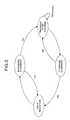
- Fig. 2 is a diagram showing a shift of a status of the tracking-path selecting circuit 3.
- the tracking-path selecting circuit 3 has a "path selection status", a "forward alignment status”, and a "tracking-path holding status" as statuses, for example.
- the tracking-path selecting circuit 3 selects a path having a largest detection correlation value as a path corresponding to the first main path timing from among the paths detected by the RKE path detecting circuit 1.
- the tracking-path selecting circuit 3 selects a path corresponding to the first main path timing from among the paths allocated as a plurality of second main path timings .
- the tracking-path selecting circuit 3 does not update the first main path timing. In the above operation, when a path corresponding to the first main path timing has been selected, the tracking-path selecting circuit 3 shifts the status from the "path selection status" to the "tracking-path holding status".
- the tracking-path selecting circuit 3 compares a result of the RAKE path detection with a current first main path timing, and decides whether an update processing is to be carried out or not. This will be explained in more detail.
- the tracking-path selecting circuit 3 in the "tracking-path holding status" shifts the status to the "forward alignment status".
- the tracking-path selecting circuit 3 in the "forward alignment status" holds the current tracking path as a path that corresponds to the first main path timing. In other words, the tracking-path selecting circuit 3 does not update the path.
- the tracking-path selecting circuit 3 shifts the status from the "forward alignment status" to the "path selection status".
- the tracking-path selecting circuit 3 because of the provision of the tracking-path selecting circuit 3, it is possible to shift immediately to the "tracking-path holding status"by selecting an optimum first main path timing from the second main path timings without making a shift to the backward alignment status, even when the status has been shifted to the "path selection status", for example. Therefore, it is possible to substantially improve the operation speed relating to a timing correction.
- Fig. 3 is a diagram showing a shift of a status of each tracking-path candidate deciding circuit.
- Each tracking-path candidate deciding circuit has, for example, a "path selection status", a "backward alignment status”, a “forward alignment status”, and a “tracking-path holding status” as statuses, and carries out a tracking operation to each different path.
- tracking-path candidate deciding circuits are allocated with m paths in the order of a large detection correlation value from among all paths that have been detected by the RAKE path detecting circuit 1.
- the m tracking-path candidate deciding circuits receive "path timings" and "detection correlation values” corresponding to respective paths. Then, each tracking-path candidate deciding circuit outputs a second main path timing corresponding to the allocated path, and shifts to the "backward alignment status".
- each tracking-path candidate deciding circuit compares a result of the RAKE path detection with a current second main path timing. When paths do not exist within a range of an error of a predetermined number of samples prescribed in advance, the tracking-path candidate deciding circuit shifts the status from the "backward alignment status" to the "path selection status". On the other hand, when paths exist within a range of an error of a predetermined number of samples prescribed in advance and further when paths exist continuously over and above a number of backward alignment stages, the tracking-path candidate deciding circuit shifts the status from the "backward alignment status" to the "tracking-path holding status".
- each tracking-path candidate deciding circuit compares a result of the RAKE path detection with a current second main path timing, and decides whether the update processing is to be carried out or not. This will be explained in more detail.
- each tracking-path candidate deciding circuit holds stability information of a detection correlation value.
- the stability of a detection correlation value is calculated form a variation width of the detection correlation value. It is also possible to calculate the stability based on a moving average of variation widths of the detection correlation value, an average of total past variation widths, a moving sum of variation widths, a moving average of detection correlation values, and/or a combination of these values.
- the tracking-path candidate deciding circuit in the "tracking-path holding status” shifts the status to the "forward alignment status".
- each tracking-path candidate deciding circuit holds a current tracking path as a second main path timing. In other words, the tracking-path candidate deciding circuit does not update the path.
- the tracking-path candidate deciding circuit shifts the status from the "forward alignment status" to the "path selection status".
- the tracking-path candidate deciding circuit 3 select a most stable path from among a plurality of path candidates. With this arrangement, it is possible to substantially decrease the frequency of updating a path due to an erroneous tracking of a multi-path. As a result, it is possible to prevent a wasteful clock correction that has occurred in the past.
- the timing correcting device and the timing correcting method relating to the present invention are useful for a mobile communication system that employs the CDMA system.
- the timing correcting device and the timing correcting method are suitable for a mobile station accommodated in the mobile communication system, that is, a demodulator of a portable telephone that requires a synchronous control within the mobile communication system.
Landscapes
- Engineering & Computer Science (AREA)
- Computer Networks & Wireless Communication (AREA)
- Signal Processing (AREA)
- Synchronisation In Digital Transmission Systems (AREA)
- Mobile Radio Communication Systems (AREA)
Abstract
Description
Claims (18)
- A timing correcting device comprising:a path detecting unit which detects a plurality of path candidates to be tracked from a reception signal, and outputting a "path timing" and a "detection correlation value" corresponding to each path candidate as a result;a plurality of decision reference generating units that are individually allocated with a result of the detection, which generate a predetermined decision standard that is necessary for selecting an optimum path timing from among the timings of the path candidates, based on the allocated information;an optimum-path selecting unit which selects an optimum path timing that should be tracked from among the timings of the path candidates, based on a result of the detection and the predetermined decision standard;a phase-difference calculating unit which compares a predetermined reception reference timing given from the outside with the optimum path timing, and calculates a phase difference between the two timings; anda timing correcting unit which corrects the reception reference timing by controlling a clock based on the phase difference.
- The timing correcting device according to claim 1, wherein
the optimum-path selecting unit has a "path selection status", a "forward alignment status", and a "tracking-path holding status" as statuses,
during the "path selection status", the timing correcting device selects the optimum path timing from among the path candidates based on the detection correlation value or the predetermined decision standard, and thereafter shifts the status from the "path selection status" to the "tracking-path holding status",
during the "tracking-path holding status", the timing correcting device compares a result of a detection of a latest path with a timing of a current optimum path thereby to decide whether a path updating processing is to be carried out or not, and carries out the updating processing when a path that satisfies a predetermined updating condition exists as a result of the comparison, and shifts the status from the "tracking-path holding status" to the "forward alignment status" when paths do not exist within a range of an error of a predetermined number of samples prescribed in advance, and
during the "forward alignment status", the timing correcting device holds a current optimum path timing when a path exists within a number of forward alignment stages even when paths do not exist within the range of an error of a predetermined number of samples prescribed in advance, and the timing correcting device shifts the status from the "forward alignment status" to the "path selection status" when no continuous paths exist over or above a number of forward alignment stages. - The timing correcting device according to claim 2, wherein
during the "path selection status", the timing correcting device makes each decision reference generating unit has a priority as the predetermined decision standard, and selects a timing of a path allocated to the decision reference generating unit having a highest priority as an optimum path timing. - The timing correcting device according to claim 2, wherein
during the "path selection status", the timing correcting device utilizes the detection correlation value as one of the predetermined decision standards, and selects a timing of a path allocated to the decision reference generating unit having a largest detection correlation value as an optimum path timing. - The timing correcting device according to claim 2, wherein
during the "path selection status", the timing correcting device makes each of the decision reference generating unit has stability information of a detection correlation value as the predetermined decision standard, and selects a timing of a path allocated to the decision reference generating unit having correlation value stability information of a smallest variation in correlation values, as an optimum path timing. - The timing correcting device according to claim 2, wherein
when a path exists within a range of an error of a predetermined number of samples prescribed in advance as a result of a comparison in the "tracking-path holding status", this path satisfies the predetermined updating condition, and the timing correcting device updates the timing of this path as a next optimum path timing. - The timing correcting device according to claim 2, wherein
when a plurality of paths exist within a range of an error of a predetermined number of samples prescribed in advance as a result of a comparison in the "tracking-path holding status", a path nearest to a current optimum path timing satisfies the predetermined updating condition, and the timing correcting device updates the timing of this path as a next optimum path timing. - The timing correcting device according to claim 2, wherein
when a plurality of paths exist within a range of an error of a predetermined number of samples prescribed in advance and further when two paths exist at both poles and at equal distance from a current optimum path timing as a result of a comparison in the "tracking-path holding status", a path having a higher detection correlation value satisfies the predetermined updating condition, and the timing correcting device updates the timing of this path as a next optimum path timing. - The timing correcting device according to claim 2, wherein
when a plurality of paths exist within a range of an error of a predetermined number of samples prescribed in advance and further when two paths exist at both poles and at equal distance from a current optimum path timing as a result of a comparison in the "tracking-path holding status", a path having a tracking polarity direction that is the same as a past tracking direction satisfies the predetermined updating condition, and the timing correcting device updates the timing of this path as a next optimum path timing. - The timing correcting device according to claim 2, wherein
each decision reference generating unit has a "path selection status", a "backward alignment status", a"forward alignment status", and a "tracking-path holding status" as statuses,
during the "path selection status", the timing correcting device outputs a timing of an allocated path based on a result of the detection, and thereafter shifts the status from the "path selection status" to the "backward alignment status",
during the "backward alignment status", the timing correcting device compares a result of a latest path detection with a timing of a current output path, and shifts the status from the "backward alignment status" to the "path selection status" when paths do not exist within a range of an error of a predetermined number of samples prescribed in advance, and when a path exists within a range of an error of a predetermined number of samples prescribed in advance and further when paths exist continuously over and above a number of backward alignment stages, the timing correcting device shifts the status from the "backward alignment status" to the "tracking-path holding status",
during the "tracking-path holding status", the timing correcting device compares a result of a detection of a latest path with a timing of a current output path thereby to decide whether a path updating processing is to be carried out or not, and carries out the updating processing when a path exists that satisfies a predetermined updating condition as a result of the comparison, and the timing correcting device shifts the status from the "tracking-path holding status" to the "forward alignment status" when paths do not exist within a range of an error of a predetermined number of samples prescribed in advance, and
during the "forward alignment status", the timing correcting device holds a current optimum path timing when a path exists within a number of forward alignment stages even when paths do not exist within the range of an error of a predetermined number of samples prescribed in advance, and the timing correcting device shifts the status from the "forward alignment status" to the "path selection status" when no continuous paths exist over or above a number of forward alignment stages. - The timing correcting device according to claim 10, wherein
when a path exists within a range of an error of a predetermined number of samples prescribed in advance as a result of a comparison in the "tracking-path holding status", this path satisfies the predetermined updating condition, and the timing correcting device updates the timing of this path as a next output path timing. - The timing correcting device according to claim 10, wherein
when a plurality of paths exist within a range of an error of a predetermined number of samples prescribed in advance as a result of a comparison in the "tracking-path holding status", a path nearest to a current output path timing satisfies the predetermined updating condition, and the timing correcting device updates the timing of this path as a next output path timing. - The timing correcting device according to claim 10, wherein
when a plurality of paths exist within a range of an error of a predetermined number of samples prescribed in advance and further when two paths exist at both poles and at equal distance from a current output path timing as a result of a comparison in the "tracking-path holding status", a path having a higher detection correlation value satisfies the predetermined updating condition, and the timing correcting device updates the timing of this path as a next output path timing. - The timing correcting device according to claim 10, wherein
when a plurality of paths exist within a range of an error of a predetermined number of samples prescribed in advance and further when two paths exist at both poles and at equal distance from a current output path timing as a result of a comparison in the "tracking-path holding status", a path having a tracking polarity direction that is the same as a past tracking direction satisfies the predetermined updating condition, and the timing correcting device updates the timing of this path as a next output path timing. - The timing correcting device according to claim 5, wherein
the timing correcting device calculates the stability information held by each decision reference generating unit by using the detection correlation value, a moving average of variation widths of the detection correlation value, an average of total past variation widths, a moving sum of variation widths, a moving average of detection correlation values, and/or a combination of these values. - A timing correcting method comprising:a path detecting step of detecting a plurality of path candidates to be tracked from a reception signal, and outputting a "path timing" and a "detection correlation value" corresponding to each path candidate as a result;a decision reference generating step of individually allocating a result of the detection, and generating a predetermined decision standard that is necessary for selecting an optimum path timing from among the timings of the path candidates, based on the allocated information;an optimum-path selecting step of selecting an optimum path timing that should be tracked from among the timings of the path candidates, based on a result of the detection and the predetermined decision standard;a phase-difference calculating step of comparing a predetermined reception reference timing given from the outside with the optimum path timing, and calculating a phase difference between the two; anda timing correcting step of correcting the reception reference timing by controlling a clock based on the phase difference.
- The timing correcting method according to claim 16, wherein
the optimum-path selecting step has a "path selection status", a "forward alignment status", and a "tracking-path holding status" as statuses,
during the "path selection status", the optimum path timing is selected from among the path candidates based on the detection correlation value or the predetermined decision standard, and thereafter the status is shifted from the "path selection status" to the "tracking-path holding status",
during the "tracking-path holding status", a result of a detection of a latest path is compared with a timing of a current optimum path thereby to decide whether a path updating processing is to be carried out or not, and the updating processing is carried out when a path exists that satisfies a predetermined updating condition as a result of the comparison, and the status is shifted from the "tracking-path holding status" to the "forward alignment status" when paths do not exist within a range of an error of a predetermined number of samples prescribed in advance, and
during the "forward alignment status", a current optimum path timing is held when a path exists within a number of forward alignment stages even when paths do not exist within the range of an error of a predetermined number of samples prescribed in advance, and the status is shifted from the "forward alignment status" to the "path selection status" when no continuous paths exist over or above a number of forward alignment stages. - The timing correcting method according to claim 17, wherein
the decision reference generating step has a "path selection status", a "backward alignment status", a "forward alignment status", and a "tracking-path holding status" as statuses,
during the "path selection status", a timing of an allocated path is output based on a result of the detection, and thereafter the status is shifted from the "path selection status" to the "backward alignment status",
during the "backward alignment status", a result of a latest path detection is compared with a timing of a current output path, and the status is shifted from the "backward alignment status" to the "path selection status" when paths do not exist within a range of an error of a predetermined number of samples prescribed in advance, and when a path exists within a range of an error of a predetermined number of samples prescribed in advance and further when paths exist continuously over or above a number of backward alignment stages, the status is shifted from the "backward alignment status" to the "tracking-path holding status",
during the "tracking-path holding status", a result of a detection of a latest path is compared with a timing of a current output path thereby to decide whether a path updating processing is to be carried out or not, and the updating processing is carried out when a path exists that satisfies a predetermined updating condition as a result of the comparison, and the status is shifted from the "tracking-path holding status" to the "forward alignment status" when paths do not exist within a range of an error of a predetermined number of samples prescribed in advance, and
during the "forward alignment status", a current optimum path timing is held when a path exists within a number of forward alignment stages even when paths do not exist within the range of an error of a predetermined number of samples prescribed in advance, and the status is shifted from the "forward alignment status" to the "path selection status" when no continuous paths exist over or above a number of forward alignment stages.
Applications Claiming Priority (1)
| Application Number | Priority Date | Filing Date | Title |
|---|---|---|---|
| PCT/JP2000/004408 WO2002003562A1 (en) | 2000-07-03 | 2000-07-03 | Timing correcting device and timing correcting method |
Publications (3)
| Publication Number | Publication Date |
|---|---|
| EP1195914A1 true EP1195914A1 (en) | 2002-04-10 |
| EP1195914A4 EP1195914A4 (en) | 2003-03-19 |
| EP1195914B1 EP1195914B1 (en) | 2007-03-14 |
Family
ID=11736215
Family Applications (1)
| Application Number | Title | Priority Date | Filing Date |
|---|---|---|---|
| EP00940929A Expired - Lifetime EP1195914B1 (en) | 2000-07-03 | 2000-07-03 | Timing correcting device and timing correcting method |
Country Status (6)
| Country | Link |
|---|---|
| US (1) | US7233615B1 (en) |
| EP (1) | EP1195914B1 (en) |
| JP (1) | JP3828074B2 (en) |
| CN (1) | CN1173486C (en) |
| DE (1) | DE60033938T2 (en) |
| WO (1) | WO2002003562A1 (en) |
Families Citing this family (4)
| Publication number | Priority date | Publication date | Assignee | Title |
|---|---|---|---|---|
| US20080069188A1 (en) * | 2006-09-15 | 2008-03-20 | Meyer David R | Virtual reference timing for multi-time based systems |
| CN101510631B (en) * | 2009-03-09 | 2012-09-05 | 中国电子科技集团公司第五十四研究所 | Remote control calibration equipment based on Ka frequency standard source |
| US9939471B1 (en) * | 2014-09-30 | 2018-04-10 | Technology For Energy Corporation | Power measurement system |
| CN113556221B (en) * | 2020-04-23 | 2024-10-29 | 西门子股份公司 | Method and device for timing in redundant network |
Family Cites Families (20)
| Publication number | Priority date | Publication date | Assignee | Title |
|---|---|---|---|---|
| JP2677191B2 (en) * | 1994-03-15 | 1997-11-17 | 日本電気株式会社 | CDMA communication system |
| JP3444444B2 (en) * | 1994-09-30 | 2003-09-08 | ソニー株式会社 | Communication terminal device |
| US5691974A (en) * | 1995-01-04 | 1997-11-25 | Qualcomm Incorporated | Method and apparatus for using full spectrum transmitted power in a spread spectrum communication system for tracking individual recipient phase, time and energy |
| JP3598609B2 (en) * | 1995-09-20 | 2004-12-08 | 双葉電子工業株式会社 | Receiver for spread spectrum communication system |
| JP2780697B2 (en) * | 1996-03-22 | 1998-07-30 | 日本電気株式会社 | Method and apparatus for acquiring synchronization in correlation demodulation |
| JP2853705B2 (en) | 1997-05-07 | 1999-02-03 | 日本電気株式会社 | Spread spectrum communication receiver |
| US6345078B1 (en) * | 1997-07-31 | 2002-02-05 | Lucent Technologies Inc. | Finger assignment system for a multiple finger receiver and method thereof |
| JP2870526B1 (en) * | 1997-09-04 | 1999-03-17 | 日本電気株式会社 | CDMA receiver |
| JP2937994B1 (en) * | 1998-03-04 | 1999-08-23 | 日本電気移動通信株式会社 | Cellular system, mobile portable device, base station device, and optimal path detection method and device |
| JP3952335B2 (en) | 1998-03-10 | 2007-08-01 | ソニー株式会社 | Receiving method and receiving apparatus |
| JP3997496B2 (en) * | 1998-03-13 | 2007-10-24 | ソニー株式会社 | Timing correction apparatus and timing correction method |
| US6229842B1 (en) * | 1998-07-16 | 2001-05-08 | Telefonaktiebolaget Lm Ericsson (Publ) | Adaptive path selection threshold setting for DS-CDMA receivers |
| JP3695732B2 (en) * | 1998-09-02 | 2005-09-14 | 富士通株式会社 | Search device for CDMA receiver |
| JP3031351B2 (en) * | 1998-09-24 | 2000-04-10 | 日本電気株式会社 | CDMA receiving apparatus, path detecting method used therefor, and recording medium recording control program therefor |
| JP3031354B1 (en) * | 1998-09-30 | 2000-04-10 | 日本電気株式会社 | CDMA receiver, multipath finger assignment method thereof, and recording medium recording control program therefor |
| JP3358603B2 (en) * | 1999-11-04 | 2002-12-24 | 日本電気株式会社 | Path timing detection circuit and its detection method |
| JP2001223671A (en) * | 2000-02-14 | 2001-08-17 | Mitsubishi Electric Corp | Fading pitch detection device and portable information terminal using the same |
| US6873648B1 (en) * | 2000-03-02 | 2005-03-29 | Telefonaktiebolaget L M Ericsson (Publ) | Method and apparatus for fast detection of locations of path rays in a receiver having multiple time references |
| JP3438701B2 (en) * | 2000-06-09 | 2003-08-18 | 日本電気株式会社 | Receive path timing detection circuit in DS-CDMA system |
| JP2002026768A (en) * | 2000-07-07 | 2002-01-25 | Nec Corp | Communication unit |
-
2000
- 2000-07-03 US US10/069,516 patent/US7233615B1/en not_active Expired - Fee Related
- 2000-07-03 CN CNB008123896A patent/CN1173486C/en not_active Expired - Fee Related
- 2000-07-03 DE DE2000633938 patent/DE60033938T2/en not_active Expired - Fee Related
- 2000-07-03 WO PCT/JP2000/004408 patent/WO2002003562A1/en not_active Ceased
- 2000-07-03 EP EP00940929A patent/EP1195914B1/en not_active Expired - Lifetime
- 2000-07-03 JP JP2002507528A patent/JP3828074B2/en not_active Expired - Fee Related
Also Published As
| Publication number | Publication date |
|---|---|
| WO2002003562A1 (en) | 2002-01-10 |
| DE60033938D1 (en) | 2007-04-26 |
| JP3828074B2 (en) | 2006-09-27 |
| US7233615B1 (en) | 2007-06-19 |
| DE60033938T2 (en) | 2007-12-06 |
| EP1195914B1 (en) | 2007-03-14 |
| EP1195914A4 (en) | 2003-03-19 |
| CN1372724A (en) | 2002-10-02 |
| CN1173486C (en) | 2004-10-27 |
Similar Documents
| Publication | Publication Date | Title |
|---|---|---|
| US7756225B2 (en) | Device and method for preamble detection and frame synchronization in data packet transmission | |
| US6928274B2 (en) | Receiver device for a mobile radiocommunication unit employing a speed estimator | |
| EP1158696A2 (en) | Method of antenna-weight estimation | |
| US6990351B2 (en) | Equipment for the calculation of mobile handset position | |
| KR20010024354A (en) | Method and apparatus for correcting a measured round-trip delay time in a wireless communication system | |
| US7756221B2 (en) | System and method for DC offset compensation and bit synchronization | |
| US20030179813A1 (en) | Frame synchronization apparatus and frame synchronization method | |
| CN101594170B (en) | Wireless communication method and system for assigning multi-paths to rake receiver fingers | |
| CN100518032C (en) | CDMA demodulation circuit and demodulation method | |
| US7233615B1 (en) | Timing correcting device and timing correcting method | |
| KR100723566B1 (en) | Method and apparatus of pilot signal synchronization verifier | |
| JP2002101019A (en) | Synchronization method and synchronization device for receiver | |
| US7313171B2 (en) | Apparatus for data transmission path detection | |
| EP1443672B1 (en) | Path searching circuit, method and program in a CDMA communication system | |
| EP1511186A1 (en) | A method and system for frequency offset estimation | |
| US6219344B1 (en) | Pilot aided traffic channel estimation for CDMA cellular systems | |
| EP1993305A1 (en) | Mobile communication system and method for estimating moving speed of mobile terminal | |
| US7269437B2 (en) | Transmission power control circuit using W-CDMA method | |
| JPWO2002003562A1 (en) | Timing correction device and timing correction method | |
| JP2002217783A (en) | Channel estimate device and receiver | |
| KR20030081503A (en) | Timing discriminator with merge protection | |
| KR100493072B1 (en) | Method and apparatus of setting the adaptive threshold for code phase acquisition in multipath channel | |
| JP2007521698A (en) | Intelligent code tracking for spread spectrum systems | |
| JP2006041807A (en) | Wireless communication device | |
| JP2001285138A (en) | Receiving device and receiving method |
Legal Events
| Date | Code | Title | Description |
|---|---|---|---|
| PUAI | Public reference made under article 153(3) epc to a published international application that has entered the european phase |
Free format text: ORIGINAL CODE: 0009012 |
|
| 17P | Request for examination filed |
Effective date: 20020122 |
|
| AK | Designated contracting states |
Kind code of ref document: A1 Designated state(s): AT BE CH CY DE DK ES FI FR GB GR IE IT LI LU MC NL PT SE |
|
| A4 | Supplementary search report drawn up and despatched |
Effective date: 20030131 |
|
| RIC1 | Information provided on ipc code assigned before grant |
Ipc: 7H 04L 7/02 B Ipc: 7H 04B 1/707 A Ipc: 7H 04L 7/00 B |
|
| 17Q | First examination report despatched |
Effective date: 20031124 |
|
| RBV | Designated contracting states (corrected) |
Designated state(s): DE FR GB |
|
| RAP1 | Party data changed (applicant data changed or rights of an application transferred) |
Owner name: MITSUBISHI DENKI KABUSHIKI KAISHA |
|
| GRAP | Despatch of communication of intention to grant a patent |
Free format text: ORIGINAL CODE: EPIDOSNIGR1 |
|
| GRAS | Grant fee paid |
Free format text: ORIGINAL CODE: EPIDOSNIGR3 |
|
| GRAA | (expected) grant |
Free format text: ORIGINAL CODE: 0009210 |
|
| AK | Designated contracting states |
Kind code of ref document: B1 Designated state(s): DE FR GB |
|
| REG | Reference to a national code |
Ref country code: GB Ref legal event code: FG4D |
|
| REF | Corresponds to: |
Ref document number: 60033938 Country of ref document: DE Date of ref document: 20070426 Kind code of ref document: P |
|
| ET | Fr: translation filed | ||
| PLBE | No opposition filed within time limit |
Free format text: ORIGINAL CODE: 0009261 |
|
| STAA | Information on the status of an ep patent application or granted ep patent |
Free format text: STATUS: NO OPPOSITION FILED WITHIN TIME LIMIT |
|
| 26N | No opposition filed |
Effective date: 20071217 |
|
| PGFP | Annual fee paid to national office [announced via postgrant information from national office to epo] |
Ref country code: DE Payment date: 20080711 Year of fee payment: 9 |
|
| PGFP | Annual fee paid to national office [announced via postgrant information from national office to epo] |
Ref country code: FR Payment date: 20080718 Year of fee payment: 9 |
|
| PGFP | Annual fee paid to national office [announced via postgrant information from national office to epo] |
Ref country code: GB Payment date: 20080709 Year of fee payment: 9 |
|
| GBPC | Gb: european patent ceased through non-payment of renewal fee |
Effective date: 20090703 |
|
| REG | Reference to a national code |
Ref country code: FR Ref legal event code: ST Effective date: 20100331 |
|
| PG25 | Lapsed in a contracting state [announced via postgrant information from national office to epo] |
Ref country code: FR Free format text: LAPSE BECAUSE OF NON-PAYMENT OF DUE FEES Effective date: 20090731 |
|
| PG25 | Lapsed in a contracting state [announced via postgrant information from national office to epo] |
Ref country code: GB Free format text: LAPSE BECAUSE OF NON-PAYMENT OF DUE FEES Effective date: 20090703 |
|
| PG25 | Lapsed in a contracting state [announced via postgrant information from national office to epo] |
Ref country code: DE Free format text: LAPSE BECAUSE OF NON-PAYMENT OF DUE FEES Effective date: 20100202 |