EP1195893A2 - Radio transmitter distortion reducing techniques - Google Patents
Radio transmitter distortion reducing techniques Download PDFInfo
- Publication number
- EP1195893A2 EP1195893A2 EP01119650A EP01119650A EP1195893A2 EP 1195893 A2 EP1195893 A2 EP 1195893A2 EP 01119650 A EP01119650 A EP 01119650A EP 01119650 A EP01119650 A EP 01119650A EP 1195893 A2 EP1195893 A2 EP 1195893A2
- Authority
- EP
- European Patent Office
- Prior art keywords
- signal
- transfer function
- nonlinear transfer
- function
- defining
- Prior art date
- Legal status (The legal status is an assumption and is not a legal conclusion. Google has not performed a legal analysis and makes no representation as to the accuracy of the status listed.)
- Withdrawn
Links
- 238000000034 method Methods 0.000 title claims description 13
- 238000012546 transfer Methods 0.000 claims description 38
- 238000001914 filtration Methods 0.000 claims description 5
- 230000005540 biological transmission Effects 0.000 abstract description 2
- 230000006870 function Effects 0.000 description 26
- 239000004020 conductor Substances 0.000 description 18
- 238000010586 diagram Methods 0.000 description 6
- 238000013459 approach Methods 0.000 description 3
- 238000004590 computer program Methods 0.000 description 3
- 238000013461 design Methods 0.000 description 2
- 238000007689 inspection Methods 0.000 description 2
- 238000012952 Resampling Methods 0.000 description 1
- 230000003044 adaptive effect Effects 0.000 description 1
- 239000000872 buffer Substances 0.000 description 1
- 230000000694 effects Effects 0.000 description 1
- 230000014509 gene expression Effects 0.000 description 1
- 230000007274 generation of a signal involved in cell-cell signaling Effects 0.000 description 1
- 238000004519 manufacturing process Methods 0.000 description 1
- 238000012360 testing method Methods 0.000 description 1
Images


Classifications
-
- H—ELECTRICITY
- H03—ELECTRONIC CIRCUITRY
- H03F—AMPLIFIERS
- H03F1/00—Details of amplifiers with only discharge tubes, only semiconductor devices or only unspecified devices as amplifying elements
- H03F1/32—Modifications of amplifiers to reduce non-linear distortion
- H03F1/3241—Modifications of amplifiers to reduce non-linear distortion using predistortion circuits
- H03F1/3258—Modifications of amplifiers to reduce non-linear distortion using predistortion circuits based on polynomial terms
-
- H—ELECTRICITY
- H04—ELECTRIC COMMUNICATION TECHNIQUE
- H04B—TRANSMISSION
- H04B1/00—Details of transmission systems, not covered by a single one of groups H04B3/00 - H04B13/00; Details of transmission systems not characterised by the medium used for transmission
- H04B1/02—Transmitters
- H04B1/04—Circuits
Definitions
- This invention relates to reducing distortion in a radio transmitter, and more particularly relates to reducing distortion due to the non-linearity of a component in the transmitter.
- the Federal Aeronautics Administration has recently authorized a new class of radio transmitters which must meet more stringent requirements than preceding transmitters.
- the applicant has discovered that the new FAA requirements can be more easily met if non-linearity in various transmitter components, such as a power amplifier and attenuator, are reduced.
- the techniques described in this specification reduce such distortion and provide techniques for facilitating the design of transmitters which meet the new FAA requirements.
- the preferred embodiment is useful for reducing distortion in a transmitter radio signal suitable for use in an aviation radio transmitter which transmits within a predetermined range of frequencies.
- the preferred embodiment comprises a component defining a first non-linear transfer function.
- the preferred embodiment also comprises a source of an input signal containing information to be transmitted by the radio transmitter.
- the input signal is used to generate a first signal including the information to be transmitted and defining a second non-linear transfer function related to the first non-linear transfer function.
- the first signal is preferably generated by a signal converter.
- the component is responsive to the first signal to reduce distortion in the transmitter radio signal.
- the transfer function of a radio transmitter may be linearized with a degree of economy and accuracy previously unknown.
- a preferred embodiment of the present invention comprises an aviation radio transmitter 10 comprising a variety of components, including a power amplifier 12 defining a non-linear transfer function.
- a source 14 provides an input signal containing information to be transmitted.
- Source 14 may provide both analog and digital information.
- source 14 comprises an analog microphone 16 which provides an output signal to an analog to digital converter 18 that transmits the digital input signal to a computer bus 20.
- Source 14 also includes a digital data source 22 which provides data to an input/output control system 24 that comprises a discrete interface manager.
- Control 24 includes 16 buffers which provide 256 by 16 bits of information storage.
- the data from source 22 and the digital data from A to D converter 18 also are provided to an 8240 power PC 26 which provides baseband resampling and filtering.
- the digital signals resulting from microphone 16 and source 22 are processed by PC 26 to make them compatible with a signal converter 30.
- Converter 30 responds to the signal at its input (bus 20) to generate a signal on a conductor 45 which defines a second non-linear transfer function related to the non-linear transfer function of power amplifier 12.
- the second non-linear transfer function defined by the signal on conductor 45 is the inverse of the non-linear transfer function of power amplifier 12.
- power amplifier 12 is responsive to the signal on conductor 45 to reduce the distortion in a transmitted radio signal.
- Converter 30 includes a field programmable gate array signal processor 32.
- Signal processor 32 down converts and resamples the input data and provides filtering, as well as baseband to intermediate frequency (IF) upconverting. Processor 32 also provides transformer waveform generation and non-linear predistortion signal generation in a manner described later.
- Processor 32 may comprise a variety of digital processors, including a digital signal processor or a microprocessor.
- a digital IF signal containing the information to be transmitted is processed by a digital to analog converter 34 and is filtered by an analog pass band filter 38 which defines a pass band between 20 KHz and 30 KHz wide.
- Filter 38 is designed to filter undesired side bands from the IF signal produced by digital to analog converter 34.
- the output of filter 38 is transmitted at IF to radio frequency (RF) upconvert and filter circuit 40.
- the resulting RF signal containing the information to be transmitted is sent over a conductor 42 to an RF variable pin diode attenuator 44 designed and built by TRW.
- Another input to attenuator 44 is provided over a conductor 46 from a digital to analog converter 36.
- signal processor 32 At an output conductor 33, signal processor 32 generates signals representing multiplying factors related to the non-linear transfer function defined by the signal on conductor 45. Attenuator 44 acts as a multiplier to multiply the values of the signals on conductors 42 and 46 in order to generate the output on conductor 45.
- the signal generated on conductor 45 is transmitted to an amplifier driver 50 and then to a tuned filter 52. After being amplified by amplifier 12, the signal is passed through a roofing filter 54 and to a conventional radio transmitting antenna 56.
- Signal processor 32 includes a memory or store 35 which stores coefficients defining the multiplying factors embodied in the signal appearing on conductor 33. These coefficients vary with the frequency range of the radio frequency signal being transmitted by transmitter 10.
- the measured data pairs relate the input and output voltage to the power amplifier at 64 points.
- the impedance 1 ohm for simplicity to convert power curves to voltage curves.
- This actual impedance can be calculated by those skilled in transmitter design.
- the goal is to find the best set [a, b] as given in [1] to match the measured data which then allows the immediate generation of the cancellation tables needed for amplifier 12. Since equation [1] is nonlinear but continuous, a gradient controlled error minimization approach is used to solve the equation. Although good results are obtained with this approach on the computer, convergence speed is improved by deriving the expressions for non-fixed feedback gains that optimize the descent in the error power on each iteration.
- the two dimensional gradient of the mse can be derived. From the gradient, a computer program can be constructed to iteratively solve for minimum mse and the corresponding parameters [a,b].
- the two gradients can be derived as: ⁇ a ⁇ -2 ⁇ v max 0 err * tanh( bv ) dv
- equation [7-b] is used to generate the multiplying factors which are applied at a sample rate of 240 ksps to the transmit attenuator 44 on conductor 46:
- This function is loaded at Mode 0 and A startup into an FPGA table in processor 32 for use as a lookup.
- Table A The values shown in Table A are stored in a memory 35 located in processor 32.
- the non-linear transfer characteristic of attenuator 44 is taken into account.
- attenuator 44 also defines a non-linear transfer function which could distort the signal on conductor 45 if not corrected.
- the signal on conductor 46 also defines multiplying factors which enable attenuator 44 to correct for the non-linearity of the attenuator itself.
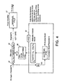
- Figure 4 is a flow diagram illustrating the preferred method of accounting for both the non-linearity of power amplifier 12 and attenuator 44.
- processor 32 uses a power amplifier (PA) inverse model and an attenuator inverse model in order to generate multiplying factors which are converted to analog form by converter 36 and transmitted over conductor 46 to attenuator 44.
- PA power amplifier
- Attenuator 44 multiplies the inputs from conductors 42 and 46 in the manner previously described.
- Attenuator 44 inherently contains a non-linear transfer function.
- the non-linearity is substantially reduced by using the attenuator inverse model in order to generate the multiplying factors transmitted over conductor 46.
- the attenuator inverse model defines a non-linear transfer function which is the inverse of the non-linear transfer function of attenuator 44.
- the signals on conductor 46 adjust for the nonlinear transfer function of attenuator 44 in order to reduce distortion in the output signal.
- both the attenuator inverse model and the power amplifier inverse model are based on a hyperbolic tangent function.
Landscapes
- Physics & Mathematics (AREA)
- Algebra (AREA)
- General Physics & Mathematics (AREA)
- Mathematical Analysis (AREA)
- Mathematical Optimization (AREA)
- Pure & Applied Mathematics (AREA)
- Nonlinear Science (AREA)
- Engineering & Computer Science (AREA)
- Power Engineering (AREA)
- Transmitters (AREA)
- Amplifiers (AREA)
- Digital Transmission Methods That Use Modulated Carrier Waves (AREA)
Abstract
Description







| Frequency [Mhz] | a | b |
| 118 | 436.8825 | 0.84121 |
| 123 | 476.0253 | 0.81249 |
| 128 | 494.7972 | 0.79766 |
| 133 | 467.7119 | 0.83079 |
| 135 | 486.3059 | 0.80158 |
| 137 | 479.877 | .80253 |
Claims (13)
- Apparatus for reducing distortion in a transmitter radio signal suitable for use in an aviation radio transmitter transmitting within a predetermined range of frequencies comprising in combination:a component defining a first nonlinear transfer function;a source of an input signal containing information to be transmitted; anda signal converter responsive to the input signal to generate a first signal including said information and defining a second nonlinear transfer function related to said first nonlinear transfer function, said component being responsive to said first signal to reduce distortion in the transmitter radio signal.
- Apparatus, as claimed in claim 1, wherein said signal converter comprises;a signal processor arranged to generate a second signal representing multiplying factors related to said second nonlinear transfer function; anda multiplier arranged to generate said first signal by performing a multiplication function with said multiplying factors.
- Apparatus, as claimed in claim 2, wherein said signal converter comprises an upconverter arranged to generate a radio frequency signal embodying said information and wherein said multiplier multiplies said multiplying factors times said radio frequency signal, and/or
wherein said signal processor upconverts said input signal from baseband to an intermediate frequency (IF) signal and
wherein said converter comprises an IF filter arranged to filter said IF signal,
wherein the IF filter is arranged to filter undesired side bands from said IF signal, and/or
wherein said signal processor comprises a store arranged to store coefficients defining at least in part said multiplying factors, and
wherein the coefficients vary with the frequencies within said predetermined range of frequencies. - Apparatus, as claimed in claim 2, wherein said multiplier comprises an attenuator
- Apparatus as claimed in claim 4, wherein said attenuator defines a third nonlinear transfer function.
- Apparatus, as claimed in claim 5, wherein said multiplying factors define at least in part a fourth nonlinear function related to said third nonlinear transfer function so that said first signal is modified to adjust for said third nonlinear transfer function.
- Apparatus, as claimed in claim 1, wherein said first nonlinear function comprises a hyperbolic tangent function, and/or
wherein said second nonlinear transfer function comprises an inverse hyperbolic tangent function. - A method of reducing distortion in a transmitter radio signal suitable for use in an aviation radio transmitter comprising a component defining a first nonlinear transfer function, said transmitter transmitting within a predetermined range of frequencies, said method comprising in combination:receiving an input signal containing information to be transmitted;generating in response to said input signal a first signal including said information and defining a second nonlinear transfer function related to said first nonlinear transfer function; andpassing said first signal through said component to reduce distortion in the transmitter radio signal.
- A method, as claimed in claim 9, wherein said generating comprises:generating a second signal representing multiplying factors related to said second nonlinear transfer function; andperforming a multiplication function with said multiplying factors in order to generate said first signal.
- A method, as claimed in claim 8, and further comprising upconverted said input signal to a radio frequency signal embodying said information and wherein said performing a multiplication function comprises multiplying said multiplying factors times said radio frequency signal, and further comprising:wherein said IF filtering comprises filtering undesired side bands from said IF signal, and/orupconverting said input signal from baseband to an intermediate frequency (IF) signal; andIF filtering said IF signal, and/or
wherein said generating a second signal comprises storing coefficients defining at least in part said multiplying factors, and
wherein said storing coefficients comprises storing coefficients varying with the frequencies within said predetermined range of frequencies. - A method, as claimed in claim 8, wherein said performing a multiplication function comprises attenuating, and/or
wherein said attenuating defines a third nonlinear transfer function. - A method, as claimed in claim 8, wherein said generating a second signal comprises generating a second signal representing multiplying factors defining at least in part a fourth nonlinear transfer function related to said third nonlinear transfer function so that said first signal is modified to adjust for said third nonlinear transfer function.
- A method, as claimed in claim 8, wherein said generating comprises generating a first signal defining an inverse hyperbolic tangent function related to said first nonlinear transfer function, and or
wherein said receiving comprises receiving a digital signal converted from an audio analog signal.
Applications Claiming Priority (2)
| Application Number | Priority Date | Filing Date | Title |
|---|---|---|---|
| US09/675,349 US6324383B1 (en) | 2000-09-29 | 2000-09-29 | Radio transmitter distortion reducing techniques |
| US675349 | 2000-09-29 |
Publications (2)
| Publication Number | Publication Date |
|---|---|
| EP1195893A2 true EP1195893A2 (en) | 2002-04-10 |
| EP1195893A3 EP1195893A3 (en) | 2003-11-12 |
Family
ID=24710069
Family Applications (1)
| Application Number | Title | Priority Date | Filing Date |
|---|---|---|---|
| EP01119650A Withdrawn EP1195893A3 (en) | 2000-09-29 | 2001-08-21 | Radio transmitter distortion reducing techniques |
Country Status (3)
| Country | Link |
|---|---|
| US (1) | US6324383B1 (en) |
| EP (1) | EP1195893A3 (en) |
| JP (1) | JP2002158592A (en) |
Families Citing this family (4)
| Publication number | Priority date | Publication date | Assignee | Title |
|---|---|---|---|---|
| US6489846B2 (en) * | 2000-05-25 | 2002-12-03 | Sony Corporation | Distortion compensating device and distortion compensating method |
| US20040142667A1 (en) * | 2003-01-21 | 2004-07-22 | Lochhead Donald Laird | Method of correcting distortion in a power amplifier |
| DE102004019366B4 (en) * | 2004-04-21 | 2006-05-04 | Infineon Technologies Ag | Circuit arrangement for a broadband mixer with predistortion and high linearity and method for broadband mixing |
| US7764729B1 (en) * | 2005-03-25 | 2010-07-27 | Lockheed Martin Corporation | Channelized amplifier system and method |
Family Cites Families (7)
| Publication number | Priority date | Publication date | Assignee | Title |
|---|---|---|---|---|
| US3878533A (en) * | 1974-03-22 | 1975-04-15 | Scope Inc | High speed analog to digital converter recirculating analog input for high speed output |
| DE3614785A1 (en) * | 1986-05-02 | 1988-01-21 | Rohde & Schwarz | AUXILIARY SYSTEM FOR EQUALIZING FREQUENCY-DEPENDENT NON-LINEAR SYSTEMS, IN PARTICULAR AMPLIFIERS |
| FR2707127A1 (en) * | 1993-06-29 | 1995-01-06 | Philips Laboratoire Electroniq | Digital transmission system with predisposition. |
| US5923712A (en) * | 1997-05-05 | 1999-07-13 | Glenayre Electronics, Inc. | Method and apparatus for linear transmission by direct inverse modeling |
| US6112062A (en) * | 1997-09-26 | 2000-08-29 | The Whitaker Corporation | Predistortion for high power amplifiers |
| US6075411A (en) * | 1997-12-22 | 2000-06-13 | Telefonaktiebolaget Lm Ericsson | Method and apparatus for wideband predistortion linearization |
| US6489846B2 (en) * | 2000-05-25 | 2002-12-03 | Sony Corporation | Distortion compensating device and distortion compensating method |
-
2000
- 2000-09-29 US US09/675,349 patent/US6324383B1/en not_active Expired - Lifetime
-
2001
- 2001-08-21 EP EP01119650A patent/EP1195893A3/en not_active Withdrawn
- 2001-09-07 JP JP2001271522A patent/JP2002158592A/en active Pending
Also Published As
| Publication number | Publication date |
|---|---|
| EP1195893A3 (en) | 2003-11-12 |
| JP2002158592A (en) | 2002-05-31 |
| US6324383B1 (en) | 2001-11-27 |
Similar Documents
| Publication | Publication Date | Title |
|---|---|---|
| JP3772031B2 (en) | Amplifier predistorter and amplifier | |
| US7418056B2 (en) | Digital predistorter using power series model | |
| US6240278B1 (en) | Scalar cost function based predistortion linearizing device, method, phone and basestation | |
| US5564086A (en) | Method and apparatus for enhancing an operating characteristic of a radio transmitter | |
| EP1695438B1 (en) | Amplifier linearization using non-linear predistortion | |
| US6240144B1 (en) | Apparatus and method of linearizing a power amplifier in a mobile radio communication system | |
| US8218678B2 (en) | Apparatus and method for digital pre-distortion, sharing feedback path in a multiple antenna wireless communication system | |
| CN100423447C (en) | Transmitter with transmitter chain phase adjustment based on pre-stored phase information | |
| US20020080891A1 (en) | Base station transmitter having digital predistorter and predistortion method thereof | |
| US7948311B2 (en) | Power series predistorter and control method thereof | |
| EP1511182B1 (en) | Table reference predistortor | |
| EP1193866A1 (en) | Predistortion type distortion compensation amplifier | |
| JPH04504345A (en) | Improvements within or relating to the amplifier | |
| EP1652294B1 (en) | Cartesian loop transmitter and method of adjusting an output level of such transmitter | |
| JP4230272B2 (en) | Distortion compensation device | |
| US8639197B2 (en) | Method and system to prevent harmonics from causing distortion in a communications system | |
| US6324383B1 (en) | Radio transmitter distortion reducing techniques | |
| US6940919B2 (en) | Bandpass predistortion method and apparatus for radio transmission | |
| US4995113A (en) | Device for processing an audio-frequency electrical signal | |
| US12580525B2 (en) | Transmission device and signal predistortion method thereof | |
| WO2024084629A1 (en) | System for compensating the non-linear distortion introduced by a radio power amplifier based on harmonic analysis | |
| CN115102509B (en) | Digital predistortion method and digital predistortion system | |
| TWI835565B (en) | Transceiver system capable of improving pre-distortion effect and control method thereof | |
| CN109856477B (en) | Method for exciting radio frequency active device and input optimization test system | |
| Braithwaite | Analog linearization techniques suitable for RF power amplifiers used in integrated transmitters |
Legal Events
| Date | Code | Title | Description |
|---|---|---|---|
| PUAI | Public reference made under article 153(3) epc to a published international application that has entered the european phase |
Free format text: ORIGINAL CODE: 0009012 |
|
| AK | Designated contracting states |
Kind code of ref document: A2 Designated state(s): AT BE CH CY DE DK ES FI FR GB GR IE IT LI LU MC NL PT SE TR |
|
| AX | Request for extension of the european patent |
Free format text: AL;LT;LV;MK;RO;SI |
|
| PUAL | Search report despatched |
Free format text: ORIGINAL CODE: 0009013 |
|
| AK | Designated contracting states |
Kind code of ref document: A3 Designated state(s): AT BE CH CY DE DK ES FI FR GB GR IE IT LI LU MC NL PT SE TR |
|
| AX | Request for extension of the european patent |
Extension state: AL LT LV MK RO SI |
|
| RAP1 | Party data changed (applicant data changed or rights of an application transferred) |
Owner name: NORTHROP GRUMMAN CORPORATION |
|
| RAP1 | Party data changed (applicant data changed or rights of an application transferred) |
Owner name: NORTHROP GRUMMAN CORPORATION |
|
| 17P | Request for examination filed |
Effective date: 20040511 |
|
| AKX | Designation fees paid |
Designated state(s): DE FI FR GB NL |
|
| RBV | Designated contracting states (corrected) |
Designated state(s): FI FR GB NL |
|
| REG | Reference to a national code |
Ref country code: DE Ref legal event code: 8566 |
|
| STAA | Information on the status of an ep patent application or granted ep patent |
Free format text: STATUS: THE APPLICATION IS DEEMED TO BE WITHDRAWN |
|
| 18D | Application deemed to be withdrawn |
Effective date: 20070301 |