EP1195887A2 - Electrostatic actuator driven slider displacement direction conversion mechanism - Google Patents
Electrostatic actuator driven slider displacement direction conversion mechanism Download PDFInfo
- Publication number
- EP1195887A2 EP1195887A2 EP01308549A EP01308549A EP1195887A2 EP 1195887 A2 EP1195887 A2 EP 1195887A2 EP 01308549 A EP01308549 A EP 01308549A EP 01308549 A EP01308549 A EP 01308549A EP 1195887 A2 EP1195887 A2 EP 1195887A2
- Authority
- EP
- European Patent Office
- Prior art keywords
- slider
- substrate
- elastic beam
- displaceable member
- displacement direction
- Prior art date
- Legal status (The legal status is an assumption and is not a legal conclusion. Google has not performed a legal analysis and makes no representation as to the accuracy of the status listed.)
- Granted
Links
Images



Classifications
-
- H—ELECTRICITY
- H02—GENERATION; CONVERSION OR DISTRIBUTION OF ELECTRIC POWER
- H02N—ELECTRIC MACHINES NOT OTHERWISE PROVIDED FOR
- H02N1/00—Electrostatic generators or motors using a solid moving electrostatic charge carrier
- H02N1/002—Electrostatic motors
- H02N1/006—Electrostatic motors of the gap-closing type
- H02N1/008—Laterally driven motors, e.g. of the comb-drive type
Definitions
- the present invention relates to a mechanism for converting the displacement direction of a slider which is driven by an electrostatic actuator in a structure on a surface of a substrate such as a silicon formed by using a technology such a photolithography.
- Figure 6 shows a known system in which a slider (a shuttle) 52 is displaced by using an interdigital electrostatic actuator 50 in order to continuously control the displacement of the slider 52 in a structure on the surface of a substrate formed of silicon or the like by using a technology such as photolithography.
- the electrostatic actuator 50 comprises a fixed side interdigital electrode 54 and a movable side interdigital electrode 55, the movable side interdigital electrode 55 is mounted on a fitting portion 53 at an end of the slider 52, and the slider 52 is displaced in a direction parallel to a substrate surface 51 by generating the electrostatic force between the interdigital electrodes 54, 55.
- the displacement is small, and the continuous control is less easily implemented, and the slider cannot be displaced in a direction which separates it from the substrate surface.
- An object of the present invention is to provide a slider displacement direction conversion mechanism in an electrostatic actuator in which the displacement direction of the slider can be converted to the perpendicular direction with respect to the substrate surface.
- Another object of the present invention is to provide a slider displacement direction conversion mechanism in an electrostatic actuator in which displacement of the slider in the direction parallel to the substrate surface is prevented and displacement in the upwardly perpendicular direction with respect to the substrate surface is increased.
- a slider displacement direction conversion mechanism in an electrostatic actuator in accordance with the invention comprises at least one electrostatic actuator which generates electrostatic force parallel to the substrate surface, at least one slider which is displaced under the force from the electrostatic actuator, and at least one elastic beam fixed to the substrate supporting the slider, the elastic beam has displaceable members which entirely or locally support the slider, and the displaceable members are characterised in that they are easily displaced in a direction different from the displacement direction when the slider is subjected to the force in the displacement direction.
- the slider displacement direction conversion mechanism preferably has a leaf spring structure in which one end of the elastic beam is fixed to the substrate in an inclined manner to the substrate surface, and the other end thereof is fixed to the slider, and the entire elastic beam forms the displaceable member.
- the elastic beam may have a strip like projecting piece which is inclined to the substrate surface on both ends thereof, the strip like projecting pieces on both ends forming the displaceable member, and the elastic beam being fixed to the substrate via the other strip like projecting piece.
- each strip like projecting piece is suitably formed by providing a notched portion in a part of the elastic beam, the displaceable member of the elastic beam is disposed so as to be easily displaced on a predetermined direction, and a plurality of elastic beams are disposed so that each displaceable member is easily displaced in the same direction.
- the plurality of elastic beams are disposed so as to support forward and rear portions of the slider, the forward and rear elastic beams are suitably disposed so that each displaceable member thereof is easily displaced in different directions.
- first and second sliders are disposed parallel to each other, the first slider is supported by the substrate via the displaceable member of the elastic beam fixed to the substrate, the second slider is supported by the first slider via the displaceable member of the elastic beam, and driving forces in the reverse direction to each other are given from first and second electrostatic actuators to the first and second sliders so that the displacement in the direction parallel to the substrate surface of the second slider is cancellled, and the displacement in the upwardly perpendicular direction with respect to the substrate surface is increased.
- two of the first sliders are supported in parallel by the substrate via the displaceable member of the outer elastic beam fixed to the substrate, one of the second sliders is disposed between the two first sliders, the second slider is respectively supported by the two first sliders via the displaceable member of the inner elastic beam, the displaceable member of the outer elastic beam is a plate-like displaceable member inclined at a counterclockwise angle with respect to the substrate while the displaceable member of the inner elastic beam is a plate-like displaceable member inclined at a clockwise angle from the substrate.
- the elastic beam supporting the slider is subjected to the force to generate the displacement parallel to the substrate.
- the displaceable member of the elastic beam supporting the slider is easily displaced in the direction different from the force applying direction, the displaceable member of the elastic beam is displaced by a specific angle with respect to the direction of the force.
- the slider supported by the displaceable member of the elastic beam is displaced so as to have a component of motion in the perpendicular direction with respect to the substrate.
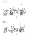
- a slider displacement direction conversion mechanism 1 comprises two pairs of elastic beams 12 having two displaceable members 11 on both end faces thereof with an appropriate space therebetween as shown in Fig. 1b or Fig. 2, and a slider 13 is disposed so as to be located on a tip of one displaceable member 11 of each elastic beam 12.
- the number of the elastic beams may be arbitrarily determined but at least three.
- the displaceable members 11 comprise a strip-like projecting piece disposed on both end faces of the elastic beam 12 in the same direction inclined at a counterclockwise angle with respect to a substrate. 14 in the figure.
- the strip-like projecting piece forming the displaceable members 11 is a member which is easily displaced in a direction different from the displacement direction when the slider is subjected to the force in the displacement direction, and the strip-like projecting piece is formed by providing a notched portion in a part of the elastic beam 12.
- electrostatic actuator 2 which generates the electrostatic force parallel to a substrate surface is disposed on the substrate 14, the electrostatic actuator 2 comprises a fixed side interdigital electrode and a movable side interdigital electrode similar to those in Fig. 6, the movable side interdigital electrode is mounted on a fitting portion 13a at an end of the slider 13, and the slider 13 is displaced in the horizontal direction with respect to the surface of the substrate 14 by generating the electrostatic force between the fixed side interdigital electrode and the movable side interdigital electrode.
- the electrostatic actuator 2, the slider 13 and the elastic beam 12 are manufactured by using the technology such as photolithography.
- the displaceable members 11 of the elastic beam 12 are inclined to the surface of the substrate 14 as described above, one of the displaceable members 11 is fixed to the slider 13, and the other of the displaceable members 11 is fixed to a fixed portion (not shown in the figure) which is integratedly formed on the substrate 14 in the horizontal direction.
- the displaceable member 11 is shown as a leaf spring 5 in Fig. 1a, and a fixed end 5a thereof is fixed to the substrate 14 in an inclined manner by the fitting angle q with respect to the normal direction of the substrate 14, and a tip 5b thereof is fixed to the slider 13 or the elastic beam.
- the electrostatic force F is applied to the tip 5b as shown in Fig. 1a.
- the electrostatic force F generates the force component F x0 in the width direction of the leaf spring 5 and the force component F 20 in the thickness direction orthogonal to the width direction of the leaf spring 5.
- the leaf spring 5 has a high rigidity in the force direction of F x0 , and has a relatively low rigidity in the force direction of F z0 , and the leaf spring is little displaced in the force direction of F x0 , but mainly displaced in the force direction of F x0 .
- the displaceable member 11 comprises the strip-like projecting piece disposed on both end faces of the elastic beam 12 in the same direction with a counterclockwise angle of inclination with respect to the surface of the substrate 14, the slider 13 is fixed to the tip of one displaceable member 11, and the other displaceable member 11 is fixed to the substrate 14, and as shown in Fig. 2, when the slider 13 is subjected to the electrostatic force F in the left direction parallel to the surface of the substrate 14, the displaceable members 11 disposed on a plurality of elastic beams 12 are displaced in the same direction, and as a result, the slider 13 is displaced upward to the left while constantly maintaining the same angle of inclination with respect to the substrate 14, and the distance from the substrate 14 is increased, accordingly.
- Fig. 3 shows another embodiment of the slider displacement direction conversion mechanism in the electrostatic actuator of the present invention.
- two pairs of elastic beams 22 having two displaceable members 21 on both end faces are disposed with a suitable space therebetween, and a slider 23 is disposed so as to be located on a tip of one displaceable member 21 of each elastic beam 22.
- the displaceable members 21 comprise strip-like projecting piece disposed on both end faces of the elastic beam 22 at different angles from each other with respect to the substrate 24.
- An electrostatic actuator 2 the slider 23 and the elastic beam 21 are disposed on the substrate 24 by using the technology such as photolithography, the slider 23 has a fitting portion 23a with a movable side interdigital electrode mounted on an end thereof, and the electrostatic actuator 2 generates the electrostatic force between the fixed side interdigital electrode and the movable side interdigital electrode, and displaces the slider 23 in the horizontal direction with respect to the surface of the substrate 24.
- the displaceable members 21 disposed on the plurality of elastic beams 22 are displaced in different directions, and as a result, the slider 23 is inclined at a counterclockwise angle with respect to the substrate 24, and the distance from the substrate 24 is changed thereby.
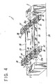
- Fig. 4 shows still another embodiment of the slider displacement direction conversion mechanism in the electrostatic actuator of the present invention.
- the slider displacement direction conversion mechanism 1 in the electrostatic actuator comprises two outer sliders 33 disposed on a substrate 34 parallel to each other, one inner slider 36 disposed between the two outer sliders 33, total four sets of outer elastic beams 32 with each set thereof comprising one pair of the outer elastic beams supporting the two outer sliders 33, total four sets of inner elastic beams 35 with each set thereof comprising one pair of inner elastic beams supported by the outer sliders 33, total four fixed portions 39 integratedly disposed on the substrate 34 in the perpendicular direction in the vicinity of side walls of the outer sliders 33, and two electrostatic actuators 2 disposed on the substrate 34 facing both sides in the axial direction of the outer sliders 33 and the inner slider 36.
- the electrostatic actuators 2, the outer sliders 33, the inner slider 36, the outer elastic beams 32, the inner elastic beams 35, and the fixed portions 39 are disposed on the substrate 34 by using the technology such as photolithography, the outer sliders 33 and the inner slider 36 have fitting portions 33a, 36a with a movable interdigital electrode mounted on ends thereof, and the electrostatic actuators 2 generate the electrostatic force between the fixed side interdigital electrode and the movable side interdigital electrode, and displace the outer sliders 33 and the inner slider 36 in the horizontal direction with respect to the surface of the substrate 34.
- the outer sliders 33, the inner slider 36, the outer elastic beams 32, the inner elastic beams 35 and the fixed portions 37 are symmetrical to the axis in the axial direction.
- the pair of outer elastic beams 32 are disposed parallel to each other, and the displaceable members 31 which are formed of the strip-like projecting pieces similar to those shown in Fig. 2 and inclined at a counterclockwise angle with respect to the substrate 34 are disposed on both end faces of the outer elastic beams 32.
- the outer sliders 33 are supported by the substrate 34 via one elastic beam 32 of the pair of outer elastic beams 32, the connection plates 38, the other elastic beam 32 of the pair of outer elastic beams 32, and the fixed portions 39.
- the pair of inner elastic beams 35 are disposed parallel to each other, and the displaceable members 37 which are symmetrical to the displaceable members 31 disposed on both end faces of the outer elastic beams 32, formed of the strip-like projecting pieces and inclined at a clockwise angle with respect to the substrate 34 are respectively formed on both side surfaces of the inner elastic beams 35.
- One elastic beam 35 of the pair of inner elastic beams 35 is fixed to an inner side wall of the outer slider 33 via the displaceable member 37 thereof, the other elastic beam 35 of the pair of inner elastic beams 35 is fixed to the inner slider 36 via the displaceable member 37 thereof, and the displaceable members 37 on the end face on the opposite side of the pair of inner elastic beams 35 are fixed to the connection plates 38, respectively.
- the inner slider 36 is supported by the outer sliders 33 via the other elastic beam 35 of the pair of inner elastic beams 35, the connection plates 38, and one elastic beam 35 of the pair of inner elastic beams 35.
- the displaceable members 31 which are formed of the strip-like projecting pieces and inclined at a counterclockwise angle with respect to the substrate 34 are formed on the outer elastic beams 32 which support the outer sliders 33 and are supported by the substrate 34
- the displaceable members 37 which are formed of the strip-like projecting pieces and inclined at a clockwise angle with respect to the substrate 34 are formed on the inner elastic beams 35 which support the inner slider 36 and are supported by the outer sliders 33.
- Fig. 5 shows further another embodiment of the slider displacement direction conversion mechanism in the electrostatic actuator of the present invention.
- the embodiment shown in Fig. 5 has basically the same structure as that of the embodiment shown in Fig. 2, except that an entire elastic beam 41 forms a displaceable member.
- the elastic beams 41 according to the embodiment shown in Fig. 5 have a leaf spring structure in which one end thereof is fixed to a substrate 44 in an inclined manner with respect to the substrate surface thereof, and the other end thereof is fixed to the slider 43, and the entire elastic beams 41 form the displaceable members.
- the slider 43 has a fitting portion 43a with a movable side interdigital electrode mounted on an end thereof, and the slider 43 is displaced in the horizontal direction with respect to the surface of the substrate 44 by generating the electrostatic force between the fixed side interdigital electrode and the movable side interdigital electrode of the electrostatic actuator 2.
Landscapes
- Micromachines (AREA)
- General Electrical Machinery Utilizing Piezoelectricity, Electrostriction Or Magnetostriction (AREA)
Abstract
Description
Claims (7)
- A slider displacement direction conversion mechanism for at least one slider which is displaced under electrostatic force parallel to a substrate surface generated by an electrostatic actuator, the slider being supported by at least one elastic beam fixed to the substrate supporting said slider, wherein the elastic beam has at least one displaceable member which supports the slider, and wherein the displaceable member is easily displaced in a direction different from a displacement direction when the slider is subjected to a force in the displacement direction.
- A slider displacement direction conversion mechanism according to Claim 1, wherein the elastic beam has a leaf spring structure and one end of the elastic beam is fixed to the substrate at an incline to the substrate surface, and the other end is fixed to the slider.
- A slider displacement direction conversion mechanism according to Claim 2, wherein the elastic beam has a strip-like projecting piece which is inclined to the substrate surface at both ends thereof, and wherein the strip-like projecting pieces form the displaceable members, and the elastic beam is fixed to the slider by one strip-like projecting piece and to the substrate via said other strip-like projecting piece.
- A slider displacement direction conversion mechanism according to Claim 3, wherein each strip-like projecting piece is formed by providing a notched portion in a part of said elastic beam.
- A slider displacement direction conversion mechanism according to any preceding claim, wherein the or each displaceable member of the elastic beam is disposed so as to be easily displaced in a predetermined direction, and a plurality of elastic beams are disposed so that each displaceable member thereof is easily displaced in the same direction.
- A slider displacement direction conversion mechanism according to any preceding claim, wherein there are first and second sliders disposed parallel to each other, the first slider is supported by the substrate via a first displaceable member of the elastic beam which is fixed to the substrate, and the second slider is supported by the first slider via a second displaceable member of the elastic beam, and wherein first and second electrostatic actuators provide driving forces in opposite directions to the first and second sliders so that displacement in the direction parallel to the substrate surface of the second slider is prevented and displacement in the upwardly perpendicular direction with respect to the substrate surface is increased.
- A slider displacement direction conversion mechanism according to Claim 6, wherein two first sliders are supported in parallel to each other by the substrate via a displaceable member of an outer elastic beam fixed to the substrate, wherein one of two second sliders is disposed between the two first sliders, and said second slider is supported by the two first sliders via a displaceable member of an inner elastic beam, wherein the displaceable member of the outer elastic beam is a plate-like displaceable member inclined at a counterclockwise angle with respect to the substrate, and wherein the displaceable member of the inner elastic beam is a plate-like displaceable member inclined at a clockwise angle with respect to the substrate.
Applications Claiming Priority (2)
| Application Number | Priority Date | Filing Date | Title |
|---|---|---|---|
| JP2000306445A JP3533443B2 (en) | 2000-10-05 | 2000-10-05 | Motion direction conversion mechanism of electrostatic actuator |
| JP2000306445 | 2000-10-05 |
Publications (3)
| Publication Number | Publication Date |
|---|---|
| EP1195887A2 true EP1195887A2 (en) | 2002-04-10 |
| EP1195887A3 EP1195887A3 (en) | 2003-09-24 |
| EP1195887B1 EP1195887B1 (en) | 2008-08-06 |
Family
ID=18787133
Family Applications (1)
| Application Number | Title | Priority Date | Filing Date |
|---|---|---|---|
| EP01308549A Expired - Lifetime EP1195887B1 (en) | 2000-10-05 | 2001-10-05 | Electrostatic actuator driven slider displacement direction conversion mechanism |
Country Status (4)
| Country | Link |
|---|---|
| US (1) | US6781280B2 (en) |
| EP (1) | EP1195887B1 (en) |
| JP (1) | JP3533443B2 (en) |
| DE (1) | DE60135194D1 (en) |
Cited By (1)
| Publication number | Priority date | Publication date | Assignee | Title |
|---|---|---|---|---|
| US6781280B2 (en) * | 2000-10-05 | 2004-08-24 | National Institute Of Advanced Industrial Science And Technology | Slider displacement direction conversion mechanism in electrostatic actuator |
Families Citing this family (4)
| Publication number | Priority date | Publication date | Assignee | Title |
|---|---|---|---|---|
| JP4143729B2 (en) * | 2003-03-13 | 2008-09-03 | 独立行政法人産業技術総合研究所 | 3D electrostatic actuator |
| JP4534010B2 (en) * | 2004-06-15 | 2010-09-01 | 独立行政法人産業技術総合研究所 | Plasma etching method |
| CN102897704B (en) * | 2012-10-17 | 2015-03-04 | 东南大学 | Micro-electro-mechanical comb tooth mechanism capable of adjusting tooth gaps by electrostatic force |
| JP6953117B2 (en) * | 2016-07-04 | 2021-10-27 | エドワード・パクチャン | Light modulators for MEMS displays |
Family Cites Families (6)
| Publication number | Priority date | Publication date | Assignee | Title |
|---|---|---|---|---|
| JP2682181B2 (en) | 1990-02-02 | 1997-11-26 | 日本電気株式会社 | Micro movable mechanical mechanism |
| JPH05116757A (en) * | 1991-10-24 | 1993-05-14 | Ricoh Co Ltd | Transport mechanism |
| US5434464A (en) | 1994-05-23 | 1995-07-18 | Mcnc | Unidirectional supporting structure for microelectromechanical transducers |
| US5862003A (en) * | 1995-06-23 | 1999-01-19 | Saif; Muhammad T. A. | Micromotion amplifier |
| AU7289801A (en) * | 2000-04-11 | 2001-10-23 | Sandia Corp | Microelectromechanical apparatus for elevating and tilting a platform |
| JP3533443B2 (en) * | 2000-10-05 | 2004-05-31 | 独立行政法人産業技術総合研究所 | Motion direction conversion mechanism of electrostatic actuator |
-
2000
- 2000-10-05 JP JP2000306445A patent/JP3533443B2/en not_active Expired - Lifetime
-
2001
- 2001-10-05 US US09/970,939 patent/US6781280B2/en not_active Expired - Fee Related
- 2001-10-05 EP EP01308549A patent/EP1195887B1/en not_active Expired - Lifetime
- 2001-10-05 DE DE60135194T patent/DE60135194D1/en not_active Expired - Lifetime
Cited By (1)
| Publication number | Priority date | Publication date | Assignee | Title |
|---|---|---|---|---|
| US6781280B2 (en) * | 2000-10-05 | 2004-08-24 | National Institute Of Advanced Industrial Science And Technology | Slider displacement direction conversion mechanism in electrostatic actuator |
Also Published As
| Publication number | Publication date |
|---|---|
| US20020050763A1 (en) | 2002-05-02 |
| EP1195887B1 (en) | 2008-08-06 |
| JP2002119072A (en) | 2002-04-19 |
| DE60135194D1 (en) | 2008-09-18 |
| US6781280B2 (en) | 2004-08-24 |
| JP3533443B2 (en) | 2004-05-31 |
| EP1195887A3 (en) | 2003-09-24 |
Similar Documents
| Publication | Publication Date | Title |
|---|---|---|
| KR101073175B1 (en) | Shape-variable mirror and light control device having the shape-variable mirror | |
| KR20010048133A (en) | Optical Switch using Micro Structures | |
| US5206557A (en) | Microelectromechanical transducer and fabrication method | |
| US6215222B1 (en) | Optical cross-connect switch using electrostatic surface actuators | |
| EP0567617B1 (en) | Piezoelectric and electrostrictive actuators | |
| JPH05219760A (en) | Electrostatic actuator | |
| US20040145854A1 (en) | Electrostatic actuator | |
| WO2003014784A2 (en) | Micro-electro-mechanical mirror devices having a high linear mirror fill factor | |
| US8022596B2 (en) | Guided electromechanical motor | |
| US20210061642A1 (en) | Mems comprising a movable structural element, and mems array | |
| EP1195887B1 (en) | Electrostatic actuator driven slider displacement direction conversion mechanism | |
| JP2004053839A (en) | Light switching device | |
| US6998758B2 (en) | Deformable MEMS mirror with membrane actuated by application of torque | |
| US6833652B2 (en) | Balanced micromechanical device having two degrees of motion | |
| US7579747B2 (en) | Electrostatic actuator | |
| EP0530822B1 (en) | Guide device for vibration driven motor | |
| CA2480944C (en) | Movable mirror device and dispersion compensator | |
| WO2025155345A3 (en) | Micro-electromechanical systems switch with beam movement orthogonal to force | |
| US6774539B2 (en) | High pressure, high speed actuator | |
| JP4621577B2 (en) | Electrostatic actuator and driving method thereof | |
| JP4396299B2 (en) | Mirror system and optical switch | |
| JP4254580B2 (en) | Electrode structure and optical device | |
| CA2370044A1 (en) | Electrostatic microactuator with offset and/or inclined comb drive fingers | |
| JP2629651B2 (en) | Mirror deflector | |
| US12368394B2 (en) | Stacked actuator comprising longitudinal and shear actuator sections |
Legal Events
| Date | Code | Title | Description |
|---|---|---|---|
| PUAI | Public reference made under article 153(3) epc to a published international application that has entered the european phase |
Free format text: ORIGINAL CODE: 0009012 |
|
| AK | Designated contracting states |
Kind code of ref document: A2 Designated state(s): AT BE CH CY DE DK ES FI FR GB GR IE IT LI LU MC NL PT SE TR |
|
| AX | Request for extension of the european patent |
Free format text: AL;LT;LV;MK;RO;SI |
|
| PUAL | Search report despatched |
Free format text: ORIGINAL CODE: 0009013 |
|
| AK | Designated contracting states |
Kind code of ref document: A3 Designated state(s): AT BE CH CY DE DK ES FI FR GB GR IE IT LI LU MC NL PT SE TR |
|
| AX | Request for extension of the european patent |
Extension state: AL LT LV MK RO SI |
|
| 17P | Request for examination filed |
Effective date: 20040206 |
|
| AKX | Designation fees paid |
Designated state(s): CH DE GB LI |
|
| 17Q | First examination report despatched |
Effective date: 20061128 |
|
| GRAP | Despatch of communication of intention to grant a patent |
Free format text: ORIGINAL CODE: EPIDOSNIGR1 |
|
| GRAS | Grant fee paid |
Free format text: ORIGINAL CODE: EPIDOSNIGR3 |
|
| GRAA | (expected) grant |
Free format text: ORIGINAL CODE: 0009210 |
|
| AK | Designated contracting states |
Kind code of ref document: B1 Designated state(s): CH DE GB LI |
|
| REG | Reference to a national code |
Ref country code: GB Ref legal event code: FG4D |
|
| REG | Reference to a national code |
Ref country code: CH Ref legal event code: NV Representative=s name: ING. MARCO ZARDI C/O M. ZARDI & CO. S.A. Ref country code: CH Ref legal event code: EP |
|
| REF | Corresponds to: |
Ref document number: 60135194 Country of ref document: DE Date of ref document: 20080918 Kind code of ref document: P |
|
| PLBE | No opposition filed within time limit |
Free format text: ORIGINAL CODE: 0009261 |
|
| STAA | Information on the status of an ep patent application or granted ep patent |
Free format text: STATUS: NO OPPOSITION FILED WITHIN TIME LIMIT |
|
| 26N | No opposition filed |
Effective date: 20090507 |
|
| PGFP | Annual fee paid to national office [announced via postgrant information from national office to epo] |
Ref country code: DE Payment date: 20101022 Year of fee payment: 10 |
|
| PGFP | Annual fee paid to national office [announced via postgrant information from national office to epo] |
Ref country code: GB Payment date: 20101021 Year of fee payment: 10 |
|
| PGFP | Annual fee paid to national office [announced via postgrant information from national office to epo] |
Ref country code: CH Payment date: 20111024 Year of fee payment: 11 |
|
| REG | Reference to a national code |
Ref country code: CH Ref legal event code: PL |
|
| GBPC | Gb: european patent ceased through non-payment of renewal fee |
Effective date: 20121005 |
|
| PG25 | Lapsed in a contracting state [announced via postgrant information from national office to epo] |
Ref country code: LI Free format text: LAPSE BECAUSE OF NON-PAYMENT OF DUE FEES Effective date: 20121031 Ref country code: DE Free format text: LAPSE BECAUSE OF NON-PAYMENT OF DUE FEES Effective date: 20130501 Ref country code: CH Free format text: LAPSE BECAUSE OF NON-PAYMENT OF DUE FEES Effective date: 20121031 Ref country code: GB Free format text: LAPSE BECAUSE OF NON-PAYMENT OF DUE FEES Effective date: 20121005 |
|
| REG | Reference to a national code |
Ref country code: DE Ref legal event code: R119 Ref document number: 60135194 Country of ref document: DE Effective date: 20130501 |