EP1195842A1 - Antenna structure of portable radio - Google Patents
Antenna structure of portable radio Download PDFInfo
- Publication number
- EP1195842A1 EP1195842A1 EP00900397A EP00900397A EP1195842A1 EP 1195842 A1 EP1195842 A1 EP 1195842A1 EP 00900397 A EP00900397 A EP 00900397A EP 00900397 A EP00900397 A EP 00900397A EP 1195842 A1 EP1195842 A1 EP 1195842A1
- Authority
- EP
- European Patent Office
- Prior art keywords
- antenna
- portable radio
- radio equipment
- cabinet
- polarization
- Prior art date
- Legal status (The legal status is an assumption and is not a legal conclusion. Google has not performed a legal analysis and makes no representation as to the accuracy of the status listed.)
- Granted
Links
Images


Classifications
-
- H—ELECTRICITY
- H01—ELECTRIC ELEMENTS
- H01Q—ANTENNAS, i.e. RADIO AERIALS
- H01Q3/00—Arrangements for changing or varying the orientation or the shape of the directional pattern of the waves radiated from an antenna or antenna system
- H01Q3/02—Arrangements for changing or varying the orientation or the shape of the directional pattern of the waves radiated from an antenna or antenna system using mechanical movement of antenna or antenna system as a whole
- H01Q3/04—Arrangements for changing or varying the orientation or the shape of the directional pattern of the waves radiated from an antenna or antenna system using mechanical movement of antenna or antenna system as a whole for varying one co-ordinate of the orientation
- H01Q3/06—Arrangements for changing or varying the orientation or the shape of the directional pattern of the waves radiated from an antenna or antenna system using mechanical movement of antenna or antenna system as a whole for varying one co-ordinate of the orientation over a restricted angle
-
- H—ELECTRICITY
- H01—ELECTRIC ELEMENTS
- H01Q—ANTENNAS, i.e. RADIO AERIALS
- H01Q1/00—Details of, or arrangements associated with, antennas
- H01Q1/12—Supports; Mounting means
- H01Q1/22—Supports; Mounting means by structural association with other equipment or articles
- H01Q1/24—Supports; Mounting means by structural association with other equipment or articles with receiving set
- H01Q1/241—Supports; Mounting means by structural association with other equipment or articles with receiving set used in mobile communications, e.g. GSM
- H01Q1/242—Supports; Mounting means by structural association with other equipment or articles with receiving set used in mobile communications, e.g. GSM specially adapted for hand-held use
-
- H—ELECTRICITY
- H01—ELECTRIC ELEMENTS
- H01Q—ANTENNAS, i.e. RADIO AERIALS
- H01Q1/00—Details of, or arrangements associated with, antennas
- H01Q1/12—Supports; Mounting means
- H01Q1/22—Supports; Mounting means by structural association with other equipment or articles
- H01Q1/24—Supports; Mounting means by structural association with other equipment or articles with receiving set
- H01Q1/241—Supports; Mounting means by structural association with other equipment or articles with receiving set used in mobile communications, e.g. GSM
- H01Q1/242—Supports; Mounting means by structural association with other equipment or articles with receiving set used in mobile communications, e.g. GSM specially adapted for hand-held use
- H01Q1/243—Supports; Mounting means by structural association with other equipment or articles with receiving set used in mobile communications, e.g. GSM specially adapted for hand-held use with built-in antennas
- H01Q1/244—Supports; Mounting means by structural association with other equipment or articles with receiving set used in mobile communications, e.g. GSM specially adapted for hand-held use with built-in antennas extendable from a housing along a given path
-
- H—ELECTRICITY
- H01—ELECTRIC ELEMENTS
- H01Q—ANTENNAS, i.e. RADIO AERIALS
- H01Q1/00—Details of, or arrangements associated with, antennas
- H01Q1/12—Supports; Mounting means
- H01Q1/22—Supports; Mounting means by structural association with other equipment or articles
- H01Q1/24—Supports; Mounting means by structural association with other equipment or articles with receiving set
- H01Q1/241—Supports; Mounting means by structural association with other equipment or articles with receiving set used in mobile communications, e.g. GSM
- H01Q1/242—Supports; Mounting means by structural association with other equipment or articles with receiving set used in mobile communications, e.g. GSM specially adapted for hand-held use
- H01Q1/245—Supports; Mounting means by structural association with other equipment or articles with receiving set used in mobile communications, e.g. GSM specially adapted for hand-held use with means for shaping the antenna pattern, e.g. in order to protect user against rf exposure
-
- H—ELECTRICITY
- H01—ELECTRIC ELEMENTS
- H01Q—ANTENNAS, i.e. RADIO AERIALS
- H01Q3/00—Arrangements for changing or varying the orientation or the shape of the directional pattern of the waves radiated from an antenna or antenna system
- H01Q3/02—Arrangements for changing or varying the orientation or the shape of the directional pattern of the waves radiated from an antenna or antenna system using mechanical movement of antenna or antenna system as a whole
- H01Q3/04—Arrangements for changing or varying the orientation or the shape of the directional pattern of the waves radiated from an antenna or antenna system using mechanical movement of antenna or antenna system as a whole for varying one co-ordinate of the orientation
Definitions
- the present invention relates to an antenna structure for portable radio equipment, and more specifically, to an antenna structure for portable radio equipment that allows inclining an antenna to a desired angle in order to improve sensitivity of the portable radio equipment.
- Existing types of transmitting/receiving antennas of portable radio equipment include a whip antenna mounted in a longitudinal direction of a cabinet and a helical antenna.
- the most often adopted antenna for portable radio equipment currently commercially available in Japan is a whip and helical antenna having a structure that operates as a whip antenna when pulled out and in that, when retracted, a helical antenna operates that is provided on a tip of the whip antenna with an insulating material intervening therebetween.
- an inverted F antenna or the like is built into the cabinet as an antenna for reception diversity.
- antenna efficiency determined by an effective radiation area owing to the physical size and the structure of the antenna.
- antenna efficiency there is loss due to impedance mismatch with a radio unit and loss due to nonconformity of polarization plane and directivity in relation to an antenna that is a target of communication. Since the environment in which an antenna on mobile equipment of mobile communications such as portable radio equipment is installed or held constantly changes, directivity and plane of polarization vary constantly.
- An antenna of a base station that communicates with portable radio equipment through transmission and reception is configured with vertical polarization as the main polarization.
- Transmission waves from a transmitting/receiving antenna of the base station are repeatedly reflected and diffracted by various structures such as buildings before they arrive at a receiving antenna of portable radio equipment.
- Vertical polarization is generally known to be dominant as the main polarization of the waves arriving at portable radio equipment from the base station.
- the reception characteristic of the transmitting/receiving antenna of the base station it is obvious from the reversibility of the transmission/reception characteristic of the antenna that the greater the vertical polarization component in the waves arriving from portable radio equipment, the higher the gain of the antenna becomes.
- Whip antennas and the like formed on portable radio equipment have radiation patterns of various forms depending on an electrical length of an antenna element and a dimension of the cabinet.
- the main polarization is known to become vertical polarization in relation to the ground.
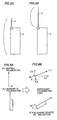
- Figs. 6A and 6B are diagrams related to the description of polarization loss when portable radio equipment is inclined.
- E ⁇ indicates an electric field level of vertical polarization
- E ⁇ indicates an electric field level of horizontal polarization when portable radio equipment 1 is erected vertically.
- the principal object of the present invention is to provide an antenna structure for portable radio equipment that can be formed with a small number of parts, that allows inclining of the antenna to a desired angle, and that can reduce loss due to nonconformity of polarization.
- the present invention is an antenna structure mounted on a cabinet of portable radio equipment including an antenna made of a conductor of elastic alloy and an inclining portion provided on a cabinet for inclining the antenna.
- the antenna has vertical polarization and the inclining portion inclines a polarization plane of the antenna to a direction vertical to the ground.
- the inclining portion includes a sliding member whose tip engages a lower portion of the antenna within the cabinet and which slides to incline the antenna.
- the inclining portion includes a stopping member whose upper end engagingly stops against the antenna outside the cabinet and which inclines the antenna.
- the inclining portion includes a disk member having a groove that is cut away departing from a center, and a lower portion of the antenna is inserted in the groove of the disk member and the disk member is rotated to incline the antenna.
- Another aspect of the present invention is an antenna structure mounted on a cabinet of portable radio equipment, characterized in that a polarization plane of an antenna having vertical polarization during a call and having a length of ⁇ /2 is inclined to a direction vertical to the ground.
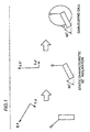
- Fig. 1 is a conceptual diagram of the present invention.
- an antenna that can be flexibly bent is provided to a cabinet of portable radio equipment 1 such that an electric field level E ⁇ of vertical polarization and an electric field level E ⁇ of horizontal polarization when portable radio equipment 1 is erected are made substantially equal to an electric field level E ⁇ ' of vertical polarization and an electric field level E ⁇ ' of horizontal polarization when portable radio equipment 1 is inclined, for instance, by 60° in use during a call, thereby reducing polarization loss.
- Fig. 2A is a diagram of an antenna structure of portable radio equipment according to one embodiment of the present invention viewed from the rear side
- Fig. 2B is a diagram of the portable radio equipment provided with a slide lever for inclining the antenna, viewed from the front.
- An antenna 3 shown in Figs. 2A and 2B utilizes nickel elastic alloy, for instance, and is flexible to any desired angle.
- a helical antenna 4 is provided in an upper portion of antenna 3, a lower portion of antenna 3 is held by a holding portion 5 as shown in Fig. 2A, and a slide lever 6 is provided above holding portion 5.
- An engaging portion 61 for engaging with antenna 3 is formed in a backside of slide lever 6.
- Slide lever 6 is configured such that it is slidable in a horizontal direction along a groove not shown.
- antenna 3 stands upright in relation to cabinet 2, and antenna 3 can be inclined to any desired angle by sliding slide lever 6 to the right or to the left.
- an elastic antenna 3 can be inclined by a desired angle by merely sliding slide lever 6.
- the caller may manipulate slide lever 6 to determine an angle of inclination of antenna 3 such that an angle with highest sensitivity can be obtained.
- antenna 3 be formed with elastic alloy and that slide lever 6 be provided, the number of parts can be reduced, and because of a complex mechanical structure, there is little risk of antenna 1 being broken even when dropped by mistake.
- Figs. 3A to 3C are diagrams showing an antenna structure according to the second embodiment of the present invention.
- a stopping member 7 that is slidable up and down is provided on an upper portion of a cabinet 2.
- an antenna 3 is formed by nickel elastic alloy as in the embodiment of Figs. 2A and 2B.
- antenna 3 is flexible to any given angle, and a tip of stopping member 7 engagingly stops against antenna 3 such that stopping member 7 may be moved up and down to incline antenna 3 to any desired angle.
- this embodiment also allows adjustment of the angle of inclination of antenna 3 such that sensitivity is maximized while a caller has portable radio equipment tilted in use during a call.
- FIGs. 4A and 4B are diagrams showing an antenna structure according to the third embodiment of the present invention.
- An antenna 3 is made of nickel elastic alloy, and has its lower portion held by a holding portion 5, and has a disk member 7 provided on its upper portion.
- a groove 71 that is cut away and departing from a center is formed in disk member 7, and antenna 3 is inserted in groove 71.
- a portion of a peripheral surface of disk member 7 protrudes from a cabinet 2, and when a caller touches that portion with a finger to rotate rotation member 7, antenna 3 slidably moves along groove 71 since groove 71 departs from a center, and the angle of inclination of antenna 3 changes.
- rotation member 7 When storing antenna 3 within cabinet 2, rotation member 7 is rotated so as to locate antenna 3 in the center of groove 71, and thus, antenna 3 is received in the cabinet.
- Figs. 5A and 5B are diagrams showing a further embodiment of the present invention. Specifically, Fig. 5A shows a ⁇ /4 type antenna, while Fig. 5B shows a ⁇ /2 type antenna.
- a length of an antenna 3 and a length in a longitudinal direction of a cabinet 2 is selected to be ⁇ /4 in the ⁇ /4 type antenna shown in Fig. 5A
- the length of antenna 3 alone is selected to be ⁇ /2 for the ⁇ /2 type antenna shown in Fig. 5B.
- a current closes in the vicinity of a portion where antenna 3 and cabinet 2 are joined so that a current hardly flows through cabinet 2 and the current flows through antenna 3 alone. Consequently, a greater reduction effect of polarization loss upon inclining of antenna 3 can be achieved.
- N is an integer
- ⁇ /2 such as ⁇ /2, ⁇ , 3/2• ⁇ for antenna 3. This is based on the fact that a frequency band used for a portable telephone in recent years is as high as 2 GHz and one wavelength is 15 cm, and that, at ⁇ /2, an antenna at 7.5 cm can be resonated.
- an antenna can be provided with flexibility by using elastic alloy as a conductor for the antenna, for instance, and the antenna can be bent during a call such that it is inclined in a direction vertical to the ground, thereby reducing loss due to nonconformity of polarization with respect to an antenna of a base station.
- no mechanism for inclining the antenna provided to the antenna itself is required so that the antenna should not be broken when dropped, and lighter weight can be achieved since the number of parts is small.
- the present invention can be applied effectively to an antenna that resonates at N times ⁇ /2.
Landscapes
- Engineering & Computer Science (AREA)
- Computer Networks & Wireless Communication (AREA)
- Support Of Aerials (AREA)
- Telephone Set Structure (AREA)
Abstract
Description
Polarization loss = 20 log10(E/E')dB
Claims (6)
- An antenna structure mounted on a cabinet of portable radio equipment, comprising:an antenna (3) made of a conductor of elastic alloy; andan inclining portion (6, 7, 8) provided on said cabinet for inclining said antenna.
- The antenna structure of portable radio equipment according to claim 1, characterized in thatsaid antenna has vertical polarization, andsaid inclining portion inclines a polarization plane of said antenna to a direction vertical to a ground.
- The antenna structure of portable radio equipment according to claim 2, whereinsaid inclining portion includes a sliding member (6) whose tip engages a lower portion of said antenna within said cabinet and which slides to incline the antenna.
- The antenna structure of portable radio equipment according to claim 2, whereinsaid inclining portion includes a stopping member (7) whose upper end engagingly stops against the antenna outside the cabinet and which inclines the antenna.
- The antenna structure of portable radio equipment according to claim 2, characterized in thatsaid inclining portion includes a disk member (8) having a groove (81) that is cut away departing from a center, anda lower portion of said antenna is inserted in the groove of said disk member and the rotation member is rotated to incline said antenna.
- An antenna structure mounted on a cabinet of portable radio equipment, characterized in thata polarization plane of an antenna having vertical polarization during a call and having a length of N times λ/2 (N is an integer) is inclined to a direction vertical to the ground.
Applications Claiming Priority (1)
| Application Number | Priority Date | Filing Date | Title |
|---|---|---|---|
| PCT/JP2000/000157 WO2001052349A1 (en) | 2000-01-14 | 2000-01-14 | Antenna structure of portable radio |
Publications (3)
| Publication Number | Publication Date |
|---|---|
| EP1195842A1 true EP1195842A1 (en) | 2002-04-10 |
| EP1195842A4 EP1195842A4 (en) | 2002-07-31 |
| EP1195842B1 EP1195842B1 (en) | 2003-10-29 |
Family
ID=11735575
Family Applications (1)
| Application Number | Title | Priority Date | Filing Date |
|---|---|---|---|
| EP00900397A Expired - Lifetime EP1195842B1 (en) | 2000-01-14 | 2000-01-14 | Antenna structure of portable radio |
Country Status (6)
| Country | Link |
|---|---|
| US (1) | US6577279B1 (en) |
| EP (1) | EP1195842B1 (en) |
| JP (1) | JP3792157B2 (en) |
| CN (1) | CN1203573C (en) |
| DE (1) | DE60006240T2 (en) |
| WO (1) | WO2001052349A1 (en) |
Families Citing this family (3)
| Publication number | Priority date | Publication date | Assignee | Title |
|---|---|---|---|---|
| US7187959B2 (en) * | 2003-11-25 | 2007-03-06 | Motorola, Inc. | Antenna structure for devices with conductive chassis |
| SG121020A1 (en) * | 2004-09-14 | 2006-04-26 | St Electronics Satcom & Sensor | Portable satllite terminal |
| JP7670782B1 (en) | 2023-11-16 | 2025-04-30 | Necプラットフォームズ株式会社 | Built-in antenna fixing part and wireless communication device |
Family Cites Families (18)
| Publication number | Priority date | Publication date | Assignee | Title |
|---|---|---|---|---|
| JPH01120108A (en) | 1987-11-02 | 1989-05-12 | Nec Corp | Radio terminal equipment antenna |
| JPH0247814U (en) | 1988-09-28 | 1990-04-03 | ||
| JPH0514027A (en) | 1991-07-03 | 1993-01-22 | Mitsubishi Electric Corp | Antenna system |
| JP2584154B2 (en) | 1991-08-21 | 1997-02-19 | 松下電器産業株式会社 | Mobile phone antenna |
| FR2701613B1 (en) | 1993-02-11 | 1995-03-31 | Alcatel Radiotelephone | Portable radiotelephone transceiver. |
| JPH06268547A (en) | 1993-03-10 | 1994-09-22 | Mitsubishi Electric Corp | Antenna system for portable radio equipment |
| US5523766A (en) * | 1993-11-05 | 1996-06-04 | At&T Corp. | Apparatus for maintaining antenna polarization in portable communication devices |
| JPH07307607A (en) | 1994-05-10 | 1995-11-21 | Junzo Fujita | Antenna for portable telephone set |
| US5559522A (en) | 1994-07-25 | 1996-09-24 | Motorola, Inc. | Antenna positioning apparatus capable of substantially vertical orientation |
| JPH08125418A (en) | 1994-10-26 | 1996-05-17 | Tokin Corp | antenna |
| US5590416A (en) | 1995-06-08 | 1996-12-31 | Ericsson Inc. | Canted antenna for a cellular radiotelephone |
| JPH08274525A (en) | 1995-03-31 | 1996-10-18 | Kokusai Electric Co Ltd | Telescopic antenna for portable radio |
| JP3674172B2 (en) | 1995-09-22 | 2005-07-20 | 三菱電機株式会社 | Antenna device |
| JPH1013123A (en) | 1996-06-25 | 1998-01-16 | Hitachi Metals Ltd | Portable telephone set antenna |
| DE19644648C1 (en) * | 1996-10-26 | 1998-05-20 | Bosch Gmbh Robert | Radio receiver |
| WO1999035708A1 (en) * | 1998-01-05 | 1999-07-15 | The Furukawa Electric Co., Ltd. | Antenna device for portable telephone, and method of manufacture |
| KR100345534B1 (en) * | 1998-10-07 | 2002-10-25 | 삼성전자 주식회사 | Antenna unit installed on the flip cover in flip-up phones |
| US6104350A (en) * | 1999-03-22 | 2000-08-15 | Motorola, Inc. | Retractable angled antenna assembly |
-
2000
- 2000-01-14 CN CNB008044694A patent/CN1203573C/en not_active Expired - Fee Related
- 2000-01-14 EP EP00900397A patent/EP1195842B1/en not_active Expired - Lifetime
- 2000-01-14 DE DE60006240T patent/DE60006240T2/en not_active Expired - Fee Related
- 2000-01-14 US US09/936,441 patent/US6577279B1/en not_active Expired - Fee Related
- 2000-01-14 WO PCT/JP2000/000157 patent/WO2001052349A1/en not_active Ceased
- 2000-01-14 JP JP2001552469A patent/JP3792157B2/en not_active Expired - Fee Related
Also Published As
| Publication number | Publication date |
|---|---|
| DE60006240D1 (en) | 2003-12-04 |
| DE60006240T2 (en) | 2004-07-29 |
| CN1342337A (en) | 2002-03-27 |
| JP3792157B2 (en) | 2006-07-05 |
| WO2001052349A1 (en) | 2001-07-19 |
| EP1195842A4 (en) | 2002-07-31 |
| CN1203573C (en) | 2005-05-25 |
| US6577279B1 (en) | 2003-06-10 |
| EP1195842B1 (en) | 2003-10-29 |
Similar Documents
| Publication | Publication Date | Title |
|---|---|---|
| EP1076919B1 (en) | Multiple frequency band antenna | |
| US5945954A (en) | Antenna assembly for telecommunication devices | |
| US6201501B1 (en) | Antenna configuration for a mobile station | |
| US7225003B2 (en) | Mobile terminal including first and second housings and an antenna | |
| US6683578B2 (en) | Built-in antenna of portable radio apparatus | |
| WO1999013528A1 (en) | Loop antenna assembly for telecommunications devices | |
| GB2399683A (en) | Multiple antenna diversity on mobile telephone handsets, PDAs and other electrically small radio platforms | |
| US6694151B2 (en) | Antenna apparatus for digital cameras incorporating wideband RF transceivers | |
| US6882320B2 (en) | Diversity antenna apparatus for portable wireless terminal | |
| US6681125B1 (en) | Wireless telecommunication terminal | |
| JP2002508900A (en) | Wireless equipment | |
| JPS61205004A (en) | Portable radio equipment | |
| US20100111143A1 (en) | Portable radio | |
| US6405064B1 (en) | Portable wireless device | |
| US6577279B1 (en) | Antenna structure of portable radio | |
| JP4069271B2 (en) | Patch antenna for terminal device for clothing and antenna device for terminal device for clothing using the same | |
| JPWO2001052349A1 (en) | Antenna structure of a portable radio | |
| JP2001230613A (en) | Antenna device and portable wireless device | |
| JP4105728B2 (en) | Wideband monopole antenna assembly | |
| WO2006013843A1 (en) | Cellular phone | |
| JP2003037411A (en) | Portable radio equipment | |
| JPH09219676A (en) | Portable radio | |
| JP4318605B2 (en) | Foldable mobile phone | |
| JP2002237762A (en) | transceiver | |
| KR20030009067A (en) | Wire Antenna for portable Wireless Communication Terminal |
Legal Events
| Date | Code | Title | Description |
|---|---|---|---|
| PUAI | Public reference made under article 153(3) epc to a published international application that has entered the european phase |
Free format text: ORIGINAL CODE: 0009012 |
|
| 17P | Request for examination filed |
Effective date: 20011011 |
|
| AK | Designated contracting states |
Kind code of ref document: A1 Designated state(s): AT BE CH CY DE DK ES FI FR GB GR IE IT LI LU MC NL PT SE |
|
| A4 | Supplementary search report drawn up and despatched |
Effective date: 20020619 |
|
| AK | Designated contracting states |
Kind code of ref document: A4 Designated state(s): AT BE CH CY DE DK ES FI FR GB GR IE IT LI LU MC NL PT SE |
|
| RIC1 | Information provided on ipc code assigned before grant |
Free format text: 7H 01Q 1/24 A, 7H 01Q 3/04 B, 7H 01Q 3/06 B |
|
| 17Q | First examination report despatched |
Effective date: 20021115 |
|
| GRAH | Despatch of communication of intention to grant a patent |
Free format text: ORIGINAL CODE: EPIDOS IGRA |
|
| GRAS | Grant fee paid |
Free format text: ORIGINAL CODE: EPIDOSNIGR3 |
|
| GRAA | (expected) grant |
Free format text: ORIGINAL CODE: 0009210 |
|
| AK | Designated contracting states |
Kind code of ref document: B1 Designated state(s): DE FR GB |
|
| REG | Reference to a national code |
Ref country code: GB Ref legal event code: FG4D |
|
| RIN1 | Information on inventor provided before grant (corrected) |
Inventor name: SHOJI, HIDEAKI,MITSUBISHI DENKI KABUSHIKI KAISHA Inventor name: OHMINE, HIROYUKI,MITSUBISHI DENKI KABUSHIKI KAISHA Inventor name: IMANISHI, Y.,MITSUBISHI DENKI KABUSHIKI KAISHA Inventor name: FUKASAWA, TORU,MITSUBISHI DENKI KABUSHIKI KAISHA |
|
| REG | Reference to a national code |
Ref country code: IE Ref legal event code: FG4D |
|
| REF | Corresponds to: |
Ref document number: 60006240 Country of ref document: DE Date of ref document: 20031204 Kind code of ref document: P |
|
| ET | Fr: translation filed | ||
| PLBE | No opposition filed within time limit |
Free format text: ORIGINAL CODE: 0009261 |
|
| STAA | Information on the status of an ep patent application or granted ep patent |
Free format text: STATUS: NO OPPOSITION FILED WITHIN TIME LIMIT |
|
| 26N | No opposition filed |
Effective date: 20040730 |
|
| REG | Reference to a national code |
Ref country code: IE Ref legal event code: MM4A |
|
| REG | Reference to a national code |
Ref country code: GB Ref legal event code: 746 Effective date: 20090305 |
|
| PGFP | Annual fee paid to national office [announced via postgrant information from national office to epo] |
Ref country code: DE Payment date: 20090108 Year of fee payment: 10 |
|
| PGFP | Annual fee paid to national office [announced via postgrant information from national office to epo] |
Ref country code: GB Payment date: 20090114 Year of fee payment: 10 |
|
| PGFP | Annual fee paid to national office [announced via postgrant information from national office to epo] |
Ref country code: FR Payment date: 20090113 Year of fee payment: 10 |
|
| GBPC | Gb: european patent ceased through non-payment of renewal fee |
Effective date: 20100114 |
|
| REG | Reference to a national code |
Ref country code: FR Ref legal event code: ST Effective date: 20100930 |
|
| PG25 | Lapsed in a contracting state [announced via postgrant information from national office to epo] |
Ref country code: FR Free format text: LAPSE BECAUSE OF NON-PAYMENT OF DUE FEES Effective date: 20100201 |
|
| PG25 | Lapsed in a contracting state [announced via postgrant information from national office to epo] |
Ref country code: DE Free format text: LAPSE BECAUSE OF NON-PAYMENT OF DUE FEES Effective date: 20100803 |
|
| PG25 | Lapsed in a contracting state [announced via postgrant information from national office to epo] |
Ref country code: GB Free format text: LAPSE BECAUSE OF NON-PAYMENT OF DUE FEES Effective date: 20100114 |