EP1195668A1 - Prozessüberwachung zur Verschleisserkennung an Verzahnungswerkzeugen - Google Patents
Prozessüberwachung zur Verschleisserkennung an Verzahnungswerkzeugen Download PDFInfo
- Publication number
- EP1195668A1 EP1195668A1 EP00121046A EP00121046A EP1195668A1 EP 1195668 A1 EP1195668 A1 EP 1195668A1 EP 00121046 A EP00121046 A EP 00121046A EP 00121046 A EP00121046 A EP 00121046A EP 1195668 A1 EP1195668 A1 EP 1195668A1
- Authority
- EP
- European Patent Office
- Prior art keywords
- tool
- wear
- values
- current
- monitored
- Prior art date
- Legal status (The legal status is an assumption and is not a legal conclusion. Google has not performed a legal analysis and makes no representation as to the accuracy of the status listed.)
- Granted
Links
Images

Classifications
-
- G—PHYSICS
- G05—CONTROLLING; REGULATING
- G05B—CONTROL OR REGULATING SYSTEMS IN GENERAL; FUNCTIONAL ELEMENTS OF SUCH SYSTEMS; MONITORING OR TESTING ARRANGEMENTS FOR SUCH SYSTEMS OR ELEMENTS
- G05B19/00—Program-control systems
- G05B19/02—Program-control systems electric
- G05B19/18—Numerical control [NC], i.e. automatically operating machines, in particular machine tools, e.g. in a manufacturing environment, so as to execute positioning, movement or co-ordinated operations by means of program data in numerical form
- G05B19/406—Numerical control [NC], i.e. automatically operating machines, in particular machine tools, e.g. in a manufacturing environment, so as to execute positioning, movement or co-ordinated operations by means of program data in numerical form characterised by monitoring or safety
- G05B19/4065—Monitoring tool breakage, life or condition
-
- G—PHYSICS
- G05—CONTROLLING; REGULATING
- G05B—CONTROL OR REGULATING SYSTEMS IN GENERAL; FUNCTIONAL ELEMENTS OF SUCH SYSTEMS; MONITORING OR TESTING ARRANGEMENTS FOR SUCH SYSTEMS OR ELEMENTS
- G05B2219/00—Program-control systems
- G05B2219/30—Nc systems
- G05B2219/49—Nc machine tool, till multiple
- G05B2219/49308—Fuzzy classification of tool wear states
Definitions
- the invention relates to a method for process-related wear detection on a gear cutting tool, especially hobbing and grinding tools, and a device for performing the method.
- the tool life can be based on statistically sound statements predict only inaccurately. In particular, not all are the service life determining influencing variables can be easily recorded statistically. As critical factors are, for example, the hard metal quality of the Tool, the coating quality, the material structure of the workpiece material (Material properties, batch influence), the tool geometry (Cutting edge radius, clearance angle, rake angle ...) etc. must be taken into account. These different influencing factors can make serious differences cause in tool life. Therefore, in addition for the theoretical estimation of the tool life of process monitoring systems used to the current state of wear of the To determine the tool.
- wear and breakage monitoring systems used to monitor individual process parameters in order to indirectly a wear statement by comparing a currently measured To be able to carry out process values with a predetermined limit value.
- the power consumption of a machine tool monitor by the difference between the no-load current and the current active current and its change as wear is evaluated.
- This measuring method has the Disadvantage that the detected differential current already changes if the no-load current changes or if the active current changes due to changes from circumstances not directly related to tool wear related.
- the active current also depends the engine temperature and the friction in the drive train from.
- this is particularly the case with hobbing additional problem that by shifting the tool again and again a "new" tool comes into engagement with the workpiece and that it also different process phases: bleed followed by full bleed gives. Both affect the current active current.
- the problem is the lack of transferability of the Procedure from one machining process to another machining process Because depending on the workpiece type and tool type or in Case of changing influencing factors (cutting speed, cutting depth, etc.) new weights files have to be created and the system completely be re-learned.
- the invention is therefore based on the object, a method and a Device for process monitoring of the wear condition and in particular the wear progress of a gear cutting tool to create what gives reliable results and without adapted greater effort to different gearing processes can be.
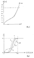
- Figure 1 is the typical wear profile (wear progress curve) of a hob.
- the wear is determined by the wear mark width VB measured on the hob. typically, the wear develops after a short running-in phase up to approx 80 ⁇ m almost proportional and then disproportionate. In the There is a phase of disproportionate wear progress for the milling cutter the greatest risk of overload.
- the tool should therefore be resharpened by 150 ⁇ m at the latest.
- the end of the curve is indicated by the tool break as the wear limit marked "max”.
- the wear mark width course is idealized represented as an average of several measurement results and can even for tools of the same tool type more or less strong deviate from this idealized curve, but usually one proportional and one disproportionate wear progress phase are recognizable.
- FIG. 3 shows how one for four monitored process parameters the only common wear characteristic curve is derived.
- a process parameter are monitored: workpiece temperature T, motor current I, Structure-borne noise A and the force F on the workpiece bearing of the machine tool.
- the diagrams in the first line of FIG. 3 only show examples, how the process values of the aforementioned process parameters change over time.
- the process values increase from a starting value to a maximum value "max", which marks the wear limit, on.
- maximum value which marks the wear limit
- the process values of the individual process parameters Develop differently over time, that is, different process value curves form.
- dashed lines Typical wear progress curve VB illustrated by FIG. 1 is shown. It can be seen that the wear progress curve is not necessarily matches the respective process value curves.
- the wear progress curve and the associated process value curves are first obtained as an average from several identical tools. This means that the tools are used up to their wear limit "max" and during this time the wear is recorded from time to time based on the width of the wear mark as well as the current process values for the individual process parameters T, I, A, F. This results in the mean value curves shown in the first line of FIG. 3.
- the values T S , I S , A S , F S denote a process value for a sharp tool and the values T max , I max , A max , F max denote the respective process values for the wear limit of the tool.
- the process parameter "workpiece temperature” (T) is defined as the temperature difference of the workpiece before and after its processing, whereby the temperature is preferably recorded without contact, for example using a pyrometer.
- the process parameter "motor current” (I) is defined as the current difference of the no-load current and the current active current and is a measure of that Energy consumed in the gearing process. Process values for this Process parameters are only recorded when the hob is in full cut works because the active power increases continuously in the gate phase and falls off when the milling cutter emerges.
- the process parameters "temperature” (T) and “motor current” (I), in which essentially static quantities are recorded the process parameters "structure-borne noise” (A) and “force” (F) become dynamic detected. That is, structure-borne noise process values are called vibrations detected on the counter arm by means of an accelerometer. But also the force, which is a dynamic stretch on the counter arm noticeable is detected by a strain gauge. acceleration Strain gauges are designed as piezo elements.
- Both the structure-borne noise and the expansion vibrations form a field of superimposed inhomogeneous vibrations. From this vibration field only those become Filtered out vibrations that are characteristic of the hobbing process are. This means that it only becomes a spectral narrowband component considered, the center frequency of the cleat engagement frequency of the Gear hob or a harmonic multiple thereof, and over a set period of time e.g. of the full cut becomes the effective value (RMS value) of this spectral narrowband component averaged by the to get the current process value.
- RMS value effective value
- the cleat engagement frequency SF is therefore a system-inherent operating variable, which can be used to evaluate the vibration signals without any effort can be.
- the evaluation has proven to be particularly suitable of the spectral narrowband component, the center frequency of which corresponds to three times the cleat engagement frequency of the tool.
- the normalized time course of the process values is shown in FIG. 3 in the diagrams on the second line.
- the normalized value T N , I N , A N , F N for a "sharp" tool is 1 in each case, whereas the normalized values labeled max T , max I , max A , max F for a tool are different at the wear limit can, for example 1.2, 2.5, 1.4, 3.7.
- a standardized, currently measured process value can therefore always be specified as a percentage deviation from the armed state "1" (20%, 150%, 40%, 270%).
- the weighting of the process values and the subsequent derivation of a common wear characteristic value is done by fuzzy classification. This means that in order to be able to compare the currently determined process values of the different process parameters with one another, an individual wear characteristic value that is between 0 and 1 is first assigned to each process value.
- the individual wear characteristic value 0 is assigned to the process value determined for a sharp tool and the wear characteristic value 1 to the process value determined for a blunt tool.
- Intermediate process values are weighted according to a bell curve, as shown in Figure 3 in the small diagrams next to the arrows. These bell curves are referred to as membership functions ⁇ (T N ), ⁇ (I N ), ⁇ (A N ), ⁇ (F N ) of the fuzzy classification system. This means that a wear characteristic value is assigned to each process value, which lies on the respective bell curve.
- the membership function or bell curve is depending on the monitoring process parameters depending on their typical individual Process value curve set up individually, so that from the weighting resulting wear characteristic curves are identical and therefore comparable are. This is shown by way of example in FIG.
- the solid Line gives the membership function for a process parameter whose process values increase linearly with time, that is to say in FIG. 3 for example for the process values of process parameter I (motor current).
- the membership functions (bell curves) for the other process parameters T, A, F are shifted left or right accordingly, to do justice to the course of their individual process value curves.
- the smoothing method further provides that process values that deviate extremely from the mean, to a deviation of only 20% be limited in order to avoid that the wear characteristic curve bends due to extreme individual outliers. Act it is not an outlier, but remains the process value in question the limit is sufficient for a long time of the extreme value to a 20% deviation around the wear characteristic curve to let it rise noticeably.
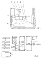
- a hobbing machine is shown schematically in FIG a workpiece 1 to be toothed on a workpiece carrier 5 by means of a counter holder 4 is fixed and with a drive 3 driven hob 2 is processed.
- the Sensors 6 and 7 can also be used at other locations on the hobbing machine, be arranged on the workpiece carrier 5, for example.
- the signals of the Body vibration sensor 6 and the strain sensor 7 are with an analog-to-digital converter over a short period of time of the full cut in which the hob 2 is in full engagement with the workpiece 1 is recorded and one not shown Measured value acquisition and processing device (data processing device), which will be explained below with reference to FIG. 5.
- the hobbing machine according to FIG. 4 has one Sensor for measuring the motor current and a pyrometer arrangement for contactless measurement of the workpiece temperature before and after Machining of the workpiece.
- the motor current and temperature sensors are not specifically shown in Figure 4.
- FIG. 5 shows schematically the components of the measured value acquisition and processing unit.
- the smoothed and normalized values are in a fuzzy classification first of all for each process parameter in the learning phase individually set membership function weighted to to get individual wear parameters between "0" and "1", the through suitable mathematical correlation to a common wear characteristic be summarized.
- the course of the common The machine operator is shown the wear value on a monitor Curve displayed. This common characteristic wear value also lies between the extremes "0” and “1", where "0" for a sharp and "1" stands for a blunt tool.
- the machine operator can then decide based on his own experience at which wear characteristic, for example at 0.5, he is the tool for resharpening exchanges.
Landscapes
- Engineering & Computer Science (AREA)
- Human Computer Interaction (AREA)
- Manufacturing & Machinery (AREA)
- Physics & Mathematics (AREA)
- General Physics & Mathematics (AREA)
- Automation & Control Theory (AREA)
- Length Measuring Devices With Unspecified Measuring Means (AREA)
- Machine Tool Sensing Apparatuses (AREA)
- Gear Processing (AREA)
- Numerical Control (AREA)
Abstract
Description
- Figur 1
- die zeitliche Entwicklung der Verschleißmarkenbreite VB an einem Wälzfräser,
- Figur 2
- unterschiedliche Zugehörigkeitsfunktionen zur Gewichtung der für verschiedene Prozeßparameter erfaßten Prozeßwerte,
- Figur 3
- die einzelnen Verfahrensschritte, um aus den für verschiedene Prozeßparameter erfaßten Prozeßwerten einen gemeinsamen aktuellen Verschleißkennwert abzuleiten,
- Figur 4
- schematisch eine Wälzfräsmaschine gemäß der vorliegenden Erfindung und
- Figur 5
- schematisch die Bestandteile einer Meßwertaquisitions und-verarbeitungseinheit.

Claims (41)
- Verfahren zur prozeßbegleitenden Verschleißerkennung an einem Verzahnungswerkzeug, umfassend die folgenden Schritte:Überwachen einer Gruppe von mindestens zwei Prozeßparametern eines Verzahnungsprozesses,Erfassen mindestens eines aktuellen Prozeßwertes zu jedem Prozeßparameter dieser Prozeßparametergruppe,Normieren der aktuell erfaßten Prozeßwerte, indem jeder aktuell erfaßte Prozeßwert zu einem Referenzprozeßwert in Beziehung gesetzt wird, der zu dem jeweils überwachten Prozeßparameter für ein scharfes Werkzeug erfaßt wurde,Gewichtung der normierten, aktuell erfaßten Prozeßwerte, um zu jedem überwachten Prozeßwert einen individuellen, aktuellen Verschleißkennwert zu erhalten, der auf den Werkzeugverschleiß schließen läßt,Ableiten eines gemeinsamen aktuellen Verschleißkennwertes für die Prozeßparametergruppe unter Verwendung der individuellen aktuellen Verschleißkennwerte.
- Verfahren nach Anspruch 1, gekennzeichnet durch den weiteren Schritt des Aufzeichnens der zeitlichen Entwicklung des gemeinsamen aktuellen Verschleißkennwertes als Verschleißkennwertkurve.
- Verfahren nach Anspruch 1 oder 2, gekennzeichnet durch den weiteren Schritt des Detektierens des Standzeitendes des Verzahnungswerkzeugs, wenn der gemeinsame aktuelle Verschleißwert jenseits einem vorgegebenen Schwellenwert liegt.
- Verfahren nach Anspruch 2, gekennzeichnet durch den weiteren Schritt des Detektierens des Standzeitendes anhand des Gradienten der Verschleißkennwertkurve.
- Verfahren nach einem der Ansprüche 1 bis 4, dadurch gekennzeichnet, daß die mindestens zwei überwachten Prozeßparameter ausgewählt sind aus der Gruppe folgender vier besonderer Prozeßparameter: Temperaturerwärmung, Körperschall, Dehnung von Bauteilen im Kraftfluß, Wirkleistung an der Werkzeugspindel.
- Verfahren nach Anspruch 5, dadurch gekennzeichnet, daß als einer der mindestens zwei Prozeßparameter die Temperaturerwärmung des Werkstücks als Differenz zwischen Werkstücktemperatur vor und nach der Bearbeitung überwacht wird.
- Verfahren nach Anspruch 5, dadurch gekennzeichnet, daß als einer der mindestens zwei Prozeßparameter die Wirkleistung an der Werkzeugspindel als Stromdifferenz aus dem aktuellen Wirkstrom und dem Leerlaufstrom überwacht wird.
- Verfahren nach Anspruch 5, dadurch gekennzeichnet, daß als einer der mindestens zwei Prozeßparameter der Körperschall als Schwingungen an der Werkzeuglagerung überwacht wird.
- Verfahren nach Anspruch 5, dadurch gekennzeichnet, daß als einer der mindestens zwei Prozeßparameter die Dehnung von Bauteilen im Kraftfluß als Dehnungsschwingungen an der Werkzeuglagerung überwacht wird.
- Verfahren nach einem der Ansprüche 8 oder 9, dadurch gekennzeichnet, daß das Verfahren die Verschleißerkennung an einem Fräswerkzeug betrifft und von den Körperschallschwingungen gemäß Anspruch 7 und/oder Dehnungsschwingungen gemäß Anspruch 8 ein oder mehrere spektrale Schmalbandanteile erfaßt werden, deren Mittenfrequenz der Stolleneingriffsfrequenz oder einem harmonischen Vielfachen der Stolleneingriffsfrequenz des Fräswerkzeugs entspricht.
- Verfahren nach Anspruch 10, dadurch gekennzeichnet, daß ein spektraler Schmalbandanteil erfaßt wird, dessen Mittenfrequenz der dreifachen Stolleneingriffsfrequenz des Verzahnungswerkzeugs entspricht.
- Verfahren nach einem der Ansprüche 10 oder 11, dadurch gekennzeichnet, daß das überwachte Fräswerkzeug ein Wälzfräser ist und die aktuellen Prozeßwerte zu den Prozeßparametern Körperschallschwingung gemäß Anspruch 7 und/oder Dehnungsschwingung gemäß Anspruch 8 und/oder Werkzeugspindelwirkleistung gemäß Anspruch 6 zu einem Zeitpunkt erfaßt wird, wenn sich der Wälzfräser in der Vollschnittphase befindet.
- Verfahren nach einem der Ansprüche 1 bis 9, dadurch gekennzeichnet, daß das Verfahren die Verschleißerkennung an einem Wälzschleifwerkzeug betrifft.
- Verfahren nach einem der Ansprüche 1 bis 13, dadurch gekennzeichnet, daß die Normierung des zu jedem Prozeßparameter erfaßten Prozeßwertes als prozentuale Abweichung zu dem zugehörigen Referenzprozeßwert für ein scharfes Werkzeug definiert ist.
- Verfahren nach einem der Ansprüche 1 bis 14, dadurch gekennzeichnet, daß die Gewichtung der normierten, aktuell erfaßten Prozeßwerte derart erfolgt, daß die individuellen aktuellen Verschleißkennwerte mit zunehmendem Werkzeugverschleiß ansteigen und der Anstieg in einem Bereich, der den Zeitpunkt der Notwendigkeit des Nachschärfens des Werkzeugs angibt, besonders steil ist.
- Verfahren nach Anspruch 15, dadurch gekennzeichnet, daß die Gewichtung der normierten, aktuell erfaßten Prozeßwerte mittels einer glockenförmigen Zugehörigkeitsfunktion erfolgt, deren maximale Steigung in den Bereich fällt, der den Zeitpunkt der Notwendigkeit des Nachschärfens des Werkzeugs angibt.
- Verfahren nach einem der Ansprüche 1 bis 16, dadurch gekennzeichnet, daß die Gewichtung der normierten, aktuell erfaßten Prozeßwerte zu individuellen aktuellen Verschleißkennwerten führt, die zwischen den Werten "0" für ein scharfes Werkzeug und "1" für ein stumpfes Werkzeug liegen.
- Verfahren nach einem der Ansprüche 1 bis 17, dadurch gekennzeichnet, daß die Gewichtung der normierten, aktuell erfaßten Prozeßwerte je nach überwachtem Prozeßparameter unterschiedlich erfolgt, so daß die jeweils erhaltenen individuellen, aktuellen Verschleißkennwerte unabhängig von dem überwachten Prozeßparameter in etwa übereinstimmen.
- Verfahren nach einem der Ansprüche 1 bis 18, dadurch gekennzeichnet, daß die Schritte des Gewichtens und Ableitens im Wege einer Fuzzy-Klassifikation erfolgen.
- Verfahren nach einem der Ansprüche 1 bis 19, dadurch gekennzeichnet, daß die Ableitung des gemeinsamen aktuellen Verschleißkennwertes fuzzy-logisch ermittelt wird aus den individuellen Verschleißkennwerten µ(m1) bis µ(mk) der überwachten Prozeßparameter m1 bis mk gemäß folgender Formel:

- Verfahren gemäß Anspruch 1, dadurch gekennzeichnet, daß die Schritte des Gewichtens und Ableitens mittels neuronalen Netzen durchgeführt werden.
- Verfahren nach einem der Ansprüche 1 bis 21, dadurch gekennzeichnet, daß die aktuell erfaßten Prozeßwerte vor ihrer Normierung durch Mittelwertbildung mit zuvor für denselben Prozeßparameter ermittelten Prozeßwerten geglättet wird.
- Verfahren nach Anspruch 22, dadurch gekennzeichnet, daß im Falle der Überwachung eines Wälzfräswerkzeugs zur Mittelwertbildung die über eine gesamte vorangegangene Shiftperiode erfaßten Prozeßwerte berücksichtigt werden.
- Verzahnungsvorrichtung, die einen Antrieb (3) für ein Verzahnungswerkzeug (2), eine Werkstückaufnahme (4, 5) zur Fixierung eines Werkstücks (1) und eine Werkzeugverschleißüberwachungseinrichtung umfaßt, wobei die Werkzeugverschleißüberwachungsvorrichtung Sensoren (6, 7) zum Erfassen von aktuellen Prozeßwerten zu mindestens zwei unterschiedlichen zu überwachenden Prozeßparametern eines Verzahnungsprozesses und desweiteren eine Datenverarbeitungseinrichtung aufweist, mit Mitteln zum Normieren der von den Sensoren jeweils aktuell erfaßten Prozeßwerte, indem jeder aktuell erfaßte Prozeßwert zu einem Referenzprozeßwert in Beziehung gesetzt wird, der zu dem jeweils überwachten Prozeßparameter für ein scharfes Werkzeug erfaßt wurde, und mit Mitteln zum Gewichten der so normierten, aktuell erfaßten Prozeßwerte, so daß zu jedem überwachten Prozeßparameter ein individueller, aktueller Verschleißkennwert erhalten wird, der auf den Werkzeugverschleiß schließen läßt, und mit Mitteln zum Ableiten eines gemeinsamen aktuellen Verschleißkennwerts für die Prozeßparametergruppe aus den so erhaltenen individuellen aktuellen Verschleißkennwerten.
- Verzahnungsvorrichtung nach Anspruch 24, gekennzeichnet durch eine Anzeigeneinrichtung, mit der die zeitliche Entwicklung des gemeinsamen aktuellen Verschleißkennwertes als Verschleißkennwertkurve angezeigt wird.
- Verzahnungsvorrichtung nach einem der Ansprüche 24 oder 25, dadurch gekennzeichnet, daß die mindestens zwei überwachten Prozeßparameter ausgewählt sind aus der Gruppe folgender vier besonderer Prozeßparameter: Temperaturerwärmung, Körperschall, Dehnung von Bauteilen im Kraftfluß, Wirkleistung an der Werkzeugspindel.
- Verzahnungsvorrichtung nach Anspruch 26, gekennzeichnet durch Sensoren zum Erfassen der Temperaturerwärmung des Werkstücks als Differenz zwischen Werkstücktemperatur vor und nach dessen Bearbeitung.
- Verzahnungsvorrichtung nach Anspruch 26, gekennzeichnet durch eine Einrichtung zum Erfassen der Wirkleistung an der Werkzeugspindel als Stromdifferenz aus dem aktuellen Wirkstrom und dem Leerlaufstrom.
- Verzahnungsvorrichtung nach Anspruch 26, gekennzeichnet durch Sensoren zum Erfassen des Körperschalls als Schwingungen an der Werkstücklagerung.
- Verzahnungsvorrichtung nach Anspruch 26, gekennzeichnet durch Sensoren zum Erfassen der Dehnung von Bauteilen im Kraftfluß als Dehnungsschwingungen an der Werkstücklagerung.
- Verzahnungsvorrichtung nach einem der Ansprüche 29 oder 30, dadurch gekennzeichnet, daß die Verzahnungsvorrichtung eine Fräsmaschine ist und daß ein Schmalbandfilter vorgesehen ist, um aus den erfaßten Körperschallschwingungen gemäß Anspruch 28 und/oder Dehnungsschwingungen gemäß Anspruch 29 lediglich ein oder mehrere spektrale Schmalbandanteile auszufiltern, deren Mittenfrequenz der Stolleneingriffsfrequenz oder einem harmonischen Vielfachen der Stolleneingriffsfrequenz des Fräswerkzeugs entspricht.
- Verzahnungsvorrichtung nach Anspruch 31, dadurch gekennzeichnet, daß der Schmalbandfilter einen spektralen Schmalbandanteil ausfiltert, dessen Mittenfrequenz der dreifachen Stolleneingriffsfrequenz des Fräswerkzeugs entspricht.
- Verzahnungsvorrichtung nach einem der Ansprüche 31 oder 32, dadurch gekennzeichnet, daß die Fräsmaschine eine Wälzfräsmaschine ist und eine Steuerung vorgesehen ist, um die aktuellen Prozeßwerte zu den Prozeßparametern Körperschall gemäß Anspruch 28 und/oder Dehnung gemäß Anspruch 29 und/oder Werkzeugspindelwirkleistung gemäß Anspruch 27 zu einem Zeitpunkt zu erfassen, wenn sich der Wälzfräser in der Vollschnittphase befindet.
- Verzahnungsvorrichtung nach einem der Ansprüche 24 bis 30, dadurch gekennzeichnet, daß die Verzahnungsvorrichtung eine Wälzschleifmaschine ist.
- Verzahnungsvorrichtung nach einem der Ansprüche 24 bis 34, dadurch gekennzeichnet, daß die Mittel zum Gewichten der normierten, aktuell erfaßten Prozeßwerte individuelle aktuelle Verschleißkennwerte zur Verfügung stellen, die mit zunehmendem Werkzeugverschleiß ansteigen, wobei der Anstieg in einem Bereich, der den Zeitpunkt der Notwendigkeit des Nachschärfens des Werkzeugs angibt, besonders steil ist.
- Verzahnungsvorrichtung nach Anspruch 35, dadurch gekennzeichnet, daß die Mittel zum Gewichten der normierten, aktuell erfaßten Prozeßwerte eine Verknüpfung der Prozeßwerte mit einer glockenförmigen Zugehörigkeitsfunktion durchführen, welche in der Datenverarbeitungseinrichtung gespeichert ist.
- Verzahnungsvorrichtung nach einem der Ansprüche 24 bis 36, dadurch gekennzeichnet, daß die Mittel zum Gewichten der normierten, aktuell erfaßten Prozeßwerte individuelle aktuelle Verschleißkennwerte zur Verfügung stellen, die zwischen den Werten "0" für ein scharfes Werkzeug und "1" für ein stumpfes Werkzeug liegen.
- Verzahnungsvorrichtung nach einem der Ansprüche 36 oder 37, dadurch gekennzeichnet, daß die Mittel zum Gewichten der normierten, aktuell erfaßten Prozeßwerte je nach überwachtem Prozeßparameter eine Verknüpfung mit unterschiedlichen Zugehörigkeitsfunktionen durchführt, so daß die jeweils erhaltenen individuellen, aktuellen Verschleißkennwerte unabhängig von dem überwachten Prozeßparameter in etwa übereinstimmen.
- Verzahnungsvorrichtung nach einem der Ansprüche 24 bis 37, dadurch gekennzeichnet, daß die Mittel zum Gewichten und Ableiten als Fuzzy-Klassifikationssystem ausgebildet sind.
- Verzahnungsvorrichtung gemäß Anspruch 24, dadurch gekennzeichnet, daß die Mittel zum Gewichten und Ableiten neuronale Netze umfassen.
- Verzahnungsvorrichtung nach einem der Ansprüche 24 bis 40, gekennzeichnet durch Mittel zum Glätten der aktuell erfaßten Prozeßwerte vor ihrer Normierung durch Mittelwertbildung mit zuvor für denselben Prozeßparameter ermittelten Prozeßwerten.
Priority Applications (3)
| Application Number | Priority Date | Filing Date | Title |
|---|---|---|---|
| AT00121046T ATE261592T1 (de) | 2000-09-27 | 2000-09-27 | Prozessüberwachung zur verschleisserkennung an verzahnungswerkzeugen |
| DE50005606T DE50005606D1 (de) | 2000-09-27 | 2000-09-27 | Prozessüberwachung zur Verschleisserkennung an Verzahnungswerkzeugen |
| EP00121046A EP1195668B1 (de) | 2000-09-27 | 2000-09-27 | Prozessüberwachung zur Verschleisserkennung an Verzahnungswerkzeugen |
Applications Claiming Priority (1)
| Application Number | Priority Date | Filing Date | Title |
|---|---|---|---|
| EP00121046A EP1195668B1 (de) | 2000-09-27 | 2000-09-27 | Prozessüberwachung zur Verschleisserkennung an Verzahnungswerkzeugen |
Publications (2)
| Publication Number | Publication Date |
|---|---|
| EP1195668A1 true EP1195668A1 (de) | 2002-04-10 |
| EP1195668B1 EP1195668B1 (de) | 2004-03-10 |
Family
ID=8169961
Family Applications (1)
| Application Number | Title | Priority Date | Filing Date |
|---|---|---|---|
| EP00121046A Expired - Lifetime EP1195668B1 (de) | 2000-09-27 | 2000-09-27 | Prozessüberwachung zur Verschleisserkennung an Verzahnungswerkzeugen |
Country Status (3)
| Country | Link |
|---|---|
| EP (1) | EP1195668B1 (de) |
| AT (1) | ATE261592T1 (de) |
| DE (1) | DE50005606D1 (de) |
Cited By (23)
| Publication number | Priority date | Publication date | Assignee | Title |
|---|---|---|---|---|
| EP1607192A3 (de) * | 2004-06-15 | 2008-12-31 | ABB PATENT GmbH | Verfahren und System zur Verschleissabschätzung von Achsen eines Roboterarmes |
| EP2103378A1 (de) * | 2008-03-18 | 2009-09-23 | Klingelnberg AG | Werkzeugverschleiss in Bearbeitungsmaschinen |
| CN108279121A (zh) * | 2018-02-08 | 2018-07-13 | 湘潭大学 | 一种大切深下滚刀刃底接触力特性测试系统及其测试方法 |
| CN109191367A (zh) * | 2018-08-02 | 2019-01-11 | 哈尔滨理工大学 | 刀具磨损图像的拼接方法及刀具的寿命预测方法 |
| US10322487B1 (en) | 2016-07-15 | 2019-06-18 | Pearson Incorporated | Roller mill grinding apparatus with regenerative capability |
| US10751722B1 (en) | 2018-10-24 | 2020-08-25 | Pearson Incorporated | System for processing cannabis crop materials |
| US10757860B1 (en) | 2019-10-31 | 2020-09-01 | Hemp Processing Solutions, LLC | Stripper apparatus crop harvesting system |
| CN111626623A (zh) * | 2020-05-29 | 2020-09-04 | 中铁二十局集团第五工程有限公司 | 一种复合地层中盾构机滚刀换刀控制方法 |
| DE102016011532B4 (de) * | 2015-09-30 | 2020-09-10 | Fanuc Corporation | Maschinenlernvorrichtung und Maschinenlernverfahren zum Optimieren der Häufigkeit einer Werkzeugkorrektur einer Werkzeugmaschine und Werkzeugmaschine mit der Maschinenlernvorrichtung |
| US10785906B2 (en) | 2019-02-19 | 2020-09-29 | Pearson Incorporated | Plant processing system |
| US10807098B1 (en) | 2017-07-26 | 2020-10-20 | Pearson Incorporated | Systems and methods for step grinding |
| WO2020212123A1 (de) * | 2019-04-15 | 2020-10-22 | Gleason-Pfauter Maschinenfabrik Gmbh | Verfahren des erzeugens oder bearbeitens einer verzahnung |
| US10913071B2 (en) | 2016-03-09 | 2021-02-09 | Pearson Incorporated | Scalper apparatus and processing system |
| US10933424B1 (en) | 2019-12-11 | 2021-03-02 | Pearson Incorporated | Grinding roll improvements |
| US20210178499A1 (en) * | 2017-12-22 | 2021-06-17 | Gleason-Pfauter Maschinenfabrik Gmbh | Method for machining toothings, as well as toothing machine and control program for same |
| CN113155435A (zh) * | 2021-04-30 | 2021-07-23 | 深圳素士科技股份有限公司 | 陶瓷刀片检测方法、剃须刀检测装置和剃须刀 |
| CN114326593A (zh) * | 2021-12-16 | 2022-04-12 | 成都航天科工大数据研究院有限公司 | 一种刀具寿命预测系统及方法 |
| US11325133B1 (en) | 2018-07-26 | 2022-05-10 | Pearson Incorporated | Systems and methods for monitoring the roll diameter and shock loads in a milling apparatus |
| CN114559297A (zh) * | 2020-11-27 | 2022-05-31 | 财团法人工业技术研究院 | 刀具状态评估系统及方法 |
| WO2022100972A3 (de) * | 2020-11-12 | 2022-08-11 | KAPP NILES GmbH & Co. KG | Verfahren zum schleifen einer verzahnung oder eines profils eines werkstücks |
| CN115730856A (zh) * | 2022-11-29 | 2023-03-03 | 中国电子产品可靠性与环境试验研究所((工业和信息化部电子第五研究所)(中国赛宝实验室)) | 防护涂层环境适应性定量综合评价方法、装置和设备 |
| CN117681051A (zh) * | 2023-12-26 | 2024-03-12 | 江苏科技大学 | 一种立铣刀非均匀磨损在线识别方法 |
| CN117697533A (zh) * | 2023-11-22 | 2024-03-15 | 大连理工大学 | 一种基于长短时记忆神经网络-机理混合驱动的刀具磨损在线监测方法 |
Citations (8)
| Publication number | Priority date | Publication date | Assignee | Title |
|---|---|---|---|---|
| US4514797A (en) * | 1982-09-03 | 1985-04-30 | Gte Valeron Corporation | Worn tool detector utilizing normalized vibration signals |
| US4849741A (en) * | 1988-01-13 | 1989-07-18 | General Electric Company | Tool break detecting method and system preventing false alarms due to rough surfaces |
| EP0336477A1 (de) * | 1988-04-05 | 1989-10-11 | Services Petroliers Schlumberger | Verfahren zum Anzeigen von Bohrmeissel-Verschleiss |
| EP0442020A1 (de) * | 1988-03-21 | 1991-08-21 | Monitoring Technology Corporation | Methode und Anlage zur Feststellung von Defekten am Getriebe |
| US5243533A (en) * | 1990-03-26 | 1993-09-07 | Ntn Corporation | Tool abnormality detecting device |
| US5266929A (en) * | 1992-05-26 | 1993-11-30 | General Electric Company | Metal cutting tool wear indicator method and system |
| US5319357A (en) * | 1992-06-08 | 1994-06-07 | General Electric Company | Metal cutting tool failure event sensor |
| WO1997025659A1 (en) * | 1993-12-27 | 1997-07-17 | Omat Ltd. | Automatic monitoring of tool status |
-
2000
- 2000-09-27 DE DE50005606T patent/DE50005606D1/de not_active Expired - Lifetime
- 2000-09-27 AT AT00121046T patent/ATE261592T1/de not_active IP Right Cessation
- 2000-09-27 EP EP00121046A patent/EP1195668B1/de not_active Expired - Lifetime
Patent Citations (8)
| Publication number | Priority date | Publication date | Assignee | Title |
|---|---|---|---|---|
| US4514797A (en) * | 1982-09-03 | 1985-04-30 | Gte Valeron Corporation | Worn tool detector utilizing normalized vibration signals |
| US4849741A (en) * | 1988-01-13 | 1989-07-18 | General Electric Company | Tool break detecting method and system preventing false alarms due to rough surfaces |
| EP0442020A1 (de) * | 1988-03-21 | 1991-08-21 | Monitoring Technology Corporation | Methode und Anlage zur Feststellung von Defekten am Getriebe |
| EP0336477A1 (de) * | 1988-04-05 | 1989-10-11 | Services Petroliers Schlumberger | Verfahren zum Anzeigen von Bohrmeissel-Verschleiss |
| US5243533A (en) * | 1990-03-26 | 1993-09-07 | Ntn Corporation | Tool abnormality detecting device |
| US5266929A (en) * | 1992-05-26 | 1993-11-30 | General Electric Company | Metal cutting tool wear indicator method and system |
| US5319357A (en) * | 1992-06-08 | 1994-06-07 | General Electric Company | Metal cutting tool failure event sensor |
| WO1997025659A1 (en) * | 1993-12-27 | 1997-07-17 | Omat Ltd. | Automatic monitoring of tool status |
Cited By (37)
| Publication number | Priority date | Publication date | Assignee | Title |
|---|---|---|---|---|
| EP1607192A3 (de) * | 2004-06-15 | 2008-12-31 | ABB PATENT GmbH | Verfahren und System zur Verschleissabschätzung von Achsen eines Roboterarmes |
| EP2103378A1 (de) * | 2008-03-18 | 2009-09-23 | Klingelnberg AG | Werkzeugverschleiss in Bearbeitungsmaschinen |
| DE102016011532B4 (de) * | 2015-09-30 | 2020-09-10 | Fanuc Corporation | Maschinenlernvorrichtung und Maschinenlernverfahren zum Optimieren der Häufigkeit einer Werkzeugkorrektur einer Werkzeugmaschine und Werkzeugmaschine mit der Maschinenlernvorrichtung |
| US10913071B2 (en) | 2016-03-09 | 2021-02-09 | Pearson Incorporated | Scalper apparatus and processing system |
| US10322487B1 (en) | 2016-07-15 | 2019-06-18 | Pearson Incorporated | Roller mill grinding apparatus with regenerative capability |
| US11534770B1 (en) | 2017-07-26 | 2022-12-27 | Pearson Incorporated | Systems and methods for step grinding |
| US10807098B1 (en) | 2017-07-26 | 2020-10-20 | Pearson Incorporated | Systems and methods for step grinding |
| US20210178499A1 (en) * | 2017-12-22 | 2021-06-17 | Gleason-Pfauter Maschinenfabrik Gmbh | Method for machining toothings, as well as toothing machine and control program for same |
| CN108279121B (zh) * | 2018-02-08 | 2023-10-13 | 中铁山河工程装备股份有限公司 | 一种大切深下滚刀刃底接触力特性测试系统及其测试方法 |
| CN108279121A (zh) * | 2018-02-08 | 2018-07-13 | 湘潭大学 | 一种大切深下滚刀刃底接触力特性测试系统及其测试方法 |
| US11325133B1 (en) | 2018-07-26 | 2022-05-10 | Pearson Incorporated | Systems and methods for monitoring the roll diameter and shock loads in a milling apparatus |
| CN109191367B (zh) * | 2018-08-02 | 2023-06-16 | 哈尔滨理工大学 | 刀具磨损图像的拼接方法及刀具的寿命预测方法 |
| CN109191367A (zh) * | 2018-08-02 | 2019-01-11 | 哈尔滨理工大学 | 刀具磨损图像的拼接方法及刀具的寿命预测方法 |
| US10751722B1 (en) | 2018-10-24 | 2020-08-25 | Pearson Incorporated | System for processing cannabis crop materials |
| US10785906B2 (en) | 2019-02-19 | 2020-09-29 | Pearson Incorporated | Plant processing system |
| US20220168831A1 (en) * | 2019-04-15 | 2022-06-02 | Gleason-Pfauter Maschinenfabrik Gmbh | Method for producing or machining toothing |
| US12472569B2 (en) * | 2019-04-15 | 2025-11-18 | Gleason-Pfauter Maschinenfabrik Gmbh | Method for producing or machining toothing |
| CN113631311A (zh) * | 2019-04-15 | 2021-11-09 | 格里森-普法特机械制造有限公司 | 生产或加工齿部的方法 |
| CN113631311B (zh) * | 2019-04-15 | 2024-11-12 | 格里森-普法特机械制造有限公司 | 生产齿部的方法、齿轮切削机床和监控程序 |
| WO2020212123A1 (de) * | 2019-04-15 | 2020-10-22 | Gleason-Pfauter Maschinenfabrik Gmbh | Verfahren des erzeugens oder bearbeitens einer verzahnung |
| JP2022529951A (ja) * | 2019-04-15 | 2022-06-27 | グリーソン - プァウター マシネンファブリク ゲーエムベーハー | 歯部の製作または機械加工のための方法 |
| US10757860B1 (en) | 2019-10-31 | 2020-09-01 | Hemp Processing Solutions, LLC | Stripper apparatus crop harvesting system |
| US11751507B1 (en) | 2019-10-31 | 2023-09-12 | Hemp Processing Solutions, LLC | Crop harvesting system with plant stripping apparatus |
| US10933424B1 (en) | 2019-12-11 | 2021-03-02 | Pearson Incorporated | Grinding roll improvements |
| US11826762B1 (en) | 2019-12-11 | 2023-11-28 | Pearson Incorporated | Grinding roll improvements |
| US11077445B2 (en) | 2019-12-11 | 2021-08-03 | Pearson Incorporated | Grinding roll improvements |
| CN111626623A (zh) * | 2020-05-29 | 2020-09-04 | 中铁二十局集团第五工程有限公司 | 一种复合地层中盾构机滚刀换刀控制方法 |
| CN111626623B (zh) * | 2020-05-29 | 2022-05-24 | 中铁二十局集团第五工程有限公司 | 一种复合地层中盾构机滚刀换刀控制方法 |
| WO2022100972A3 (de) * | 2020-11-12 | 2022-08-11 | KAPP NILES GmbH & Co. KG | Verfahren zum schleifen einer verzahnung oder eines profils eines werkstücks |
| CN114559297A (zh) * | 2020-11-27 | 2022-05-31 | 财团法人工业技术研究院 | 刀具状态评估系统及方法 |
| CN114559297B (zh) * | 2020-11-27 | 2023-09-19 | 财团法人工业技术研究院 | 刀具状态评估系统及方法 |
| CN113155435A (zh) * | 2021-04-30 | 2021-07-23 | 深圳素士科技股份有限公司 | 陶瓷刀片检测方法、剃须刀检测装置和剃须刀 |
| CN114326593B (zh) * | 2021-12-16 | 2024-05-03 | 成都航天科工大数据研究院有限公司 | 一种刀具寿命预测系统及方法 |
| CN114326593A (zh) * | 2021-12-16 | 2022-04-12 | 成都航天科工大数据研究院有限公司 | 一种刀具寿命预测系统及方法 |
| CN115730856A (zh) * | 2022-11-29 | 2023-03-03 | 中国电子产品可靠性与环境试验研究所((工业和信息化部电子第五研究所)(中国赛宝实验室)) | 防护涂层环境适应性定量综合评价方法、装置和设备 |
| CN117697533A (zh) * | 2023-11-22 | 2024-03-15 | 大连理工大学 | 一种基于长短时记忆神经网络-机理混合驱动的刀具磨损在线监测方法 |
| CN117681051A (zh) * | 2023-12-26 | 2024-03-12 | 江苏科技大学 | 一种立铣刀非均匀磨损在线识别方法 |
Also Published As
| Publication number | Publication date |
|---|---|
| ATE261592T1 (de) | 2004-03-15 |
| DE50005606D1 (de) | 2004-04-15 |
| EP1195668B1 (de) | 2004-03-10 |
Similar Documents
| Publication | Publication Date | Title |
|---|---|---|
| EP1195668B1 (de) | Prozessüberwachung zur Verschleisserkennung an Verzahnungswerkzeugen | |
| DE60310661T2 (de) | Vorrichtung zur Überwachung oder Vermeidung eines Werkzeugbruchs | |
| EP1259941B1 (de) | Verfahren und vorrichtung zur ermittlung der verbleibenden betriebsdauer eines produktes | |
| EP3792712A1 (de) | Verfahren zur korrektur von werkzeugparametern einer werkzeugmaschine zur bearbeitung von werkstücken | |
| DE3331793A1 (de) | Einrichtung zum feststellen von werkzeugabnutzung | |
| EP4100803B1 (de) | Verfahren und vorrichtung zum betrieb einer maschine mit einem werkzeug | |
| EP1397274B1 (de) | Verfahren zur festlegung von zeitpunkt und umfang von wartungsvorgängen | |
| EP3403150B1 (de) | Verfahren zum überwachen einer werkzeugmaschine und steuerung | |
| EP1607192B1 (de) | Verfahren und System zur Verschleissabschätzung von Achsen eines Roboterarmes | |
| EP3679433B1 (de) | Verfahren zum überwachen einer werkzeugmaschine, insbesondere auf werkzeugbruch | |
| DE102016002995B3 (de) | Verfahren zur Überwachung eines Antriebssytems einer Werkzeugmaschine | |
| DE10348608B4 (de) | Überwachungssystem und Verfahren für eine Spindel | |
| EP0756219A2 (de) | Verfahren zur Überwachung von Produkteigenschaften und Verfahren zur Regelung eines Herstellungs-prozesses | |
| DE102017009046A1 (de) | Zustandsüberwachungssystem, verfahren zum bestimmen eines abnutzungsgrads, wartungssteuerungsverfahren, betriebsführungs- und sicherheitssystem und extruder | |
| AT525762A2 (de) | Echtzeit-Überwachungsverfahren und Stabilitätsanalyseverfahren für ein Stranggießverfahren | |
| DE102016005214A1 (de) | Vorrichtung zum Überprüfen eines Zustandes eines Maschinenteils | |
| EP3081914A1 (de) | Überwachung einer Maschine mit einer Rotierenden Maschinenkomponente | |
| DE102010010743B4 (de) | Umformmaschine zur Herstellung von Formteilen | |
| EP3056957A1 (de) | Diagnoseeinrichtung und -verfahren zur Überwachung des Betriebs eines Regelkreises | |
| DE102020205895A1 (de) | Verfahren sowie Vorrichtung zur automatischen Überwachung eines zyklischen Prozesses | |
| EP4244011B1 (de) | Verfahren zum schleifen einer verzahnung oder eines profils eines werkstücks | |
| DE3136434A1 (de) | Verfahren zur ueberwachung der standzeit von werkzeugen | |
| DE102010009164A1 (de) | Verfahren und Vorrichtung zum Steuern einer Textilmaschine oder eines angetriebenen Teils einer Textilmaschine | |
| EP1711283B1 (de) | Regelverfahren und regler für ein walzgerüst | |
| EP3956094B1 (de) | Verfahren des erzeugens oder bearbeitens einer verzahnung |
Legal Events
| Date | Code | Title | Description |
|---|---|---|---|
| PUAI | Public reference made under article 153(3) epc to a published international application that has entered the european phase |
Free format text: ORIGINAL CODE: 0009012 |
|
| 17P | Request for examination filed |
Effective date: 20010914 |
|
| AK | Designated contracting states |
Kind code of ref document: A1 Designated state(s): AT BE CH CY DE DK ES FI FR GB GR IE IT LI LU MC NL PT SE |
|
| AX | Request for extension of the european patent |
Free format text: AL;LT;LV;MK;RO;SI |
|
| AKX | Designation fees paid |
Free format text: AT BE CH CY DE DK ES FI FR GB GR IE IT LI LU MC NL PT SE |
|
| REG | Reference to a national code |
Ref country code: GB Ref legal event code: FG4D Free format text: NOT ENGLISH |
|
| GRAP | Despatch of communication of intention to grant a patent |
Free format text: ORIGINAL CODE: EPIDOSNIGR1 |
|
| RAP1 | Party data changed (applicant data changed or rights of an application transferred) |
Owner name: FRAUNHOFER-GESELLSCHAFT ZUR FOERDERUNG DERANGEWAND Owner name: LIEBHERR-VERZAHNTECHNIK GMBH |
|
| GRAS | Grant fee paid |
Free format text: ORIGINAL CODE: EPIDOSNIGR3 |
|
| GRAA | (expected) grant |
Free format text: ORIGINAL CODE: 0009210 |
|
| AK | Designated contracting states |
Kind code of ref document: B1 Designated state(s): AT BE CH CY DE DK ES FI FR GB GR IE IT LI LU MC NL PT SE |
|
| PG25 | Lapsed in a contracting state [announced via postgrant information from national office to epo] |
Ref country code: IT Free format text: LAPSE BECAUSE OF FAILURE TO SUBMIT A TRANSLATION OF THE DESCRIPTION OR TO PAY THE FEE WITHIN THE PRESCRIBED TIME-LIMIT;WARNING: LAPSES OF ITALIAN PATENTS WITH EFFECTIVE DATE BEFORE 2007 MAY HAVE OCCURRED AT ANY TIME BEFORE 2007. THE CORRECT EFFECTIVE DATE MAY BE DIFFERENT FROM THE ONE RECORDED. Effective date: 20040310 Ref country code: FI Free format text: LAPSE BECAUSE OF FAILURE TO SUBMIT A TRANSLATION OF THE DESCRIPTION OR TO PAY THE FEE WITHIN THE PRESCRIBED TIME-LIMIT Effective date: 20040310 Ref country code: IE Free format text: LAPSE BECAUSE OF FAILURE TO SUBMIT A TRANSLATION OF THE DESCRIPTION OR TO PAY THE FEE WITHIN THE PRESCRIBED TIME-LIMIT Effective date: 20040310 Ref country code: FR Free format text: LAPSE BECAUSE OF FAILURE TO SUBMIT A TRANSLATION OF THE DESCRIPTION OR TO PAY THE FEE WITHIN THE PRESCRIBED TIME-LIMIT Effective date: 20040310 Ref country code: NL Free format text: LAPSE BECAUSE OF FAILURE TO SUBMIT A TRANSLATION OF THE DESCRIPTION OR TO PAY THE FEE WITHIN THE PRESCRIBED TIME-LIMIT Effective date: 20040310 Ref country code: CY Free format text: LAPSE BECAUSE OF FAILURE TO SUBMIT A TRANSLATION OF THE DESCRIPTION OR TO PAY THE FEE WITHIN THE PRESCRIBED TIME-LIMIT Effective date: 20040310 Ref country code: GB Free format text: LAPSE BECAUSE OF FAILURE TO SUBMIT A TRANSLATION OF THE DESCRIPTION OR TO PAY THE FEE WITHIN THE PRESCRIBED TIME-LIMIT Effective date: 20040310 |
|
| REG | Reference to a national code |
Ref country code: CH Ref legal event code: EP |
|
| REG | Reference to a national code |
Ref country code: IE Ref legal event code: FG4D Free format text: GERMAN |
|
| REF | Corresponds to: |
Ref document number: 50005606 Country of ref document: DE Date of ref document: 20040415 Kind code of ref document: P |
|
| PG25 | Lapsed in a contracting state [announced via postgrant information from national office to epo] |
Ref country code: GR Free format text: LAPSE BECAUSE OF FAILURE TO SUBMIT A TRANSLATION OF THE DESCRIPTION OR TO PAY THE FEE WITHIN THE PRESCRIBED TIME-LIMIT Effective date: 20040610 Ref country code: DK Free format text: LAPSE BECAUSE OF FAILURE TO SUBMIT A TRANSLATION OF THE DESCRIPTION OR TO PAY THE FEE WITHIN THE PRESCRIBED TIME-LIMIT Effective date: 20040610 Ref country code: SE Free format text: LAPSE BECAUSE OF FAILURE TO SUBMIT A TRANSLATION OF THE DESCRIPTION OR TO PAY THE FEE WITHIN THE PRESCRIBED TIME-LIMIT Effective date: 20040610 |
|
| PG25 | Lapsed in a contracting state [announced via postgrant information from national office to epo] |
Ref country code: ES Free format text: LAPSE BECAUSE OF FAILURE TO SUBMIT A TRANSLATION OF THE DESCRIPTION OR TO PAY THE FEE WITHIN THE PRESCRIBED TIME-LIMIT Effective date: 20040621 |
|
| NLV1 | Nl: lapsed or annulled due to failure to fulfill the requirements of art. 29p and 29m of the patents act | ||
| GBV | Gb: ep patent (uk) treated as always having been void in accordance with gb section 77(7)/1977 [no translation filed] |
Effective date: 20040310 |
|
| PG25 | Lapsed in a contracting state [announced via postgrant information from national office to epo] |
Ref country code: LU Free format text: LAPSE BECAUSE OF NON-PAYMENT OF DUE FEES Effective date: 20040927 Ref country code: AT Free format text: LAPSE BECAUSE OF NON-PAYMENT OF DUE FEES Effective date: 20040927 |
|
| PG25 | Lapsed in a contracting state [announced via postgrant information from national office to epo] |
Ref country code: MC Free format text: LAPSE BECAUSE OF NON-PAYMENT OF DUE FEES Effective date: 20040930 Ref country code: CH Free format text: LAPSE BECAUSE OF NON-PAYMENT OF DUE FEES Effective date: 20040930 Ref country code: BE Free format text: LAPSE BECAUSE OF NON-PAYMENT OF DUE FEES Effective date: 20040930 Ref country code: LI Free format text: LAPSE BECAUSE OF NON-PAYMENT OF DUE FEES Effective date: 20040930 |
|
| REG | Reference to a national code |
Ref country code: IE Ref legal event code: FD4D |
|
| PLBE | No opposition filed within time limit |
Free format text: ORIGINAL CODE: 0009261 |
|
| STAA | Information on the status of an ep patent application or granted ep patent |
Free format text: STATUS: NO OPPOSITION FILED WITHIN TIME LIMIT |
|
| EN | Fr: translation not filed | ||
| 26N | No opposition filed |
Effective date: 20041213 |
|
| BERE | Be: lapsed |
Owner name: *LIEBHERR-VERZAHNTECHNIK G.M.B.H. Effective date: 20040930 Owner name: *FRAUNHOFER-GESELLSCHAFT ZUR FORDERUNG DER ANGEWAN Effective date: 20040930 |
|
| REG | Reference to a national code |
Ref country code: CH Ref legal event code: PL |
|
| BERE | Be: lapsed |
Owner name: *FRAUNHOFER-GESELLSCHAFT ZUR FORDERUNG DER ANGEWAN Effective date: 20040930 Owner name: *LIEBHERR-VERZAHNTECHNIK G.M.B.H. Effective date: 20040930 |
|
| PG25 | Lapsed in a contracting state [announced via postgrant information from national office to epo] |
Ref country code: PT Free format text: LAPSE BECAUSE OF NON-PAYMENT OF DUE FEES Effective date: 20040810 |
|
| PGFP | Annual fee paid to national office [announced via postgrant information from national office to epo] |
Ref country code: DE Payment date: 20130930 Year of fee payment: 14 |
|
| REG | Reference to a national code |
Ref country code: DE Ref legal event code: R119 Ref document number: 50005606 Country of ref document: DE |
|
| REG | Reference to a national code |
Ref country code: DE Ref legal event code: R119 Ref document number: 50005606 Country of ref document: DE Effective date: 20150401 |
|
| PG25 | Lapsed in a contracting state [announced via postgrant information from national office to epo] |
Ref country code: DE Free format text: LAPSE BECAUSE OF NON-PAYMENT OF DUE FEES Effective date: 20150401 |