Field of the Invention
-
This invention relates in general to electrostatographic imaging and, more particularly, to
fusing stations and rollers useful for color imaging having a stiffening layer included within
an internally-heated, compliant toner fuser rollers used with a compliant pressure rollers.
Background of the Invention
-
In electrostatographic imaging and recording processes such as electrophotographic
reproduction, an electrostatic latent image is formed on a primary image-forming member
such as a photoconductive surface and is developed with a thermoplastic toner powder to
form a toner image. The toner image is thereafter transferred to a receiver, e.g., a sheet of
paper or plastic, and the toner image is subsequently fused to the receiver in a fusing
station using heat or pressure, or both heat and pressure. The fuser member can be a
roller, belt, or any surface having a suitable shape for fixing thermoplastic toner powder to
the receiver. The fusing step in a roller fuser commonly consists of passing the toned
receiver between a pair of engaged rollers that produce an area of pressure contact
known as a fusing nip. In order to form said nip, at least one of the rollers typically has a
compliant or conformable layer on its surface. Heat is transferred from at least one of the
rollers to the toner in the fusing nip, causing the toner to partially melt and attach to the
receiver. In the case where the fuser member is a heated roller, a resilient compliant layer
having a smooth surface is typically used which is bonded either directly or indirectly to
the core of the roller. Where the fuser member is in the form of a belt, e.g., a flexible
endless belt that passes around the heated roller, it typically has a smooth, hardened
outer surface.
-
Most roller fusers, known as simplex fusers, attach toner to only one side of the receiver
at a time. In this type of fuser, the roller that contacts the unfused toner is commonly
known as the fuser roller and is usually the heated roller. The roller that contacts the other
side of the receiver is known as the pressure roller and is usually unheated. Either or both
rollers can have a compliant layer on or near the surface. In most fusing stations having a
fuser roller and an engaged pressure roller, it is common for only one of the two rollers to
be driven rotatably by an external source. The other roller is then driven rotatably by
frictional contact.
-
In a duplex fusing station, which is less common, two toner images are simultaneously
attached, one to each side of a receiver passing through a fusing nip. In such a duplex
fusing station there is no real distinction between fuser roller and pressure roller, both
rollers performing similar functions, i.e., providing heat and pressure.
-
Two basic types of simplex heated roller fusers have evolved. One uses a conformable, or
compliant, pressure roller to form the fusing nip against a hard fuser roller, such as in a
Docutech 135 machine made by the Xerox Corporation. The other uses a compliant fuser
roller to form the nip against a hard or relatively non-conformable pressure roller, such as
in a Digimaster 9110 machine made by Heidelberg Digital LLC. A fuser roller designated
herein as compliant, typically includes a conformable layer having a thickness greater
than about 2 mm and in some cases exceeding 25 mm. A fuser roller designated herein
as hard, includes a rigid cylinder which can have a relatively thin polymeric or conformable
elastomeric coating, typically less than about 1.25 mm thick. A fuser roller used in
conjunction with a hard pressure roller tends to provide easier release of a receiver from
the heated fuser roller, because the distorted shape of the compliant surface in the nip
tends to bend the receiver towards the relatively non-conformable pressure roller and
away from the much more conformable fuser roller.
-
A conventional toner fuser roller includes a cylindrical core member, often metallic such as
aluminum, coated with one or more synthetic layers which typically include polymeric
materials made from elastomers.
-
The most common type of fuser roller is internally heated, i.e., a source of heat is provided
within the roller for fusing. Such a fuser roller normally has a hollow core, inside of which
is located a heating source, usually a lamp. Surrounding the core is an elastomeric layer
through which heat is conducted from the core to the surface, and the elastomeric layer
typically contains fillers for enhanced thermal conductivity. A different kind of fuser roller
which is internally heated near its surface is disclosed by Lee et al. in U.S. Patent No.
4,791,275, which describes a fuser roller including two polyimide Kapton® sheets (sold by
DuPont and Nemours) having a flexible ohmic heating element disposed between the
sheets. The polyimide sheets surround a conformable polyimide foam layer attached to a
core member. According to J. H. DuBois and F. W. John, Eds., in Plastics, 5th Edition,
Van Nostrand and Rheinhold, 1974, polyimide at room temperature is fairly stiff with a
Young's modulus of about 3.5 GPa - 5.5 GPa (1 GPa = 1 GigaPascal = 109 Newton/m2),
but the Young's modulus of the polyimide sheets can be expected to be considerably
lower at the stated high operational fusing temperature of the roller of at least 450 °F.
-
An externally heated fuser roller is used, for example, in an Image Source 120 copier,
marketed by Eastman Kodak Company, and is heated by surface contact between the
fuser roller and one or more heating rollers. Externally heated fuser rollers are also
disclosed by O'Leary, U.S. Patent No. 5,450,183, and by Derimiggio et al., U.S. Patent
No. 4,984,027.
-
A compliant fuser roller can include a conformable layer of any useful material, such as for
example a substantially incompressible elastomer, i.e., having a Poisson's ratio
approaching 0.5. A substantially incompressible conformable layer including a
poly(dimethyl siloxane) elastomer has been disclosed by the prior art. Alternatively, the
conformable layer can include a relatively compressible foam having a value of Poisson's
ratio much lower than 0.5. A conformable polyimide foam layer is disclosed by Lee in U.S.
Patent No. 4,791,275, and a lithographic printing blanket is disclosed by Goosen et al. in
U.S. Patent No. 3,983,287, including a conformable layer containing a vast number of
frangible rigid-walled tiny bubbles which are mechanically ruptured to produce a closed
cell foam having a smooth surface.
-
Receivers remove the majority of heat during fusing. Since receivers can have a narrower
length measured parallel to the fuser roller axis than the fuser roller length, heat can be
removed differentially, causing areas of higher temperature or lower temperature along
the fuser roller surface parallel to the roller axis. Higher or lower temperatures can cause
excessive toner offset in roller fusers. However, if differential heat can be transferred
axially along the fuser roller by layers within the fuser roller having high thermal
conductivity, the effect of differential heating can be reduced.
-
Improved heat transfer from the core to the surface of an internally heated roller fuser will
reduce the temperature of the core as well as that of mounting hardware and bearings
that are attached to the core. Similarly, improved heat transfer to the surface of an
externally heated fuser roller from external heating rollers will reduce the temperature of
the external heating rollers as well as the mounting hardware and bearings attached to the
external heating rollers.
-
When the fuser and pressure rollers of a simplex fusing station are pressed against each
other, and the conformable layer is deflected to form the fusing nip, the thickness of the
conformable layer is reduced inside the nip. When the conformable layer is substantially
incompressible, the average speed of the conformable layer through the fusing nip must
be greater than that of other parts of the conformable layer that are well away from the
nip, because the volume flow rate of the elastomer is constant around the roller. This
results in a surface speed of the conformable roller inside the nip which is faster than far
away from the nip. When, for example, the conformable roller is a driving roller frictionally
rotating a relatively non-conformable pressure roller, the pressure roller will rotate faster
than if the fuser roller had been non-compliant, a phenomenon known as "overdrive".
Overdrive can be expressed quantitatively as a peripheral speed ratio, measured as the
ratio of the peripheral surface speeds far away from the nip.
-
A substantially incompressible elastomer that is displaced in the fusing nip results in an
extra thickness of the conformable layer adjacent to either side of the fusing nip, i.e., pre-nip
and post-nip bulges. Again, since the elastomer is substantially incompressible, the
average speed of the conformable layer in these bulges is less than that of the other parts
of the conformable layer that are well away from the nip. The highest pressure in the nip
will be obtained at the center of the nip (at the intersection of the joined surfaces and an
imaginary line between the centers of the two rollers). Since one roller drives the other,
the surface velocities of the rollers should be close to equal at the point of maximum
pressure, at the center of the nip. In view of these facts, it can be understood that in
general there will be locations in the contact zone of the nip where the surface velocities
of the two rollers differ, i.e., there will be slippage. This slippage, which can be substantial
just after entry and just before exit of the nip, is a cause of wear which shortens roller life.
-
A potentially serious problem for fusing arising from the presence of overdrive is
"differential overdrive", associated for example with tolerance errors in mounting the
rollers forming the fusing nip, or with roller runout. Runout can have many causes, e.g.,
fluctuations in layer thicknesses along the length of a roller, variations in the dimensions of
a core member, an acentric roller axis, and so forth. It will be evident that differential
overdrive can result in localized differential slippages along the length of a fusing nip,
inasmuch as the local effective speed ratio would otherwise tend to fluctuate or change
with time along the length of the nip, causing some portions of the driven roller to try to lag
and other portions to try to move faster than the average driven speed. Differential
overdrive can have serious consequences for fusing, including the formation of large scale
image defects and wrinkling of a receiver.
-
All rollers suffer from surface wear, especially where the edges of receivers contact the
rollers. Since relative motion due to slippage between rollers increases wear, the changes
in velocity of the surface of a conformable roller, as it travels into, through, and out of a
fusing nip formed with a relatively non-conformable roller, should increase the wear rate of
the conformable roller, especially if the conformable roller is the heated fusing member,
bearing in mind that a fuser roller typically faces a relatively rough and abrasive paper
surface in the nip. Moreover, since the material on the conformable roller is stretched and
relaxed each time it passes through the fusing nip, this flexure can result in fatigue aging
and wear, including failure of the roller due to splitting or cracking of the compliant
material, or even delamination.
-
To obtain high quality electrophotographic copier/printer image quality, image defects
must be reduced. One type of defect is produced by smearing of image dots or other
small-scale image features in the fusing nip. Relative motions associated with overdrive
and resulting in localized slippage between rollers in a fusing nip can cause softened
toner particles to smear parallel to the direction of motion, resulting for example in
elongated dots.
-
Some roller fusers rely on film splitting of low viscosity oil to enable release of the toner
and (hence) receiver from the fuser roller. Relative motion in the fusing nip can
disadvantageously disrupt the oil film.
-
The Kodak Ektaprint 3100 Copier/Duplicator and the Kodak 1392 Printer both have a
fusing station using a compliant fuser roller having 4 cylindrical layers including a buried
fluoroelastomeric layer, plus a relatively non-compliant pressure roller. Attached to a
cylindrical aluminum core of the fuser roller is a filled silicone rubber conformable layer
approximately 2.3 mm thick. Attached to the conformable layer is a fluorelastomeric layer
0.025 mm thick, surrounded by a surface layer approximately 0.23 mm thick made of the
same filled silicone rubber as the conformable layer. The fluoroelastomeric layer prevents
degradative absorption of release oil from the surface layer into the conformable layer.
The surface velocity of the conformable fuser roller far away from the nip is less than that
of the relatively non-conformable pressure roller, which is a measure of overdrive. The
amount of overdrive is not noticeably different from that produced by a similar compliant
roller which lacks the fluoroelastomeric layer.
-
A toner fuser roller commonly includes a hollow cylindrical core, often metallic, that
typically has a heating source in its interior. A resilient base cushion layer, which can
contain filler particles to improve mechanical strength and/or thermal conductivity, is
formed on the surface of the core, which can advantageously be coated with a primer to
improve adhesion of the resilient layer. Roller cushion layers are commonly made of
silicone rubbers or silicone polymers such as, for example, poly(dimethylsiloxane) (PDMS)
polymers of low surface energy, which minimize adherence of toner to the roller.
-
Frequently, release oils composed of, for example, poly(dimethylsiloxanes) are also
applied to the fuser roller surface to prevent the toner from adhering to the roller. Such
release oils (commonly referred to as fuser oils) can interact with the PDMS in the resilient
layer upon repeated use, which in time causes swelling, softening, and degradation of the
roller. To prevent these deleterious effects caused by release oil, a thin barrier layer of, for
example, a cured polyfluorocarbon, is formed on the cushion layer.
-
Electrophotography can be used to create high quality multicolor toner images when the
toner particles are small, that is, diameters less than 10 micrometers, and the receivers,
typically papers, are smooth. A typical method of making a multicolor toner image involves
trichromatic color synthesis by subtractive color formation. In such synthesis, successive
imagewise electrostatic images, each representing a different color, are formed on a
photoconductive element, and each image is developed with a toner of a different color.
Typically, the colors correspond to each of the three subtractive primary colors (cyan,
magenta and yellow) and, optionally, black. The imagewise electrostatic images for each
of the colors can be made successively on the photoconductive element by using filters to
produce color separations corresponding to the colors in the image. Following
development of the color separations, each developed separation image can be
transferred from the photoconductive element successively in registration with the other
color toner images to an intermediate transfer member. All the color toner images can
then be transferred in one step from the intermediate transfer member to a receiver,
where they are fixed or fused to produce a multicolor permanent image. Alternatively, an
electrophotographic apparatus including a series of tandem modules can be employed,
such as disclosed in the prior art, wherein color separation images are formed in each of
four color modules and transferred in register to a receiver member as the receiver
member is moved through the apparatus while supported on a transport web.
-
To rival the photographic quality produced using silver halide technology, it is desirable
that these multicolor toner images have high gloss. To this end, it is desirable to provide a
very smooth fusing member contacting the toner particles in the fusing station.
-
In the fusing of the toner image to the receiver, the area of contact of a conformable fuser
roller with the toner-bearing surface of a receiver sheet as it passes through the fusing nip
is determined by the amount pressure exerted by the pressure roller and by the
characteristics of the resilient cushion layer. The extent of the contact area helps establish
the length of time that any given portion of the toner image will be in contact with and
heated by the fuser roller.
-
A fuser module is disclosed by M. E. Beard et al., in U.S. Patent No. 6,016,409, which
includes an electronically-readable memory permanently associated with the module,
whereby the control system of the printing apparatus reads out codes from the
electronically readable memory at install to obtain parameters for operating the module,
such as maximum web use, voltage and temperature requirements, and thermistor
calibration parameters.
-
A well known problem in fusing is that paper receiver sheets can not be perfectly
rectangular, as a result of humidity-induced swelling. After manufacture, paper sheets are
typically stacked and conditioned in a humidity controlled environment. During this time,
moisture partially penetrates the paper through the edges of the sheets. For typical
commercial paper used in electrophotographic machines, moisture penetration is much
faster in a direction parallel to the orientation of the long paper fibers. A typical 8.5" x 11"
paper sheet has long paper fibers oriented substantially parallel to the 11" direction, and
moisture therefore penetrates preferentially into the 8.5" edges. This causes the nominally
8.5" edges to expand, so that the 8.5" edges become about 1% to 2% longer than the
width of the paper measured across the center of the sheet (parallel to the 11" direction).
It is usual practice to feed such paper sheets into a fuser nip with the 8.5" edges parallel
to the feeding direction, i.e., perpendicular to the roller axes. Therefore, unless corrective
measures are taken, it typically takes a longer time for the swollen 8.5" edges to pass
through the fusing nip than it does for the middle of the sheet, which can result in severe
paper wrinkling and large scale image defects. In order to provide a correction for this
problem, it is known that elastomerically coated fusing station rollers can be manufactured
with an axially varying profile obtained by gradually varying the thickness of the
elastomeric coating, such that the outer diameter of a roller is greater near the ends of the
roller than half way along the length of the roller. Inasmuch as elastomerically induced
overdrive increases with increasing engagement, the larger engagements nearer the ends
of the roller produce locally larger surface velocities of the paper through the nip, thereby
tending to compensate for humidity-induced paper swelling by having all portions of the
paper spend substantially the same time passing through the nip. As is also well known, a
pressure nip formed between two rollers, at least one of which has an elastomeric coating,
does not usually have a uniform pressure distribution measured in the axial direction
along the length of the rollers. Rather, owing to the fact that the compressive forces are
applied at the ends of the rollers, e.g., to the roller axle, the rollers tend to bow outwards
slightly, thereby producing a higher pressure near the ends of the rollers than half way
along their length. This also tends to produce greater overdrive towards the ends of the
rollers. However, the amount of extra overdrive from roller bending is not normally
sufficient to compensate for humidity-induced paper swelling, and therefore a profiling of
the thickness of the elastomeric coating in the axial direction, as described above, is often
practiced.
-
As previously mentioned, PDMS cushion layers can include fillers including inorganic
particulate materials, for example, metals, metal oxides, metal hydroxides, metal salts,
and mixtures thereof. For example, Fitzgerald U.S. Patent No. 5,292,606, describes fuser
roller base cushion layers that contain fillers including particulate zinc oxide and zinc
oxide-aluminum oxide mixtures. Similarly, Fitzgerald U.S. Patent No. 5,336,539, describes
a fuser roller cushion layer containing dispersed nickel oxide particles. Also, the fuser
roller described in Fitzgerald et al. U.S. Patent No. 5,480,724, includes a base cushion
layer containing 20 to 40 volume percent of dispersed tin oxide particles.
-
Filler particles can also be included in a barrier layer. For example, in Chen et al., U.S.
Patent No. 5,464,698, is described a toner fuser member having a silicone rubber cushion
layer and an overlying layer of a cured fluorocarbon polymer in which is dispersed a filler
including a particulate mixture that includes tin oxide.
-
Prior art discloses an improved fuser roller including three concentric layers each
including a particulate filler, i.e., a base cushion layer including a condensation-cured
PDMS, a barrier layer covering the base cushion and having a cured fluorocarbon
polymer, and an outer surface layer including an addition-cured PDMS, the particulate
fillers in each layer including one or more of aluminum oxide, iron oxide, calcium oxide,
magnesium oxide, tin oxide, and zinc oxide. The barrier layer, which can include a Viton™
elastomer (sold by DuPont) or a Fluorel™ elastomer (sold by Minnesota Mining and
Manufacturing), is a relatively low modulus material typically having a Young's modulus
less than about 10 MPa, and it therefore has a negligible effect upon the mechanical
characteristics of the roller, including overdrive.
-
Vrotacoe et al., in U.S. Patent No. 5,553,541, disclose a printing blanket, for use in an
offset printing press, which includes a seamless tubular elastic layer including
compressible microspheres, surrounded by a seamless tubular layer made of a
circumferentially inextensible material, and a seamless tubular printing layer over the
inextensible layer. It is disclosed that provision of the inextensible layer reduces or
eliminates pre-nip and post-nip bulging of the roller when printing an ink image on a
receiver sheet, thereby improving image quality by reducing or eliminating ink smearing
caused by slippage associated with the formation of bulges in the prior art.
-
To improve image quality, and also to reduce wear and aging and thereby prolong the life
of a compliant roller in a fusing station, there remains a need for a compliant fusing roller
or pressure roller for use in electrostatography having a reduced or negligible propensity
to exhibit overdrive behavior when engaged in a fusing nip with a non-compliant roller, or
with another compliant roller. There particularly remains a need for an internally-heated
compliant toner fuser roller that has a negligible propensity to produce overdrive-induced
image defects, either large-scale or small-scale, when used with a relatively non-compliant
pressure roller. Moreover, there is also a need for such an overdrive-controlling
fuser roller to be able to provide an axially varying differential overdrive, in order to
compensate for a humidity induced nonuniform swelling of receivers. The fusing station
rollers of the present invention, which include a thin, flexible stiffening layer, meet these
needs.
Summary of the Invention
-
The invention provides an improved fusing station of an electrostatographic machine
using an internally heated fuser roller. The fusing station includes a conformable or
compliant multilayer roller, which includes a high modulus stiffening layer located near or
at the surface of the roller and a preferably substantially incompressible blanket layer. The
multilayer roller can include an internally heated fuser roller, or a pressure roller. The
stiffening layer provides improved image quality resulting from a dramatically reduced
propensity for overdrive in a fusing nip. Because of the reduced overdrive, a roller of the
invention wears much more slowly and has longer operational life than a prior art roller
having no stiffening layer. Preferably, the stiffening layer of an internally heated fuser
roller according to the invention includes a thin high-modulus material having good
thermal conductance so as to provide the roller with a more uniform surface temperature,
and hence an improved fusing uniformity. An improved fusing station of the invention can
include an internally heated compliant fuser roller having a stiffening layer and a compliant
pressure roller having a stiffening layer, or it can include an internally heated compliant
fuser roller having a stiffening layer and a hard pressure roller. Also, an internally heated
hard fuser roller can be used with a compliant pressure roller having a stiffening layer. A
multilayer roller having a stiffening layer can be used in simplex and duplex fusing
stations. In a duplex station, each of the rollers including the fusing nip is internally heated
and can have a stiffening layer.
-
In accordance with the invention there is provided a product and process for forming an
internally heated roller configuration for use in an electrostatographic machine the
employs a fuser roller and a pressure roller. One of the rollers is a conformable roller
including a rigid cylindrical core member centered on an axis of rotation, a compliant base
cushion layer formed on the core member; a stiffening layer in intimate contact with and
surrounding the base cushion layer; and an internal heating mechanism, while the other
roller is a hard roller.
Brief Description of the Drawings
-
In the detailed description of the preferred embodiments of the invention presented below,
reference is made to the accompanying drawings, in some of which the relative
relationships of the various components are illustrated, it being understood that orientation
of the apparatus can be modified. For clarity of understanding of the drawings, relative
proportions depicted or indicated of the various elements of which disclosed members are
included can not be representative of the actual proportions, and some of the dimensions
can be selectively exaggerated.
- FIG. 1
- depicts an end view of a simplex toner fusing station which includes a hard
pressure roller engaged in a fusing nip with an internally-heated compliant
fuser roller which includes a seamless stiffening layer.
- FIG. 2
- depicts an end view of a simplex toner fusing station which includes an
internally-heated hard fuser roller engaged in a fusing nip with a compliant
pressure roller which includes a seamless stiffening layer.
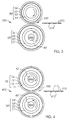
- FIG. 3
- depicts an end view of a simplex toner fusing station which includes an
internally-heated compliant fuser roller which includes a seamless stiffening
layer, engaged in a fusing nip with a compliant pressure roller which
includes a seamless stiffening layer.
- FIG. 4
- depicts an end view of a duplex toner fusing station which includes an
internally-heated compliant first fuser roller which includes a seamless
stiffening layer, engaged in a fusing nip with an internally-heated compliant
second fuser roller which includes a seamless stiffening layer.
- FIG. 5
- is a sketch of the outside of a fuser roller having marked on its outer
surface a descriptive indicia located in a small area located close to an end
of the roller in accordance with the invention.
- FIG. 6
- is a diagrammatic representation of an indicia in the form of a bar code and
its detection by an indicia indicator.
- FIG. 7
- shows a diagrammatic representation of a roller according to this invention,
provided with a stiffening layer having a longitudinally variable Young's
modulus.
- FIG. 8
- shows a diagrammatic representation of a roller according to this invention,
provided with a stiffening layer having a thickness that varies along the
length of the roller.
- FIG. 9
- shows a diagrammatic representation of a roller according to this invention,
having a stiffening layer provided with a plethora of holes, with the
combined area occupied by the holes varying along the length of the roller.
- FIG. 10
- shows a diagrammatic representation of a roller according to this invention,
having a stiffening layer which includes a mesh or fabric in which the mesh
density or fabric density is variable along the length of the roller.
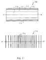
- FIG. 11
- shows a diagrammatic representation of a roller according to this invention,
having a stiffening layer which includes a cordage in which the cordage
density is variable along the length of the roller.
- FIG. 12
- shows a diagrammatic representation of a roller according to this invention,
provided with a stiffening layer having a depth within the roller that varies in
a direction parallel to the roller axis.
- FIG. 13
- shows a diagrammatic representation of a roller of an inventive fusing
station, the roller including a stiffening layer which is shorter than the length
of a receiver, as measured parallel to the fuser roller axis.
- FIG. 14
- shows a diagrammatic representation of a roller of an inventive fusing
station, the roller having an outer diameter that varies along the length of
the roller, the roller including an outer compliant layer which is thicker
towards the ends of the roller than it is at substantially the midpoint along
the length of the roller.
Detailed Description of the Preferred Embodiments
-
Because apparatus of the type described herein are well known, the present description
will be directed in particular to subject matter forming part of, or cooperating more directly
with, the present invention.
-
The invention relates to electrostatographic reproduction utilizing a fusing station to
thermally fuse an unfused toner image to a receiver, e.g., paper. The fusing station
preferably includes two rollers which are engaged to form a fusing nip in which an
internally heated fuser roller comes into direct contact with the unfused toner image as the
receiver is frictionally moved through the nip. The internally heated roller is heated by a
heat source located beneath an outer surface of the roller which is the rolling surface. The
receiver can consist of a cut sheet or it can be a continuous web. The unfused toner
image can include a single-color toner or it can include a composite image of two or more
single-color toners, e.g., a full color composite image made for example from black, cyan,
magenta, and yellow toners. The unfused toner image is previously transferred, e.g.,
electrostatically, to the receiver from a toner image bearing member such as a primary
image-forming member or an intermediate transfer member. The electrostatographic
reproduction can utilize a photoconductive electrophotographic primary image-forming
member or a non-photoconductive electrographic primary image-forming member.
Particulate dry or liquid toners can be used.
-
A simplex fusing station of the invention can include several embodiments. In the most
preferred embodiment, applicants claim a novel compliant internally heated fuser roller
which includes a stiffening layer, engaged in a fusing nip with a hard pressure roller. In
this embodiment, a distorted shape of the compliant roller in the nip helps to release the
receiver from the fuser roller and tends to guide it more towards the hard pressure roller
as the receiver passes out of the nip. In two other preferred embodiments, a hard
internally heated fuser roller is engaged in a fusing nip with a compliant pressure roller
which includes a stiffening layer, or a compliant internally heated fuser roller which
includes a stiffening layer is engaged in a fusing nip with a compliant pressure roller which
also includes a stiffening layer. A simplex fusing station of the invention can be used to
fuse an unfused toner image to one side of a receiver which already has a previously
fused toner image on the reverse side.
-
A preferred embodiment of a duplex fusing station of the invention includes a compliant
internally heated first fuser roller which includes a stiffening layer, engaged in a fusing nip
with a compliant internally heated second fuser roller which includes a stiffening layer. The
duplex fusing station simultaneously fuses two unfused toner images, one on the front and
one on the back of the receiver.
-
In other embodiments, the stiffening layer of a roller of a fusing station is provided with an
axial variation of stiffness, i.e., having a variation parallel to the roller axis, the stiffness
being measured parallel to a tangential direction of rotation of the roller. It is preferred that
the stiffness of the stiffening layer is greatest half way along the length of the roller, and
least near each end of the roller.
-
In additional embodiments, a roller of a fusing station is provided with a stiffening layer
which is located at different depths along the length of the roller. It is preferred for a fusing
roller that the stiffening layer is located deepest near each end of the roller, and
shallowest substantially half way along the length of the roller.
-
In yet other embodiments, a roller of a fusing station including a stiffening layer is provided
with a core member which has a variable bending stiffness that varies along a direction
parallel to the roller axis. It is preferred that said variable bending stiffness of a fuser roller
has a minimum value located substantially at the midpoint along the length of the roller,
and has maximum values near the ends of the roller.
-
In still other embodiments, a roller of a fusing station including a stiffening layer is
provided with an outside diameter which varies along a direction parallel to the roller axis.
Preferably, a maximum of said outside diameter of a fuser roller is located near each end
of the roller and a minimum is located substantially half way along the length of the roller.
-
In yet still other embodiments, a roller of a fusing station including a stiffening layer is
provided with a core member having an outer diameter that varies axially systematically,
such that the outer diameter of the core is a minimum substantially half way along the
length of the core member and becomes gradually larger towards each end of the core
member.
-
In further embodiments, an internally heated fuser roller includes a stiffening layer which is
shorter than the length of a receiver measured parallel to the fuser roller axis when the
fuser roller is being utilized for fusing a toner image to a receiver.
-
In all embodiments, inventive rollers are preferably cylindrically symmetrical, i.e., a cross-section
of the roller taken at right angles to the roller axis anywhere along the length of the
roller has radial symmetry around the roller axis.
-
Although not explicitly disclosed in the preferred embodiments, it will be understood that
an optional supplementary source of heat for fusing, either external or internal, can be
provided to any roller included in a fusing station of the invention.
-
Referring now to the accompanying drawings, FIG. 1 shows the most preferred
embodiment of an inventive simplex fuser station, designated by the numeral 100. A
rotating fuser roller 20 moving in the direction indicated by an arrow includes a cylindrical
core 21, a relatively thick compliant layer 22 formed on the core, a seamless stiffening
layer 23 in intimate contact with and surrounding the compliant layer 22, and a compliant
release layer or outer compliant layer 24 coated on the stiffening layer. (Henceforth the
terms "release layer" and "outer compliant layer" are used interchangeably and mean the
same thing). A counter-rotating hard pressure roller 30 moving in the direction of an
indicated arrow forms a fusing nip 120 with compliant fuser roller 20. A receiver sheet 110
carrying an unfused toner image 111 facing the fuser roller 20 is shown approaching nip
120. The receiver sheet is fed into the nip by employing well known mechanical means
(not shown) such as a set of rollers or other means such as a moving web. The fusing
station preferably has one driving roller, either the fuser roller or the pressure roller, the
other roller being driven and rotated frictionally by contact.
-
The pressure roller 30 includes a core member 31 and an optional surface layer 32 coated
on the core. The core can be made of any suitable rigid material, e.g., aluminum,
preferably including a cylindrical tube. Optional surface layer 32 is preferred to be less
than about 1.25 mm thick and preferably includes a thermally stable preferably low-surface-energy
compliant or conformable material, for example a silicone rubber, e.g., a
PDMS, or a fluoroelastomer such as a Viton™ (from DuPont) or a Fluorel™ (from
Minnesota Mining and Manufacturing). Alternatively, layer 32 can include a relatively hard
poly(tetrafluoroethylene) or other suitable polymeric coating. A bare core having no layer
32 can include, for example, anodized aluminum or copper.
-
The heat source can include, for example, an electrically resistive element located inside
a preferably thermally conductive core member 21, the resistive element being ohmically
heated by passing electrical current through it. For example, an axially centered tubular
incandescent heating lamp, such as lamp 40, or an ohmically heated resistive filament or
other suitable interior source of heat within the core member, can be used. Preferably, the
heat source is controlled by a feedback circuit. For example, a thermocouple can be used
to monitor and thereby control the surface temperature of fuser roller 20 by employing a
programmable voltage power supply (not shown) to regulate the temperature of lamp 40.
-
In alternative embodiments of internal heating, the heat source can be located within the
body of the fuser roller outside the core member, in which case the core member need not
be thermally conductive. For example, the stiffening layer can be electrically resistive and
the internal source of heat can include ohmic heating of the stiffening layer by passing
electrical current through it, or the stiffening layer can include an electrically resistive
printed circuit on its surface and the internal source of heat can include ohmic heating of
the printed circuit. The internal source of heat can also include ohmic heating of an array
of one or more electrically resistive wires located within or in close proximity to the
stiffening layer. In these alternative embodiments, feedback control of the surface
temperature of the fuser roller is easier than when the heat source is inside the core (as
shown in FIG. 1) owing to the fact that the source of heat is located much closer to the
rolling surface of the roller, i.e., the heat capacitance of the material between the heat
source and the rolling surface of the roller is considerably less. As a result, the thermal
response time is advantageously much reduced, making possible more rapid adjustments,
as can be needed, of the surface temperature of the roller. In some applications it can be
desirable to provide both a heat source inside the core as well as a heat source in the
vicinity of, or in, the stiffening layer.
-
At least one of any layers located outward of the internal heat source is thermally
conductive, whether the heat source is located within the core member or outside the core
member. A thermally conductive layer as described herein is a layer having a thermal
conductivity greater than or equal to about 0.08 BTU/hr/ft/°F.
-
The fuser roller 20 includes a rigid core member preferably in the form of a cylindrical tube
21 made from any suitable material, e.g., aluminum. The core member can have internal
reinforcing members, e.g., struts, or other internal strengthening structures (not shown).
Coated on the core member 21 is a relatively thick compliant base cushion layer (BCL)
designated 22. To promote adhesion between the core and the BCL, a thin primer layer
(not shown in FIG. 1) can be used, such as for example made from air-dried GE 4044
priming agent (sold by General Electric). In intimate contact with and surrounding the BCL
is a thin stiffening layer 23. Intimate contact is defined as an interface substantially free of
bubbles or voids, and can be adhesive or non-adhesive. Coated on the stiffening layer
(SL) is a relatively thin release layer or outer compliant layer (OCL) designated 24. The
BCL and OCL can be made of different compliant materials.
-
The base cushion layer 22 can include any suitable thermally stable elastomeric material,
such as a fluoroelastomer, e.g., a Viton™ (from DuPont) or a Fluorel™ (from Minnesota
Mining and Manufacturing) further including a suitable particulate filler to provide a useful
thermal conductivity. Alternatively, the BCL can include a rubber, such as an EPDM
rubber made from ethylene propylene diene monomers further including a particulate filler,
preferably of iron oxide. The BCL can also include an addition cured silicone rubber which
includes a chromium (III) oxide filler. However, it is preferred that the BCL includes a
condensation-cured poly(dimethylsiloxane) elastomer further including a filler which can
be aluminum oxide, iron oxide, calcium oxide, magnesium oxide, nickel oxide, tin oxide,
zinc oxide, or mixtures thereof. This filler preferably includes particles having a mean
diameter between 0.1 micrometer and 100 micrometers and 5 to 50 volume percent of the
base cushion layer, and more preferably, a mean diameter between 0.5 micrometer and
40 micrometers and 10 to 35 volume percent of the base cushion layer. In a preferred
embodiment, the filler includes zinc oxide particles. The base cushion layer 22 preferably
has a thickness between 0.25 mm and 7.5 mm, and more preferably, between 2.5 mm
and 5 mm. The BCL preferably has a thermal conductivity in a range between 0.08 to 0.7
BTU/hr/ft/°F, and more preferably, in a range of 0.2 BTU/hr/ft/°F - 0.5 BTU/hr/ft/°F. The
BCL also has a Poisson's ratio preferably between 0.4 and 0.5, and more preferably,
between 0.45 and 0.5. In addition, the base cushion layer preferably has a Young's
modulus in a range of 0.05 MPa - 10 MPa, and more preferably, 0.1 MPa - 1 MPa.
-
The stiffening layer 23 can be included of any suitable material, including metal,
elastomer, plastic, woven material, fabric, cordage, mesh or reinforced material such as,
for example, a reinforced silicone rubber belt. A cordage is defined as a continuous strand
of any suitable material or a portion thereof wound around the roller, where the number of
windings per unit length along the roller can be systematically varied. Alternatively, a
cordage can include individual rings or loops of any suitable material, the loops being
concentric with the roller axis, and the number of loops per unit length measured axially
along the roller can be systematically varied. A material which is impervious to penetration
by fuser oil is preferred, inasmuch it is known that elevated temperature contact with fuser
oil can deleteriously affect a base cushion layer and cause it to have a reduced
operational life. It is preferred that the SL has good thermal conductance, which helps to
reduce variations in temperature near the surface of the roller and thereby improves
fusing uniformity and image quality. The stiffening layer 23 can be adhesively bonded to
the BCL 22. The SL preferably includes a suitably flexible high-modulus metal or plated
metal, including e.g., copper, gold, steel, and more preferably, nickel. Not as preferably,
the SL can include a sol-gel or a ceramer or an elastomer such as for example a
polyurethane, a polyimide, a polyamide or a fluoropolymer, the SL having a yield strength
which is not exceeded during operation of the roller. The stiffening layer preferably has the
form of a seamless endless belt. Less preferably, the stiffening layer can include a sheet
wrapped around the base cushion layer and smoothly joined by a seam to create an
endless belt, and the seam can include an adhesive or a weld. It is preferable that the
stiffening layer has a thickness in a range of 10 micrometers - 500 micrometers, and more
preferable, 75 micrometers - 250 micrometers. The Young's modulus of the SL is
preferably between 0.25 GPa and 500 GPa, and more preferably, 10 GPa - 300 GPa. The
thickness of the stiffening layer is preferably between 10 micrometers and 500
micrometers, and more preferably, 75 micrometers - 250 micrometers.
-
The outer compliant layer or compliant release layer 24 preferably has a highly smooth
outermost surface. The OCL is preferred to be highly resistant to abrasion, and can
include any suitable elastomeric material preferably having a low surface energy, such as
for example a silicone rubber, or a fluoroelastomer. The OCL can include for example a
PDMS, preferably an addition-cured poly(dimethylsiloxane) elastomer and silica and
titania fillers. The OCL has a roughness value, Ra, no greater than about 10 microinches,
as determined by measurements on a 15-inch long roller using a Federal Surfanalyzer
4000 Profilometer provided with a transverse chisel stylus moving at a speed of 2.5
mm/sec. A release layer 24 providing suitable smoothness, of which the composition and
coating method are disclosed by Chen et al. in US Application Serial No. 08/879,896, can
include Silastic™ E RTV silicone rubber available from Dow Corning Corporation. The
compliant release layer has a thickness preferably less than 500 micrometers, and more
preferably in a range between 25 micrometers and 250 micrometers. The OCL
preferably has a thermal conductivity in a range of 0.2 - 0.5 BTU/hr/ft/°F, and a
Young's modulus between 0.05 MPa and 10 MPa, more preferably 0.1 MPa - 1 MPa. The
Poisson's ratio of the OCL is preferably between 0.4 and 0.5, and more preferably,
between 0.45 and 0.5. The compliant release layer further includes a particulate filler
which can be aluminum oxide, iron oxide, calcium oxide, magnesium oxide, nickel oxide,
tin oxide, zinc oxide, copper oxide, titanium oxide, silicon oxide, graphite, and mixtures
thereof, and preferably zinc oxide. The particulate filler preferably includes 5 to 50 volume
percent of said release layer, and more preferably, 10 to 35 volume percent. Preferably,
the filler helps to provide good thermal conductivity in the OCL, which reduces variations
in temperature near the surface of the roller and thereby improves fusing uniformity and
image quality.
-
If the selected stiffening layer 23 is not impervious to fuser oil, an optional thin barrier
layer (not shown in FIG. 1) can be coated on the stiffening layer underneath the OCL 24.
The barrier layer preferably includes a fluoropolymer and 20 to 40 volume percent of a
particulate filler. The fluoropolymer is preferably a random copolymer formed from
mixtures of monomer units selected from vinylidene fluoride, tetrafluoroethylene, and
hexafluoropropylene. The filler can be aluminum oxide, iron oxide, calcium oxide,
magnesium oxide, nickel oxide, tin oxide, and mixtures thereof. Preferably the optional
barrier layer has a thickness in a range of approximately 10 micrometers to 50
micrometers. The barrier layer can be thicker when coated on a stiffening layer including a
semi-open structure such as a woven material or a fabric.
-
The preferred fuser roller 20 including a stiffening layer in the form of an endless
seamless belt is preferably made in three steps. The first step is to provide the core
member 21 uniformly coated with the base cushion layer 22. In the second step, the
SL 23 in the shape of a seamless metal tube, preferably an electroformed belt preferably
made of nickel available from Stork Screens America, Inc., of Charlotte, North Carolina, is
mounted on a mandrill and coated with the release layer. The inner diameter of the as-purchased
electroformed belt is a little smaller than the outside diameter of the BCL on
the core, typically about 300 micrometers smaller. In the third step, the electroformed belt
coated by the OCL is slid over the BCL on the core to create a completed roller 20. To
accomplish the third step, the core plus base cushion layer can be cooled to a low
temperature in order to contract it, so that the OCL-coated electroformed belt having a
higher temperature can be slid into place. When the assembled roller is returned to room
temperature, the stiffening layer is placed under tension so as to snugly and uniformly
clasp the BCL. Alternatively, the third step can be accomplished by using a well-known
compressed air assist technique to elastically stretch the OCL-coated electroformed tube
slightly so that it can be slid into place. After the coated SL is satisfactorily placed in a
suitable position on the base cushion layer, and the compressed air turned off, the
stretched SL relaxes and grips the stiffening layer snugly. Although the SL in its final
position after the third step is preferably in intimate non-adhesive contact with the BCL, an
adhesive coating can be applied to the BCL surface in order to adhesively bond the SL to
the BCL.
-
A second preferred embodiment of an inventive simplex fusing station is shown as 200 in
FIG. 2. It includes an internally heated hard fuser roller 60, and a compliant pressure roller
50 including a stiffening layer. A receiver sheet 210 carrying an unfused toner image 211
is shown approaching a fusing nip 220 formed by engaged rollers 50 and 60.
-
The fuser roller 60 includes a rigid cylindrical core member 61, preferably made from
aluminum, and a low-surface-energy compliant outer layer 62 coated on the core. Layer
62 is preferred to be than 1.25 mm thick and can include a poly(tetrafluoroethylene) or
another hard preferably low-surface-energy polymer, or more preferably includes a
compliant or conformable preferably low-surface-energy layer including a silicone rubber,
e.g., a PDMS, or a fluoroelastomer such as a Viton™ (from DuPont) or a Fluorel™ (from
Minnesota Mining and Manufacturing).
-
The heat source can include, for example, an electrically resistive element located inside
a preferably thermally conductive core member 21, the resistive element being ohmically
heated by passing electrical current through it. For example, an axially centered tubular
incandescent heating lamp, such as lamp 40, or an ohmically heated resistive filament or
other suitable interior source of heat within the core member, can be used. Preferably, the
heat source is controlled by a feedback circuit. For example, a thermocouple can be used
to monitor and thereby control the surface temperature of fuser roller 20 by employing a
programmable voltage power supply (not shown) to regulate the temperature of lamp 40.
-
The compliant pressure roller 50 includes a rigid cylindrical core member 51, preferably
made from aluminum, a compliant base cushion layer 52 coated on the core member, a
stiffening layer 53 preferably in the form of a seamless endless belt in intimate contact
with and surrounding layer 52, and an optional outer compliant layer 54. The base cushion
layer 52 includes a suitable thermally stable elastomer, e.g., a fluoroelastomer, an EPDM
rubber, a PDMS, or other suitable material preferably having thickness between 0.25 mm
and 25 mm. The BCL preferably has a Young's modulus in a range of 0.05 MPa to 10
MPa and can further include a particulate filler or a foam. Base cushion layer 52 has a
Poisson's ratio preferably between 0.2 and 0.5 and more preferably between 0.45 and 0.5.
The BCL and OCL can be the same or different materials.
-
The stiffening layer 53 includes a thin, flexible, preferably high-modulus material having
characteristics similar to those disclosed above for layer 23 of FIG. 1. Preferably, the
stiffening layer is a seamless belt and is made of nickel.
-
The optional outer compliant layer 54 includes an elastomer, such as for example a
PDMS or a fluoropolymer, having a thickness preferably less than 500 micrometers. Layer
54 preferably has a Young's modulus in a range of 0.05 MPa - 10 MPa, and a Poisson's
ratio preferably between 0.2 and 0.5 and more preferably between 0.45 and 0.5.
-
The preferred pressure roller 50 including a stiffening layer in the form of an endless
seamless belt is preferably made in three steps. The first step is to provide the core
member 51 uniformly coated with the base cushion layer 52. In the second step, the SL
53 in the shape of a seamless metal tube, preferably an electroformed belt preferably
made of nickel available from Stork Screens America, Inc., of Charlotte, North Carolina, is
mounted on a mandrill and coated with the release layer. The inner diameter of the as-purchased
electroformed belt is a little smaller than the outside diameter of the BCL on
the core, typically about 300 micrometers smaller. In the third step, the electroformed belt
coated by the OCL is slid over the BCL on the core to create a completed roller 50. To
accomplish the third step, the core plus base cushion layer can be cooled to a low
temperature in order to contract it, so that the OCL-coated electroformed belt having a
higher temperature can be slid into place. When the assembled roller is returned to room
temperature, the stiffening layer is placed under tension so as to snugly and uniformly
clasp the BCL. Alternatively, the third step can be accomplished by using a well-known
compressed air assist technique to elastically stretch the OCL-coated electroformed tube
slightly so that it can be slid into place. In order to aid sliding, a lubricating aid can be
applied to either the BCL outer surface or the inner surface of the SL belt. Lubricating aids
include materials which can produce a low-surface-energy sliding interface, such as for
example sub-micron particles of silica and the like, zinc stearate, or other suitable
materials. After the coated SL is satisfactorily placed in a suitable position on the base
cushion layer, and the compressed air turned off, the stretched SL relaxes and grips the
stiffening layer snugly. Although the SL in its final position after the third step is preferably
in intimate non-adhesive contact with the BCL, an adhesive coating can be applied to the
BCL surface in order to adhesively bond the SL to the BCL.
-
A third preferred embodiment of an inventive simplex fusing station is shown as 300 in
FIG. 3, in which primed (') entities correspond to similar entities labeled by unprimed
numerals in FIGS. 1 and 2. The material and physical characteristics of the primed entities
are qualitatively and quantitatively the same as disclosed above for the unprimed entities,
whereupon fusing station 300 includes an internally heated compliant fuser roller 20'
including a stiffening layer preferably in the form of a seamless belt, and a compliant
pressure roller 50' also including a stiffening layer preferably in the form of a seamless
belt. A receiver sheet 310 carrying an unfused toner image 311 is shown approaching a
fusing nip 320 formed by engaged rollers 20' and 50'. Fuser roller 20' includes a rigid
cylindrical core 21', a base cushion layer 22' formed on the core, a stiffening layer 23' in
intimate contact with and surrounding the BCL, and a release layer 24' coated on the SL.
Fuser roller 20' having a preferably thermally conductive core 21' can be heated by an
internal source of heat, such as provided for example by lamp 40', or alternatively the
source of heat can include ohmic heating produced by passing electrical current through
an element in the body of the roller outside the core, e.g., by passing electrical current
through a resistive stiffening layer 23', or passing an electrical current through an
electrically resistive printed circuit the surface of the stiffening layer, or through an array of
one or more electrically resistive wires located within or in close proximity to the stiffening
layer. Pressure roller 50' includes a rigid cylindrical core 21', a base cushion layer 22'
formed on the core, a stiffening layer 23' in intimate contact with and surrounding the BCL,
and an outer compliant layer 24' coated on the SL. The BCL and OCL can be made of
different materials.
-
A preferred embodiment of an inventive duplex fusing station is shown as 400 in FIG. 4. A
first rotating fuser roller indicated as 20" includes a rigid cylindrical core 21", a base
cushion layer 22" formed on the core, a stiffening layer 23" preferably in the form of a
seamless belt in intimate contact with and surrounding the BCL, and a release layer 24"
coated on the SL. The doubly-primed entities correspond to similar entities labeled by
unprimed numerals in FIG. 1, and the material and physical characteristics of the doubly-primed
entities are qualitatively and quantitatively the same as those disclosed above for
the unprimed entities. A second counter-rotating fuser roller 70 forms a fusing nip 420 with
the first fuser roller 20". The second fuser roller has the same structure as the first fuser
roller, i.e., includes a rigid cylindrical core 71, a base cushion layer 72 formed on the core,
a stiffening layer 73 preferably in the form of a seamless belt in intimate contact with and
surrounding the BCL, and a release layer 74 coated on the SL. A receiver sheet 411 is
shown approaching fusing nip 420. On each side of the receiver is an unfused toner
image, labeled 411 and 412, respectively. The second fuser roller 70 is similar in other
ways to the first fuser roller, inasmuch as it includes the same choices of materials and
the same ranges of physical and material parameters as disclosed above for the fuser
roller 20 of the first simplex embodiment. However, the two fuser rollers 20" and 70 can
differ in specific dimensions, such as for example roller diameters, layer thicknesses, and
so forth, and can also differ in specific choices of materials and material properties. In
particular, the BCL and OCL in each roller can include the same or different compliant
materials.
-
In the above disclosed preferred embodiments of inventive simplex and duplex fusing
stations, the use of stiffening layers in compliant fuser and compliant pressure rollers
reduces the propensity to overdrive, thereby markedly reducing wear as compared to prior
rollers, especially of fuser rollers in contact with relatively hard and abrasive receivers
such as paper. Image smear during fusing is also reduced and image quality thereby
increased.
-
In order to help delineate the ranges of preferred parameters of the rollers claimed below
by applicants, such as layer thicknesses, moduli, Poisson's ratios, and so forth, a
computer was used to solve a finite element model of a simulated fusing nip in which a
compliant roller including a stiffening layer is engaged with a hard roller. The calculations
show, for example, that a minimum useful value of Young's modulus of a stiffening layer is
very probably lower than 80,000 MPa. Therefore, in addition to a preferred metallic
stiffening layer, a high-modulus non-metallic material can be useful.
Example 1
Rate of Wear of a Compliant Fuser Roller
-
In order to anticipate the effect of a stiffening layer on reducing wear rate, a preliminary
experiment was carried out to study whether the wear rate of a fuser roller having a
compliant base cushion layer but no stiffening layer is dependent upon the thickness of
the compliant base cushion layer. Two companion life tests were carried out in a full-process
experimental electrophotographic machine, using two different compliant fuser
rollers operated in a fusing station employing a new pressure roller of the same
manufacture and same composition for each test. In the first test, the fuser roller was
made from a 6.0" diameter aluminum core coated with a 0.20" layer of a red rubber (EC
4952 from Emerson Cummings), with the red rubber layer further coated by a 0.001" layer
of a silicone rubber including an interpenetrating polymer network (IPN) as described by J.
Chen et al., U.S. Patent 5,582,917. In the second test, the fuser roller was the same
except the red rubber layer was half as thick, i.e., 0.10". For each test, the pressure roller
was made from a 3.5" diameter aluminum core coated with a 0.20" base cushion layer of
IPN covered by a 0.001" layer of a fluoroelastomer (S5100 from Emerson Cummings). In
both tests, the fuser roller surface temperature was controlled at 320°F, the engagement
force between fuser and pressure rollers was the same in a constant force nip, and the
same type of paper and toner image were used. After 100,000 prints had been made in
each test, wear tracks caused by the paper receivers having depth 0.005" - 0.008" were
observed on the fuser roller having the thicker 0.20" red rubber blanket, but no
measurable wear was observed on the fuser roller having the thinner 0.10" red rubber. It
was concluded that the larger amounts of overdrive and flexure associated with the thicker
red rubber layer were responsible for the much higher wear rate, as compared to the
thinner layer which allowed the hard substrate core to have more influence. This Example
therefore supports implementation of a stiffening layer in rollers requiring thick compliant
layers which, as is well known, are typically needed to provide wide nip footprints
desirable for superior fusing.
-
In certain embodiments described below, it is advantageous to provide a stiffening layer
having a stiffness that varies along the length of a roller, in particular for an inventive
fusing roller. It can also be advantageous to provide a variably stiff stiffening layer for a
compliant pressure roller used in a fusing station of the invention. A variably stiff stiffening
layer of a fuser roller can improve paper transport through a fusing station, particularly
when paper receiver sheets are not perfectly rectangular as a result of humidity-induced
swelling. A typical 8.5" x 11" paper sheet has long paper fibers oriented substantially
parallel to the 11" direction, and moisture penetrates preferentially into the 8.5" edges
typically causing the nominally 8.5" edges to expand by about 1% to 2% compared to the
nominal 8.5" width. It is usual practice to feed such paper sheets into a fuser nip with the
8.5" edges oriented parallel to the paper feeding direction, i.e., perpendicular to the roller
axes. As a result, it typically takes a longer time for the swollen 8.5" edges to pass through
the fusing nip than it does for the middle of the sheet. This can result in severe paper
wrinkling and large scale image defects. To correct this problem, it is preferred that all
portions of the paper spend substantially the same time passing through the nip. A means
to accomplish this is to provide a greater amount of overdrive near the swollen 8.5" edges
of the paper than at the center. As is also well known, a pressure nip formed between two
rollers, at least one of which has an elastomeric coating, does not usually have a uniform
pressure distribution measured in the axial direction along the length of the rollers. Rather,
owing to the fact that the compressive forces are applied at the ends of the rollers, e.g., to
the roller axle, the rollers tend to bow outwards slightly, thereby producing a higher
pressure near the ends of the rollers than half way along their length. This also tends to
produce greater overdrive towards the ends of the rollers. However, the amount of extra
overdrive from roller bending is not normally sufficient to compensate for humidity-induced
paper swelling, and embodiments including a variably stiff stiffening layer can be used.
-
In embodiments described below, a variably stiff stiffening layer is provided to produce a
predetermined variation of overdrive along the length of a roller, e.g., to compensate for
humidity-induced paper swelling. The variably stiff stiffening layer can be included in a
fuser roller, e.g., rollers 20, 20', 20" or 70, or, in a pressure roller, e.g., rollers 50 or 50'.
When a stiffening layer includes a cordage, a fabric, or a woven material, the spaces or
interstices between cords or fibers can be filled by any suitable material, including a
material of an adjacent layer of an inventive roller.
-
In an embodiment utilizing a variably stiff stiffening layer, the stiffening layer of a roller of a
fusing station according to the invention is provided with a Young's modulus that varies
systematically parallel to the roller axis, the modulus being measured parallel to a
tangential direction of rotation of the roller. It is preferred that the modulus of the stiffening
layer of an inventive roller be greatest substantially midway along the length of the roller,
and least near each end of the roller. As a result, when the roller is engaged in the fusing
nip, there will be an increased amount of overdrive provided by the reduced stiffness of
the stiffening layer near the edges of a paper sheet, as compared to the center of the
paper, thereby providing a mechanism to ensure that all portions of the paper sheet spend
substantially the same time passing through the nip. In this embodiment, the stiffening
layer can include a continuous, thin, seamless metal tube in which the Young's modulus
can be controlled, for example, by providing the metal as an alloy having a variable
composition parallel to the roller axis. Alternatively, the stiffening layer can include a
cordage in which the Young's modulus is changed systematically as a function of position
along the roller, or the stiffening layer can include any other suitable material for which the
Young's modulus can be systematically controlled and varied. FIG. 7 shows a longitudinal
cross section of a diagrammatic representation of an exemplary inventive cylindrically
symmetric roller, indicated as 500, provided with a stiffening layer 512 having a variable
Young's modulus. Roller 500 includes a rigid core member 510, a compliant base cushion
layer 511 formed on the core member, a stiffening layer 512 surrounding and in intimate
contact with the base cushion layer 511 with stiffening layer 512 having a Young's
modulus variable in a direction parallel to an axis of rotation indicated by D...D', and an
outer compliant layer 513 on the stiffening layer. Stiffening layer 512 is shown with
hatchings in which the density of hatching lines represents the magnitude of Young's
modulus, with Young's modulus of stiffening layer 512 increasing from a minimum value at
each end of the roller 500 towards a maximum value located at substantially the midpoint
along the length of the roller. For clarity of understanding, the thickness of stiffening layer
512 has been greatly exaggerated. The longitudinal variation of Young's modulus of
stiffening layer 512 can be smooth from an end of the roller 500 to substantially the
midpoint,, as indicated in FIG. 7, or it can have more or less abrupt changes. For
example, individual longitudinal lengths or sections having discretely different Young's
moduli can be used to make layer 512, where the individual lengths can be different
materials. The individual longitudinal lengths need not be joined to form a continuous tube
but can be separated by gaps, the gaps being preferably small enough so as to cause no
noticeable effects at the exterior surface of compliant layer 513 that could result in a
decreased fusing performance or quality. Moreover, the maximum value of Young's
modulus can, if desired, extend for a suitable distance on either side of substantially the
midpoint along the length of the roller 500.
-
In a further embodiment utilizing a variably stiff stiffening layer, the stiffening layer of a
roller of a fusing station according to the invention is provided with a thickness that varies
systematically parallel to the roller axis. It is preferred that the thickness of the stiffening
layer of an inventive roller be greatest substantially midway along the length of the roller,
and least near each end of the roller. As a result, when the roller is engaged in the fusing
nip, there will be an increased amount of overdrive provided by the reduced thickness of
the stiffening layer near the edges of a paper sheet, as compared to the center of the
paper, thereby providing a mechanism to ensure that all portions of a paper sheet spend
substantially the same time passing through the nip. In this embodiment, the stiffening
layer preferably includes a continuous, seamless, thin metal tube in which the thickness
can be systematically varied parallel to the roller axis. Alternatively, the stiffening layer can
include a cordage in which the thickness of the cords is changed systematically as a
function of position along the roller, or the stiffening layer can include any other suitable
material for which the thickness can be systematically controlled and varied. FIG. 8 shows
a longitudinal cross section of a diagrammatic representation of an exemplary inventive
cylindrically symmetric roller, indicated as 550, provided with a stiffening layer 562 having
a thickness that varies systematically parallel to the roller axis. Roller 550 includes a rigid
core member 560, a compliant base cushion layer 561 formed on the core member, a
stiffening layer 562 surrounding and in intimate contact with the base cushion layer 561
with the stiffening layer 562 having a thickness variable in a direction parallel to an axis of
rotation indicated by E...E', and an outer compliant layer 563 on the stiffening layer.
Stiffening layer 562 is shown with a thickness increasing from a minimum value at each
end of the roller 550 towards a maximum value located at substantially the midpoint along
the length of the roller. For clarity of understanding, the thickness of stiffening layer 562
has been greatly exaggerated along the entire length of the roller 550. The longitudinal
variation of thickness of stiffening layer 562 can be smooth from an end of the roller 550 to
substantially the midpoint, as indicated in FIG. 8, or it can have more or less abrupt
changes. For example, individual longitudinal lengths or sections having discretely
different thicknesses can be used to make layer 562. The individual longitudinal lengths
need not be joined to form a continuous tube but can be separated by gaps, the gaps
being preferably small enough so as to enough so as to cause no noticeable effects at the
exterior surface of compliant layer 563 that could result in a decreased fusing
performance or quality. Moreover, the maximum value of thickness of stiffening layer 562
can, if desired, extend for a suitable distance on either side of substantially the midpoint
along the length of the roller 550. The stiffening layer 562 having a variable thickness can
also include a mesh or a cordage (not illustrated) such that the diameters of the fibers,
threads or wires of which the mesh or cordage is made are systematically varied so as to
have a minimum diameter at or near each end of the roller 550 and a maximum diameter
at substantially the midpoint along the length of roller 550.
-
In another embodiment utilizing a variably stiff stiffening layer, the stiffening layer of a
roller of a fusing station according to the invention is provided with a plethora of holes,
preferably small holes, with the combined area occupied by the holes varying
systematically along the length of the roller parallel to the roller axis. This can be
accomplished by changing number of holes per unit area along the length of the roller, or
by changing the area per hole along the length of the roller, or by a combination of
variation of hole size and area per hole along the length of the roller. The holes can,
therefore, have different sizes at different locations in the stiffening layer. It is preferred
that the fractional area occupied by holes per unit length of an inventive roller be smallest
substantially midway along the length of the roller, and greatest near each end of the
roller. As a result, when the roller is engaged in the fusing nip, there will be an increased
amount of overdrive provided by larger amount of strain in the stiffening layer near the
edges of a paper sheet, as compared to the center of the paper, thereby providing a
mechanism to ensure that all portions of a paper sheet spend substantially the same time
passing through the nip. In this embodiment, the stiffening layer preferably includes a
continuous, seamless, thin metal tube in which the holes can be provided, e.g., formed by
punching, drilling, etching, or by using a laser. Alternatively, the stiffening layer can
include any other suitable material in which the holes can be systematically be provided,
such as a plastic or reinforced material. FIG. 9 shows a longitudinal cross section of a
diagrammatic representation of an exemplary inventive cylindrically symmetric roller,
indicated as 600, having a stiffening layer 612 provided with a plethora of holes,
preferably small holes, with the combined area occupied by the holes varying
systematically per unit length along the length of the roller parallel to the roller axis. Roller
600 includes a rigid core member 610, a compliant base cushion layer 611 formed on the
core member, a stiffening layer 612 surrounding and in intimate contact with the base
cushion layer 611 with stiffening layer 612 having an area occupied by holes variable in a
direction parallel to the roller axis of rotation indicated by F...F', and an outer compliant
layer 613 on the stiffening layer. For clarity of understanding, an embodiment of a
stiffening layer 612' is depicted in the tubular representation shown in FIG. 9, in which a
number per unit area of similar-sized holes 614 is shown varying, in a direction parallel to
axis F''...F''', from a maximum value at or near each end of the stiffening layer 612'
towards a minimum value located at substantially the midpoint along the length of the
stiffening layer. For clarity, only a few approximately round holes 614 having exaggerated
sizes are indicated in FIG. 9, the holes preferably having diameters which are smaller than
the thickness of the stiffening layer. The holes can have any suitable shapes, including
random shapes. Different sized holes can be used at different locations, and holes of
different sizes can be used together in any local area of the stiffening layer 612. For an
inventive fuser roller, it is preferred that the holes be small enough to produce no
measurable effect on fusing uniformity. It is to be understood that, in other suitable
embodiments of stiffening layer 612 (not illustrated), a variation in the total fractional area
occupied by holes along the length of the stiffening layer can be accomplished by varying
the area per individual hole, or by combining a variation of the area per individual hole
with a variation in the number of holes per unit area of the stiffening layer. The longitudinal
variation along the length of the stiffening layer of the area occupied by holes can be
smooth, as indicated for layer 612', or it can have more or less abrupt changes. For
example, individual longitudinal lengths or sections having discretely different fractional
hole areas can be used to make layer 612. The individual longitudinal lengths need not be
joined to form a continuous tube but can be separated by gaps, the gaps being preferably
small enough so as to enough so as to cause no noticeable effects at the exterior surface
of compliant layer 613 that could result in a decreased fusing performance or quality.
Moreover, the minimum value of the area occupied by holes per unit length of the
stiffening layer 612 can, if desired, extend for a suitable distance on either side of
substantially the midpoint along the length of the roller 600. Additionally, the minimum
value of the number of holes per unit area provided or formed in the stiffening layer can be
zero, such that holes can be provided or formed only near each end of the stiffening layer.
When outer compliant layer 613 is formed on the stiffening layer, the material of layer 613
can be made to penetrate and fill the holes. Alternatively, the holes in the stiffening layer
can be filled by any suitable other material, preferably a compliant material, and this is
preferably done before the outer compliant layer 613 is formed on the stiffening layer 612.
-
In a further embodiment utilizing a variably stiff stiffening layer, the stiffening layer of a
roller of a fusing station according to the invention includes a mesh or fabric in which the
mesh density or fabric density is systematically variable along the length of the roller
parallel to the roller axis. The density is proportional to the number of threads or wires per
unit area, i.e., a high density in a given area of the mesh or fabric means a comparatively
large number of threads or wires passing in any given direction, including sets of threads
or wires that cross each other. It is preferred that the mesh or fabric density be lowest
near the ends of an inventive roller, and highest substantially midway along the length of
the roller. As a result, when the roller is engaged in the fusing nip, there will be an
increased amount of overdrive provided by larger amount of strain in the stiffening layer
near the edges of a paper sheet, as compared to the center of the paper, thereby
providing a mechanism to ensure that all portions of the paper sheet spend substantially
the same time passing through the nip. In this embodiment, the fabric or mesh can include
natural or synthetic fibers, threads, metal wires or strips, or any other suitable preferably
flexible material which can be woven into a fabric or mesh having a variable density.
-
FIG. 10 shows a longitudinal cross section of a diagrammatic representation of an
exemplary inventive cylindrically symmetric roller, indicated as 650, having a stiffening
layer 662 which includes a mesh or fabric in which the mesh density or fabric density is
systematically variable along the length of the roller parallel to the roller axis. Roller 650
includes a rigid core member 660, a compliant base cushion layer 661 formed on the core
member, a stiffening layer 662 surrounding and in intimate contact with the base cushion
layer 661 with stiffening layer 662 including a mesh having a density variable in a direction
parallel to the roller axis of rotation indicated by G...G', and an outer compliant layer 663
on the stiffening layer. Stiffening layer 662 is separately indicated diagrammatically in side
view for clarity of understanding. In an embodiment of a stiffening layer 662' depicted in a
side view representation in FIG. 10, a woven fabric 664 is shown having a simple diagonal
mesh, the mesh density varying, in a direction parallel to axis G"...G"', from a minimum
value at or near each end of the stiffening layer 662' towards a maximum value located at
substantially the midpoint along the length of the stiffening layer (crossings of fibers are
not shown in detail). For clarity, a greatly enlarged mesh 664 is indicated in FIG. 10. For
an inventive fuser roller, it is preferred that diameters of the fibers, threads or wires of
which the mesh is made be small enough to produce no measurable effect on fusing
uniformity. Similarly, it is preferred for an inventive fuser roller that the interstices between
the fibers, threads or wires of which the mesh is made be small enough to produce no
measurable effect on fusing uniformity. It is to be understood that, in other suitable
embodiments of the stiffening layer 662 (not illustrated) the mesh can include any suitable
weave, and it can have a simple form of a warp and a woof, or it can include a more
complex weave, with the threads or wires passing in any suitable directions, including
parallel and perpendicular to the axis G...G'. The mesh can be made of one or more
different kinds of fibers, or fibers of one or more different diameters. For example, the
simple mesh of the fabric 664 can be considered to be made of a warp and a woof, with
the warp and woof being optionally made of different materials, or having fibers or threads
of different diameters. The longitudinal variation of the mesh density along the length of
the stiffening layer can be smooth, as depicted for layer 662', or it can have more or less
abrupt changes. For example, individual longitudinal lengths or sections having discretely
different mesh densities can be used to make layer 662. The individual longitudinal
lengths need not be joined to form a continuous tube but can be separated by gaps, the
gaps being preferably small enough so as to cause no noticeable effects at the exterior
surface of compliant layer 663 that could result in a decreased fusing performance or
quality. Moreover, the maximum value of the mesh density of the stiffening layer 662 can,
if desired, extend for a suitable distance on either side of substantially the midpoint along
the length of the roller 650. When outer compliant layer 663 is formed on the stiffening
layer, the material of layer 663 can be made to penetrate and fill the interstices of the
mesh. Alternatively, the interstices of the mesh included in the stiffening layer can be filled
by any suitable other material, preferably a compliant material, and this is preferably done
before the outer compliant layer 663 is formed on the stiffening layer 662.
-
In yet another embodiment utilizing a variably stiff stiffening layer, the stiffening layer of a
roller of a fusing station according to the invention includes a cordage, and the variation of
stiffness is produced by a systematic variation, as measured in the plane of the stiffening
layer, of the density of the cordage, i.e., of the number of cords per unit length cutting a
direction parallel to the axis of rotation of the roller. It is preferred that the cordage density
be lowest near the ends of an inventive roller, and highest substantially midway along the
length of the roller. As a result, when the roller is engaged in the fusing nip, there will be
an increased amount of overdrive provided by larger amount of strain in the stiffening
layer near the edges of a paper sheet, as compared to the center of the paper, thereby
providing a mechanism to ensure that all portions of the paper sheet spend substantially
the same time passing through the nip. In this embodiment, the cordage can include
natural or synthetic fibers, metal wires or strips, or any other suitable material, e.g., in the
form of a wound filament which can for example be wound as a continuous strand around
a compliant layer, or provided in ring form around the compliant layer as a set of rings
having their centers substantially concentric with the axis of rotation of the roller. FIG. 11
shows a longitudinal cross section of a diagrammatic representation of an exemplary
inventive cylindrically symmetric roller, indicated as 700, having a stiffening layer 712
which includes a cordage in which the cordage density is systematically variable along the
length of the roller parallel to the roller axis. Roller 700 includes a rigid core member 710,
a compliant base cushion layer 711 formed on the core member, a stiffening layer 712
surrounding and in intimate contact with the base cushion layer 711, the stiffening layer
712 including a cordage density variable in a direction parallel to the roller axis of rotation
indicated by H...H', and an outer compliant layer 713 on the stiffening layer. For clarity of
understanding, an embodiment of a stiffening layer 712' including a cordage is depicted in
a side view representation in FIG. 11, with individual rings of cordage depicted edge on
labeled 714, the rings of cordage being centered on an axis H"...H"' and having a density
varying, in a direction parallel to axis H"...H"', from a minimum value at or near each end
of the stiffening layer 712' to a maximum value located at substantially the midpoint along
the length of the stiffening layer. For clarity, a greatly reduced cordage density 714 is
indicated in FIG. 11. For an inventive fuser roller, it is preferred that diameters of the
fibers, threads or wires of which the cordage is made be small enough to produce no
measurable effect on fusing uniformity. Similarly, it is preferred for an inventive fuser roller
that the cordage density is made high enough, and the interstices between the fibers,
threads or wires of which the cordage is made be small enough, to produce no
measurable effect on fusing uniformity. It is to be understood that, in other suitable
embodiments of the stiffening layer 712 (not illustrated) the cordage can include any
suitable winding around the base cushion layer 711, in any suitable directions, and there
can also be crossings of the windings, including more than one layer. The cordage can be
made of one or more different kinds of fibers, threads or wires. Alternatively, the cordage
can be made of interspersed fibers, threads or wires having one or more different
diameters. The longitudinal variation of the cordage density along the length of the
stiffening layer can be smooth, as shown for example by the cordage 712', or it can have
more or less abrupt changes. For example, individual longitudinal lengths or sections
having discretely different cordage densities, with the cordage in each of the lengths in the
form of continuous windings, can be used to make layer 712. The individual longitudinal
lengths need not be joined but can be separated by gaps, the gaps being preferably small
enough so as to cause no noticeable effects at the exterior surface of compliant layer 713
that could result in a decreased fusing performance or quality. Moreover, the maximum
value of the cordage density of the stiffening layer 712 can, if desired, extend for a
suitable distance on either side of substantially the midpoint along the length of the roller
700. When outer compliant layer 713 is formed on the stiffening layer, the material of layer
713 can be made to penetrate and fill the interstices of the cordage. Alternatively, the
interstices of the cordage included in the stiffening layer can be filled by any suitable other
material, preferably a compliant material, and this is preferably done before the outer
compliant layer 713 is formed on the stiffening layer 712.
-
In an additional embodiment for providing a predetermined variation of overdrive along the
length of a roller of an inventive fusing station, the roller can be provided with a stiffening
layer which is located at different depths along the length of the roller. It is preferred that
the stiffening layer is located deepest near each end of the roller, and shallowest
substantially midway along the length of the roller. As a result, when the roller is engaged
in the fusing nip, there will be an increased amount of overdrive provided by larger amount
of strain in the stiffening layer near the edges of a paper sheet, as compared to the center
of the paper, thereby providing a mechanism to ensure that all portions of a paper sheet
spend substantially the same time passing through the nip. FIG. 12 shows a longitudinal
cross section of a diagrammatic representation of an exemplary inventive cylindrically
symmetric roller, indicated as 750, provided with a stiffening layer 762 having a depth
within roller 750 that varies systematically in a direction parallel to the roller axis. Roller
750 includes a rigid core member 760, a compliant base cushion layer 761 formed on the
core member, a stiffening layer 762 surrounding and in intimate contact with the base
cushion layer 761 with the stiffening layer 762 having a depth which is variable in a
direction parallel to an axis of rotation indicated by J...J', and an outer compliant layer 763
on the stiffening layer. Stiffening layer 762 is shown at a depth below the compliant layer
increasing from a minimum value at or near each end of the roller 750 towards a
maximum value located at substantially the midpoint along the length of the roller.
Preferably, a sum of the thicknesses of layers 761 and 763 is substantially constant along
the entire length of the roller. For clarity of understanding in FIG. 12, the variation of depth
of stiffening layer 762 has been greatly exaggerated along the entire length of the roller
750. The longitudinal variation of depth of stiffening layer 762 can be smooth from an end
of the roller 750 to substantially the midpoint, as depicted in FIG. 12, or it can have more
or less abrupt changes. For example, individual longitudinal lengths or sections having
discretely different depths below the outer compliant layer 763 can be used to make layer
762. The individual longitudinal lengths need not be joined to form a continuous tube but
can be in the form of individual tubes, made, e.g., of metal, having different diameters, the
tubes being separated by gaps, the gaps being preferably small enough so as to cause no
noticeable effects at the exterior surface of compliant layer 763 that could result in a
decreased fusing performance or quality. Moreover, the maximum value of the depth of
stiffening layer 762 can, if desired, extend for a suitable distance on either side of
substantially the midpoint along the length of the roller 750. The stiffening layer 762
having a variable depth can also include a mesh or a cordage (not illustrated).
-
In a further additional embodiment for providing a predetermined variation of overdrive
along the length of a roller of an inventive fusing station, the roller includes a stiffening
layer which is shorter than the length of a receiver, as measured parallel to the fuser roller
axis. Each edge of a paper sheet passing through the fusing station is preferably located
less than about 2 inches beyond a corresponding end of the stiffening layer, and more
preferably, less than about 1.5 inches beyond a corresponding end of the stiffening layer.
By providing the stiffening layer to be shorter than the length of the fuser roller that
contacts the paper, the overdrive is increased in the areas near the edges of a paper
sheet for which there is no stiffening layer, as compared to rest of the paper, thereby
providing a mechanism to reduce wrinkling of a paper sheet passing through the nip. FIG.
13 shows a longitudinal cross section of a diagrammatic representation of an exemplary
inventive cylindrically symmetric roller, indicated as 800, rotatable about an axis K...K' and
including a rigid core member 810, a compliant base cushion layer 811 formed on the
core member, a stiffening layer 812 surrounding and in intimate contact with the base
cushion layer 811, and an outer compliant layer 813 on the stiffening layer. As indicated in
FIG. 13, the stiffening layer 812 is shorter than the roller 800, so that portions having
indicated respective lengths s and s' located at each end of the outer surface of the base
cushion layer 811 are not covered by the stiffening layer 812. Preferably, the portions of
the base cushion layer 811 not covered by the stiffening layer are of approximately equal
length, and these portions are covered by the outer compliant layer 813. It is preferred
that an outer diameter of roller 800 be uniformly the same along the length of the roller.
This can be accomplished by making the portions of the outer compliant layer 813
correspondingly thicker where there is no underlying stiffening layer 812 on top of base
cushion layer 811, the base cushion layer preferably having a diameter which is uniformly
the same along the length of the roller 800. Alternatively, the outer diameter of roller 800
can be made uniformly the same along the length of the roller by having the base cushion
layer correspondingly thicker where there is no stiffening layer (not illustrated).
-
In a still further additional embodiment for providing a predetermined variation of overdrive
along the length of a compliant roller of an inventive fusing station, the compliant roller
including a stiffening layer can be provided with an outside diameter which varies along a
direction parallel to the roller axis. It is preferred, for an inventive roller, that a maximum of
the outside diameter is located near each end of the roller and a minimum is located
substantially midway along the length of the roller, increasing the overdrive near the
edges of a paper sheet, as compared to the center of the paper, and thereby providing a
mechanism to ensure that all portions of a paper sheet spend substantially the same time
passing through the nip. FIG. 14 shows a longitudinal cross section of a diagrammatic
representation of an exemplary inventive cylindrically symmetric roller, indicated as 850,
having a profiled outer diameter and being rotatable about an axis L...L', roller 850
including a rigid cylindrical core member 860, a compliant base cushion layer 861 formed
on the core member 860, a stiffening layer 862 surrounding and in intimate contact with
the base cushion layer 861, and a longitudinally profiled outer compliant layer 863 on the
stiffening layer. Preferably, each of both the base cushion layer 861 and the stiffening
layer 862 have a substantially uniform thickness along the length of the roller. The outer
compliant layer 863 is thicker towards the ends of roller 850 than it is at substantially the
midpoint along the length of the roller. It can be desirable in certain applications to vary
the outer diameter of roller 850 by including a longitudinally profiled core member 860 (not
illustrated) or a longitudinally profiled base cushion layer 861 (not illustrated) in order to
provide a desired variation of outer diameter along the length of roller 850.
-
FIG. 5 diagrammatically shows an end portion of an inventive roller, indicated as 90, on
which an outer surface has marked on it a set of descriptive markings or indicia which are
provided to indicate a parameter (parameters) relative to the roller. The roller 90 can be
representative of a fuser roller including a stiffening layer, or alternatively roller 90 can be
representative of a roller utilized in a fusing station of the invention, including a pressure
roller including a stiffening layer, a hard fuser roller, or a hard pressure roller. That is, it is
preferred to provide an indicia on the outer surfaces of rollers 20, 20', 20", 30, 50, 50', 60
and 70 according to the manner described for an inventive roller 90. The indicia are
located in a small area 92" located on a portion of the cylindrical surface close to an end
of the roller. Alternatively, the indicia are contained in a small area 92' located on an end
portion of the roller, with area 92' preferably near the edge or rim (the individual layers
including roller 90 are not shown). FIG. 6 shows a diagrammatic representation of an area
92, an enlarged view of either of the areas 92' or 92", and illustrates that the descriptive
indicia can be in the form of a bar code, as indicated by the numeral 93, which can be
read, for example, by a scanner. The scanner can be mounted in an electrophotographic
machine so as to monitor roller 90, e.g., during operation of the machine or during a time
when the machine is idle, or the scanner can be externally provided during installation of,
or during maintenance of, an inventive roller 90. Generally, the indicia can be read,
sensed or detected by an indicia detector 95. As indicated in FIG. 6 by the line C, the
analog or digital output of the indicia detector can be sent to a logic control unit (LCU)
incorporated in an electrostatographic machine utilizing an inventive roller 90, or it can be
processed externally, e.g., in a portable computer during the installation or servicing of an
inventive fuser roller, or it can be processed in any other suitable data processor. The
indicia can be read optically, magnetically, or by a radio frequency.
-
In addition to a bar code 93, the indicia can include any suitable markings, including
symbols and ordinary words, and can be color coded. The indicia can also be read
visually or interpreted by eye. A color coded indicia on a roller can include a relatively
large colored area which can be otherwise devoid of markings or other features and which
can readily be interpreted by eye to indicate a predetermined property of the color-coded
roller. A thermally induced change of the indicia can be used to monitor the life of an
inventive roller 90. For example, a color of an indicia of a color-coded inventive roller can
be chosen to have a thermally induced slow fade rate, or a thermally induced slow rate of
change of an initial, e.g., as-manufactured, color, whereby a fading or otherwise thermally
induced color change can be used as a measure of elapsed life or as a measure of
remaining life of the roller. Such a color change can be monitored by eye. Preferably, the
color change is measured by means of a reflected light beam, e.g., by using a densitomer
or spectrophotometer, or any other suitable means of measuring the intensity or color of
light reflected from the indicia, with the reflected optical information provided to a LCU or
other computer.
-
An indicia can also be utilized to measure the wear rate of an inventive roller, e.g., by
providing a portion of the indicia having a predetermined wear rate. The wear rate of an
indicia can be measured optically, e.g., by monitoring the reflection optical density of a
portion of the indicia which can be subject to wear, or by other suitable means. Suitable
materials for the indicia are for example inks, paints, magnetic materials, reflective
materials, and the like, which can be applied directly to the surface of the roller.
-
Alternatively, the indicia can be located on a label that is adhered to the outer surface of
the roller. The indicia can also be in raised form or produced by stamping with a die or by
otherwise deforming a small local area on the outer surface of the roller, and the
deformations can be sensed mechanically or otherwise detected or read using an indicia
detector 95 in the form of a contacting probe or by other mechanical mechanisms.
-
Different types of information can be encoded or recorded in the indicia. For example, the
outside diameter of a roller can be recorded so that nip width parameters can be
accordingly adjusted. For example, the operating temperature range and operating fusing
nip pressure can be recorded in the indicia. The date of manufacture of the roller can be
recorded in the indicia for diagnostic purposes, so that the end of useful life of the roller
could be estimated for timely replacement. Specific information for each given roller
regarding the roller runout, e.g., as measured after manufacture, can also be recorded in
the indicia.
-
It will be evident that the indicia according to the invention are distinguished from
information stored electronically as described by M. E. Beard et al., U.S. Patent No.
6,016,409, which discloses a module that includes an electronically-readable memory
whereby the control system of the printing apparatus reads out codes from the
electronically readable memory. According to the present invention, an indicia includes a
physical alteration of the surface of a roller 90 and does not include electronic information
as such, even though after detection by the indicia detector 95 the detected information
can be subsequently converted to electronic form, e.g., in a computer.
-
In accordance with the above, and in the following numbered paragraphs below, it is
apparent that this invention has been described as follows:
- ¶1A. A conformable roller for use in a fusing station of an electrostatographic
machine and having an axis of rotation, including:
- a rigid cylindrically symmetric core member;
- a compliant base cushion layer formed on the core member;
- a stiffening layer in intimate contact with and surrounding the base cushion
layer;
- a compliant release layer coated on the stiffening layer; and
wherein the fusing station is provided with an internally heated fuser roller. - ¶1B. A conformable internally heated toner fuser roller for use in a fusing station
of an electrostatographic machine and having an axis of rotation, including:
- a rigid cylindrically symmetric core member;
- a compliant base cushion layer formed on the core member;
- a stiffening layer in intimate contact with and surrounding the base cushion
layer;
- a compliant release layer coated on the stiffening layer; and
- a heat source located beneath an outer surface of the roller.
- ¶1C. A conformable pressure roller for use in a fusing station of an
electrostatographic machine and having an axis of rotation, including:
- a rigid cylindrically symmetric core member;
- a compliant base cushion layer formed on the core member;
- a stiffening layer in intimate contact with and surrounding the base cushion
layer;
- a compliant release layer coated on the stiffening layer; and
wherein the fusing station is provided with an internally heated fuser roller. - ¶2. The toner fuser roller according to Paragraph 1B wherein the core member
further includes a thermally conductive material, and the heat source is
located within an internal chamber of the core and is an electrically resistive
element which is ohmically heated by passing electrical current through it.
- ¶3. The roller according to Paragraph 1A wherein the base cushion layer
includes a poly(dimethylsiloxane) elastomer.
- ¶4. The roller according to Paragraph 1B wherein the base cushion layer has a
thickness in a range of 0.25 mm to 7.5 mm.
- ¶5. The roller according to Paragraph 4 wherein the base cushion layer has a
thickness in a range of 2.5 mm to 5 mm.
- ¶6. The toner fuser roller according to Paragraph 1 B wherein the compliant
base cushion layer has a thermal conductivity in a range 0.08 BTU/hr/ft/°F -
0.7 BTU/hr/ft/°F.
- ¶7. The toner fuser roller according to Paragraph 6 wherein the compliant base
cushion layer has a thermal conductivity in a range 0.2 BTU/hr/ft/°F - 0.5
BTU/hr/ft/°F.
- ¶8. The roller according to Paragraph 1B wherein the base cushion layer has
a Young's modulus in a range of 0.05 MPa - 10 MPa.
- ¶9. The roller according to Paragraph 8 wherein the base cushion layer has a
Young's modulus in a range of 0.1 MPa - 1 MPa.
- ¶10. The toner fuser roller according to Paragraph 1 B wherein the base cushion
layer further includes a particulate filler.
- ¶11. The toner fuser roller according to Paragraph 10 wherein the particulate
filler in the base cushion layer is selected from the group consisting of
chromium (III) oxide, aluminum oxide, iron oxide, calcium oxide,
magnesium oxide, nickel oxide, tin oxide, zinc oxide, copper oxide, titanium
oxide, silicon oxide and mixtures thereof.
- ¶12. The toner fuser roller according to Paragraph 11 wherein the particulate
filler in the base cushion layer is zinc oxide.
- ¶13. The toner fuser roller according to Paragraph 10 wherein said particulate
filler includes 5 to 50 volume percent of said base cushion layer.
- ¶14. The toner fuser roller according to Paragraph 13 wherein the filler includes
10 to 35 volume percent of said base cushion layer.
- ¶15. The toner fuser roller according to Paragraph 10 wherein said particulate
filler includes particles having a mean diameter in a range of 0.1
micrometer - 100 micrometers.
- ¶16. The toner fuser roller according to Paragraph 15 wherein the filler includes
particles having a mean diameter in a range of 0.5 micrometer - 40
micrometers.
- ¶17. The roller according to Paragraph 1A wherein said stiffening layer has a
thickness in a range of 10 micrometers - 500 micrometers.
- ¶18. The roller according to Paragraph 17 wherein said stiffening layer has a
thickness in a range of 75 micrometers - 250 micrometers.
- ¶19. The roller according to Paragraph 1A wherein said stiffening layer has a
Young's modulus in a range of 0.25 GPa - 500 GPa.
- ¶20. The roller according to Paragraph 19 wherein said stiffening layer has a
Young's modulus in a range of 10 GPa - 300 GPa.
- ¶21. The roller according to Paragraph 1A wherein said stiffening layer is
selected from one or more metals of a group consisting of nickel, copper,
gold, and steel.
- ¶22. The roller according to Paragraph 21 wherein the stiffening layer is made of
nickel.
- ¶23. The roller according to Paragraph 1A wherein the release layer includes a
fluoroelastomer or a silicone rubber.
- ¶24. The roller according to Paragraph 1A wherein the release layer has a
thickness less than 500 micrometers.
- ¶25. The roller according to Paragraph 24 wherein said release layer has a
thickness in a range of 25 micrometers to 250 micrometers.
- ¶26. The toner fuser roller according to Paragraph 1 B wherein the compliant
release layer has a thermal conductivity in a range of 0.08 BTU/hr/ft/°F - 0.7
BTU/hr/ft/°F.
- ¶27. The toner fuser roller according to Paragraph 26 wherein the compliant
release layer has a thermal conductivity in a range of 0.2 BTU/hr/ft/°F - 0.5
BTU/hr/ft/°F.
- ¶28. The roller according to Paragraph 1A wherein the release layer has a
Young's modulus in a range of 0.05 MPa - 10 MPa.
- ¶29. The roller according to Paragraph 28 wherein the release layer has a
Young's modulus in a range of 0.1 MPa - 1 MPa.
- ¶30. The toner fuser roller according to Paragraph 1 B wherein the compliant
release layer further includes a particulate filler.
- ¶31. The toner fuser roller according to Paragraph 30 wherein the particulate
filler in the release layer is selected from the group consisting of aluminum
oxide, iron oxide, calcium oxide, magnesium oxide, nickel oxide, tin oxide,
zinc oxide, copper oxide, titanium oxide, silicon oxide, graphite, and
mixtures thereof.
- ¶32. The toner fuser roller according to Paragraph 29 wherein the particulate
filler in the release layer is zinc oxide.
- ¶33. The toner fuser roller according to Paragraph 30 wherein the particulate
filler includes 5 to 50 volume percent of the release layer.
- ¶34. The toner fuser roller according to Paragraph 33 wherein the filler includes
10 to 35 volume percent of the release layer.
- ¶35. The toner fuser roller of Paragraph 1 B further including a thin barrier layer
coated on the stiffening layer.
- ¶36. The toner fuser roller of Paragraph 35 wherein the thin barrier layer
includes a fluoroelastomer.
- ¶37. The toner fuser roller of Paragraph 35 wherein said barrier layer has a
thickness in a range of 10 micrometers to 50 micrometers.
- ¶38. The toner fuser roller of Paragraph 1B wherein the stiffening layer is
electrically resistive and the heat source includes ohmic heating of the
stiffening layer by passing electrical current through it.
- ¶39 The toner fuser roller of Paragraph 1B wherein the stiffening layer includes
an electrically resistive printed circuit on its surface and the heat source
includes ohmic heating of the printed circuit.
- ¶40. The toner fuser roller of Paragraph 1B wherein the heat source includes
ohmic heating of an array of one or more electrically resistive wires located
within or in close proximity to the stiffening layer.
- ¶41. The toner fuser roller according to Paragraph 1 B wherein the heat source
includes an electrically resistive element located inside the core member,
the core member being tubular and thermally conductive, the resistive
element being ohmically heated by passing electrical current through it.
- ¶42. The toner fuser roller according to Paragraph 41 wherein the electrically
resistive element is included in an axially centered tubular incandescent
heating lamp.
- ¶43A. The toner fuser roller according to Paragraph 38 wherein the heat source is
controlled by a feedback circuit.
- ¶43B. The toner fuser roller according to Paragraph 39 wherein the heat source is
controlled by a feedback circuit.
- ¶43C. The toner fuser roller according to Paragraph 40 wherein the heat source is
controlled by a feedback circuit.
- ¶43D. The toner fuser roller according to Paragraph 41 wherein the heat source is
controlled by a feedback circuit.
- ¶43E. The toner fuser roller according to Paragraph 42 wherein the heat source is
controlled by a feedback circuit.
- ¶44. A simplex fusing station of an electrostatographic machine, including:
- a rotating internally heated compliant fuser roller;
- a counter-rotating hard pressure roller engaged to form a fusing nip with
the compliant fuser roller; and
wherein the compliant fuser roller further includes a base cushion layer
surrounding a rigid cylindrical core member, a stiffening layer in intimate
contact with the base cushion layer, the stiffening layer having a Young's
modulus in a range of 0.1 GPa to 500 GPa and having a thickness less
than 500 micrometers, and an outer compliant layer surrounding the
stiffening layer. - ¶45. A simplex fusing station of an electrostatographic machine, including:
- a rotating internally heated compliant fuser roller;
- a counter-rotating compliant pressure roller engaged to form a fusing nip
with the compliant fuser roller;
wherein the compliant fuser roller further includes a base cushion layer
surrounding a rigid cylindrical core member, a stiffening layer in intimate
contact with the base cushion layer, the stiffening layer having a Young's
modulus in a range of 0.1 GPa to 500 GPa and having a thickness less
than 500 micrometers, and an outer compliant release layer surrounding
the stiffening layer; and
wherein also the compliant pressure roller further includes a base cushion
layer surrounding a rigid cylindrical core member, a stiffening layer in
intimate contact with the base cushion layer, the stiffening layer having a
Young's modulus in a range of 0.1 GPa to 500 GPa and having a thickness
less than 500 micrometers, and an optional outer compliant layer
surrounding the stiffening layer. - ¶46. A simplex fusing station of an electrostatographic machine, including:
- a rotating internally heated compliant pressure roller;
- a counter-rotating hard fuser roller engaged to form a fusing nip with the
compliant pressure roller; and
wherein the compliant pressure roller further includes a base cushion layer
surrounding a rigid cylindrical core member, a stiffening layer in intimate
contact with the base cushion layer, the stiffening layer having a Young's
modulus in a range of 0.1 GPa to 500 GPa and having a thickness less
than 500 micrometers, and an optional outer compliant layer surrounding
the stiffening layer. - ¶47A. The simplex fusing station according to Paragraph 44 wherein the stiffening
layer is in the form of a seamless tube.
- ¶47B. The simplex fusing station according to Paragraph 45 wherein the stiffening
layer is in the form of a seamless tube.
- ¶47C. The simplex fusing station according to Paragraph 46 wherein the stiffening
layer of the fuser roller and wherein the stiffening layer of the pressure
roller each has the form of a seamless tube.
- ¶48. A duplex fusing station of an electrostatographic machine, including:
- a rotating first fuser roller;
- a counter-rotating second fuser roller engaged to form a pressure fusing
- nip with the first fuser roller;
wherein both or either of the first and second fuser rollers further includes a
base cushion layer surrounding a rigid cylindrical core member, a stiffening
layer in intimate contact with the base cushion layer, the stiffening layer
having a Young's modulus in a range of 0.1 GPa to 500 GPa and having a
thickness less than 500 micrometers, and an outer compliant release layer
surrounding the stiffening layer; and
wherein also both or either of the first and second fuser rollers is heated by
an internal source of heat. - ¶49. A toner fusing method, for use in an electrostatographic machine, including:
- forming a fusing nip by engaging a rotating compliant fuser roller having an
internal source of heat and a counter-rotating hard pressure roller, one of
the rollers being a driven roller and the other frictionally driven by pressure
contact in the nip;
- forming an unfused toner image on a surface of a receiver sheet;
- feeding the leading edge of the receiver into the nip and allowing the
unfused toner image on the receiver sheet to pass through the fusing nip
with the unfused toner image facing the fuser roller; and
wherein the fuser roller having an internal source of heat further includes a
rigid cylindrical core member, a compliant base cushion layer formed on the
core member, a stiffening layer in intimate contact with and surrounding the
base cushion layer, and an outer compliant layer coated on the stiffening
layer, the source of heat required for toner fusing being located beneath the
surface of the roller. - ¶50. The toner fusing method of Paragraph 49 wherein:
- the compliant base cushion layer includes an elastomer and contains 5 to
50 volume percent of a particulate filler having a particle size in a range of
0.1 micrometer to 100 micrometers, the base cushion layer further
including a thickness in a range of 0.25 mm to 7.5 mm, a thermal
conductivity in a range of 0.08 to 0.7 BTU/hr/ft/°F, and a Young's modulus
in a range of 0.05 MPa to 10 MPa;
- the stiffening layer includes a flexible material having a thickness in a range
of 10 micrometers to 500 micrometers and a Young's modulus in a range of
0.5 GPa to 500 GPa; and
- the outer compliant layer includes an elastomer and contains 5 to 50
volume percent of a particulate filler having a particle size in a range of 0.1
micrometer to 100 micrometers, the compliant release layer further
including a thickness in a range of 10 micrometers to 50 micrometers, a
thermal conductivity in a range of 0.08 to 0.7 BTU/hr/ft/°F, and a Young's
modulus in a range of 0.05 MPa to 10 MPa.
- ¶51. The toner fusing method according to Paragraph 49 wherein said outer
compliant layer includes a fluoroelastomer or a silicone rubber.
- ¶52. The toner fusing method according to Paragraph 49 wherein said compliant
base cushion layer includes a poly(dimethylsiloxane) elastomer and a zinc
oxide filler.
- ¶53. The toner fusing method according to Paragraph 49 wherein the stiffening
layer is made of nickel.
- ¶54. The toner fusing method according to Paragraph 49 wherein the core
member is thermally conductive and further includes a hollow internal
chamber, the internal source of heat being located within the internal
chamber and including an electrically resistive element which is ohmically
heated by passing electrical current through it.
- ¶55. The toner fusing method of Paragraph 49 wherein the stiffening layer is
electrically resistive and the internal source of heat includes ohmic heating
of the stiffening layer by passing electrical current through it.
- ¶56. The toner fusing method of Paragraph 49 wherein the stiffening layer
includes an electrically resistive printed circuit on its surface and the
internal source of heat includes ohmic heating of the printed circuit.
- ¶57. The toner fusing method of Paragraph 49 wherein the internal source of
heat includes ohmic heating of an array of one or more electrically resistive
wires located within or in close proximity to the stiffening layer.
- ¶58. The toner fusing method of Paragraph 54 wherein the electrically resistive
element is included in an axially centered tubular incandescent heating
lamp.
- ¶59A. The toner fusing method of Paragraph 54 wherein the heat source is
controlled by a feedback circuit.
- ¶59B. The toner fusing method of Paragraph 55 wherein the heat source is
controlled by a feedback circuit.
- ¶59C. The toner fusing method of Paragraph 56 wherein the heat source is
controlled by a feedback circuit.
- ¶59D. The toner fusing method of Paragraph 57 wherein the heat source is
controlled by a feedback circuit.
- ¶59E. The toner fusing method of Paragraph 58 wherein the heat source is
controlled by a feedback circuit.
- ¶60. A toner fusing method, for use in an electrostatographic machine, including:
- forming a fusing nip by engaging a rotating hard fuser roller having an
internal source of heat and a counter-rotating compliant pressure roller, one
of the rollers being a driven roller and the other frictionally driven by
pressure contact in the nip;
- forming an unfused toner image on a surface of a receiver sheet;
- feeding the leading edge of the receiver into the nip and allowing the
unfused toner image on the receiver sheet to pass through the fusing nip
with the unfused toner image facing the fuser roller; and
wherein the pressure roller includes a rigid cylindrical core member, a
compliant base cushion layer formed on the core member, and a stiffening
layer in intimate contact with and surrounding the base cushion layer. - ¶61. The toner fusing method of Paragraph 60 wherein:
- the compliant base cushion layer of the pressure roller includes an
elastomer having a thickness in a range of 0.25 mm to 25 mm, and having
a Young's modulus in a range of 0.05 MPa to 10 MPa; and
- the stiffening layer includes a flexible material having a thickness in a range
of 10 micrometers to 500 micrometers and having a Young's modulus in a
range of 0.5 GPa to 500 GPa.
- ¶62. The toner fusing method according to Paragraph 60 wherein said compliant
base cushion layer includes a poly(dimethylsiloxane) elastomer.
- ¶63. The toner fusing method according to Paragraph 60 wherein the stiffening
layer is made of nickel.
- ¶64. The toner fusing method according to Paragraph 60 wherein the pressure
roller further includes an optional outer compliant layer coated on the
stiffening layer, the outer compliant layer including an elastomer having a
thickness less than 500 micrometers, and having a Young's modulus in a
range of 0.05 MPa - 10 MPa.
- ¶65. The toner fusing method according to Paragraph 60 wherein the hard fuser
roller is thermally conductive and further includes a hollow internal
chamber, the internal source of heat being located within the internal
chamber and including an electrically resistive element which is ohmically
heated by passing electrical current through it.
- ¶66. The toner fusing method of Paragraph 60 wherein the hard fuser roller
further includes an outer release layer having a thickness less than 1.25
mm, the release layer further including a silicone rubber or a
fluoroelastomer .
- ¶67A. The fusing station of Paragraph 45 wherein the base cushion layer of the
pressure roller has a Poisson's ratio in a range from 0.2 to 0.5.
- ¶67B. The fusing station of Paragraph 46 wherein the base cushion layer of the
pressure roller has a Poisson's ratio in a range from 0.2 to 0.5.
- ¶68A. The fusing station of Paragraph 67A wherein the base cushion layer of the
pressure roller has a Poisson's ratio in a range from 0.45 to 0.5.
- ¶68B. The fusing station of Paragraph 67B wherein the base cushion layer of the
pressure roller has a Poisson's ratio in a range from 0.45 to 0.5.
- ¶69A. The fusing station of Paragraph 44 wherein the base cushion layer of the
fuser roller has a Poisson's ratio in a range from 0.2 to 0.5.
- ¶69B. The fusing station of Paragraph 46 wherein the base cushion layer of the
fuser roller has a Poisson's ratio in a range from 0.2 to 0.5.
- ¶70A. The fusing stations of Paragraph 69A wherein the base cushion layer of the
fuser rollers has a Poisson's ratio in a range from 0.45 to 0.5.
- ¶70B. The fusing stations of Paragraph 69B wherein the base cushion layer of the
fuser rollers has a Poisson's ratio in a range from 0.45 to 0.5.
- ¶71A. The fusing station of Paragraph 44 wherein the Poisson's ratio of the outer
compliant layer is between 0.4 and 0.5.
- ¶71B. The fusing station of Paragraph 45 wherein the Poisson's ratio of the outer
compliant layer is between 0.4 and 0.5.
- ¶71C. The fusing station of Paragraph 46 wherein the Poisson's ratio of the outer
compliant layer of the fusing roller and wherein the Poisson's ratio of the
outer compliant layer of the fusing roller each has a value between 0.4 and
0.5.
- ¶71D. The fusing station of Paragraph 48 wherein the Poisson's ratio of the outer
compliant layer of each fuser roller is between 0.4 and 0.5.
- ¶72A. The fusing station of Paragraph 71A wherein the Poisson's ratio of the
outer compliant layer is between 0.45 and 0.5.
- ¶72B. The fusing station of Paragraph 71 B wherein the Poisson's ratio of the
outer compliant layers is between 0.45 and 0.5.
- ¶72C. The fusing station of Paragraph 46 wherein the Poisson's ratio of the outer
compliant layer of the fusing roller and wherein the Poisson's ratio of the
outer compliant layer of the fusing roller each has a value between 0.4 and
0.5.
- ¶72D. The fusing station of Paragraph 71D wherein the Poisson's ratio of the
outer compliant layer of each fuser roller is between 0.45 and 0.5.
- ¶73. The toner fusing method of Paragraph 49 wherein the base cushion layer
has a Poisson's ratio in a range from 0.2 to 0.5.
- ¶74. The toner fusing method of Paragraph 60 wherein the base cushion layer
has a Poisson's ratio in a range from 0.2 to 0.5.
- ¶75A. The toner fusing method of Paragraph 73 wherein the base cushion layer
has a Poisson's ratio in a range from 0.45 to 0.5.
- ¶75B. The toner fusing method of Paragraph 74 wherein the base cushion layer
has a Poisson's ratio in a range from 0.45 to 0.5.
- ¶76A. The toner fusing method of Paragraph 49 wherein the outer compliant layer
has a Poisson's ratio in a range from 0.4 to 0.5.
- ¶76B. The toner fusing method of Paragraph 60 wherein the outer compliant layer
has a Poisson's ratio in a range from 0.4 to 0.5.
- ¶77A. The toner fusing method of Paragraph 76A wherein the outer compliant
layer has a Poisson's ratio in a range from 0.45 to 0.5.
- ¶77B. The toner fusing method of Paragraph 76B wherein the outer compliant
layer has a Poisson's ratio in a range from 0.45 to 0.5.
- ¶78. The toner fuser roller of Paragraph 1 B wherein the release layer has a
roughness value, Ra, not exceeding about 10 microinches.
- ¶79. The simplex fusing station according to Paragraph 44 wherein the hard
pressure roller includes a rigid cylindrical tube, optionally coated with an
elastomer less than 1.25 mm thick including a fluoroelastomer or a silicone
rubber.
- ¶80. The simplex fusing station according to Paragraph 44 wherein the hard
fuser roller includes a thermally conductive rigid cylindrical tube, optionally
coated with an elastomer less than 1.25 mm thick including a
fluoroelastomer or a silicone rubber.
- ¶81. The toner fusing method according to Paragraph 49 wherein the hard
pressure roller includes a rigid cylindrical tube, optionally coated with an
elastomer less than 1.25 mm thick including a fluoroelastomer or a silicone
rubber.
- ¶82. The toner fusing method according to Paragraph 61 wherein the hard fuser
roller includes a thermally conductive rigid cylindrical tube, optionally
coated with an elastomer less than 1.25 mm thick including a
fluoroelastomer or a silicone rubber.
- ¶83. The roller according to Paragraph 1A wherein the stiffening layer has an
axial variation of stiffness, the stiffness being measured parallel to a
tangential direction of rotation of the roller, with the magnitude of said
stiffness varying in a direction parallel to the roller axis.
- ¶84. The roller according to Paragraph 83 wherein the variation of stiffness is
substantially symmetric about the midpoint of the roller as measured along
the length of the roller.
- ¶85. The roller according to Paragraph 83 wherein the variation of stiffness is
produced by a variation of thickness of the stiffening layer.
- ¶86. The roller according to Paragraph 85 wherein the thickness is smaller near
the ends of the roller than at the midpoint of the roller.
- ¶87. The roller according to Paragraph 83 wherein the variation of stiffness is
produced by a variation of the Young's modulus of the stiffening layer.
- ¶88. The roller according to Paragraph 87 wherein the Young's modulus has a
smaller magnitude near each end of the roller than at the midpoint of the
roller.
- ¶89. The roller according to Paragraph 83 wherein the variation of stiffness is
produced by providing a plethora of holes in the stiffening layer, the area
per unit length occupied by holes varying along the length of the roller.
- ¶90. The roller according to Paragraph 89 wherein there is more area occupied
by holes, per unit area of the stiffening layer, near the ends of the roller
than at the midpoint of the roller.
- ¶91. The roller according to Paragraph 83 wherein the variation of stiffness is
produced by providing a stiffening layer in the form of a mesh or fabric in
which the mesh density or fabric density is variable along the length of the
roller.
- ¶92. The roller according to Paragraph 91 wherein the mesh or fabric density is
lower near the ends of the roller than at the midpoint of the roller.
- ¶93. The roller according to Paragraph 83 wherein the stiffening layer includes a
cordage and the variation of stiffness is produced by a variation in the
number of cords per unit length along the roller, as measured axially in the
plane of the stiffening layer, of the number of cords per unit length cutting a
direction parallel to the axis of rotation of the roller.
- ¶94. The roller according to Paragraph 93 wherein the number of cords per unit
length is largest substantially half way along the length of the roller and
smallest near each end of the roller.
- ¶95. The roller according to Paragraph 1A having a variable bending stiffness
that varies along a direction parallel to the roller axis.
- ¶96. The roller according to Paragraph 95 wherein said variable bending
stiffness has a minimum value located substantially at the midpoint along
the length of the roller, and has maximum values near the ends of the
roller.
- ¶97. The roller according to Paragraph 1A wherein the outside diameter varies
along a direction parallel to the roller axis.
- ¶98. The roller according to Paragraph 97 wherein a maximum of said outside
diameter is located near each end of the roller and a minimum is located
substantially half way along the length of the roller.
- ¶99. The roller according to Paragraph 1A wherein the stiffening layer is located
at a depth below the outer surface which varies along the length of the
roller.
- ¶100. The roller according to Paragraph 99 wherein the depth is greatest near
each end of the roller and is smallest substantially half way along the length
of the roller.
- ¶101. The roller according to Paragraph 1A wherein the core member has an
outside diameter that varies along a direction parallel to the roller axis.
- ¶102. The roller according to Paragraph 101 wherein the outer diameter of the
core is a minimum substantially half way along the length of the roller and
becomes gradually larger towards each end of the roller.
- ¶103. The roller according to Paragraph 102 wherein the outer diameter of the
base cushion layer is substantially the same along the length of the roller.
- ¶104. The roller according to Paragraph 103 wherein the stiffening layer and the
outer compliant layer each has a substantially uniform thickness along the
length of the roller.
- ¶105. The fuser roller according to Paragraph 1B, wherein the stiffening layer is
shorter than the length of a receiver, as measured parallel to the roller axis,
when the said fuser roller is being utilized for fusing a toner image to the
receiver.
- ¶106. The fuser roller according to Paragraph 104, wherein said receiver has
edges perpendicular to the axis of rotation, each one of said edges being
located less than about 2 inches beyond a corresponding end of the
stiffening layer.
- ¶107. The fuser roller according to Paragraph 105 wherein each one of said
edges is located less than about 1.5 inches beyond a corresponding end of
the stiffening layer.
-
-
The invention has been described in detail with particular reference to certain preferred
embodiments thereof, but it will be understood that variations and modifications will be
obvious to those skilled within the relevant arts, therefore, the scope of the invention
should be measured by the appended claims.