Technical Field
The present invention relates to an imaging optical system
used for a camera and for forming an image of an object.
Background Art
A function required for an imaging optical system is to form
an image of an object to be photographed on a detector. If
aberration of the optical system is large, an image of an object
obtained by a camera is blurred, and picture quality is remarkably
deteriorated. As the aberration, five aberrations of "spherical
aberration", "coma aberration", "astigmatism", "curvature of
field", and "distortion" can be enumerated, and in the imaging
optical system, it is necessary to reduce at least the four
aberrations except "distortion".
FIG. 9 is a view showing a section of a conventional Schmidt
optical system described in, for example, "Reflecting Telescope"
by Yasumasa Yamashita, Tokyo Shuppan (1992).
In FIG. 9, reference numeral 1 designates a spherical
reflecting mirror which images incident rays of light from an object.
Reference numeral 2 designates an aperture diaphragm which is
disposed at the center of curvature of the reflecting mirror 1.
Reference numeral 3 designates a circular aberration correcting
plate which is made of germanium, eliminates the spherical
aberration produced in the reflecting mirror 1, has one side formed
into an aspherical shape, and is disposed near the aperture
diaphragm 2.
As the aberrations which need to be eliminated in the imaging
optical system, as described above, the four aberrations of
"spherical aberration", "coma aberration", "astigmatism", and
"curvature of field" can be mainly enumerated. The "spherical
aberration" is aberration produced by constructing a reflecting
surface by only a spherical shape and can be eliminated by using
an aspherical shape. With respect to the "coma aberration", since
an oblique incident main ray does not vertically enter a sphere,
a tangential section of a reflecting surface becomes asymmetric,
and as a result, the aberration is produced. Also with respect to
the "astigmatism", similarly to the coma aberration, since an
oblique incident main ray does not vertically enter a sphere, the
curvature of a tangential section of a reflecting surface is
different from the curvature of a sagittal section, and as a result,
the aberration is produced. The "curvature of field" is produced
when the Petzval sum indicating the curvature of an image surface
does not become 0.
In the Schmidt optical system shown in FIG. 9, the diaphragm
is placed at the center of curvature of the reflecting mirror 1,
so that even if the main ray passing through the center of the
diaphragm enters obliquely, it always enters the mirror surface
vertically, and the coma aberration and the astigmatism caused by
the oblique incidence are eliminated. The spherical aberration is
eliminated by using the aberration correcting plate 3 disposed near
the diaphragm. With respect to the remaining curvature of field,
it is necessary to bend an image pickup element along an image
surface or to use an image flattening lens. Of course, when a
picture angle is small, the influence of the curvature of field
is also low and there does not occur a problem.
In the foregoing conventional Schmidt optical system, the
surface shape required for the aberration correcting plate 3 is
a quartic or higher aspherical shape to eliminate the spherical
aberration. Alternatively, such a shape is used, in which when a
quadric term is added to minimize chromatic aberration produced
by the aberration correcting plate 3 and the surface shape is
approximated by a quartic function like the following expression
(1), a parameter k satisfies the condition of Strömegren condition
(condition to minimize chromatic aberration) of k = 1.5.
z = A(y4 - kh2y2)
Where, "z" designates a coordinate in a direction of an
optical axis; "A", a constant determined by a correction amount
for removing the spherical aberration; "y", a coordinate in a
direction vertical to the optical axis; and "h", a radius of the
aperture diaphragm.
With respect to the surface shape of the aberration correcting
plate 3 like this, since the height from peak to valley of the surface
is large, the thickness of the aberration correcting plate becomes
large. As a result, in the case where a material having a large
absorption coefficient is used for the aberration correcting plate,
incident light is greatly attenuated, and the contrast is lowered.
Note that the space distribution of transmittance is produced in
accordance with the unevenness of the surface shape, and there is
a possibility that it affects the picture quality.
Further, that the unevenness of the surface shape of the
aberration correcting plate 3 is large gives restriction to the
production as well. For example, in the case where the surface shape
of the aberration correcting plate 3 is produced by use of cutting
or polishing, if the unevenness of the surface shape is large, the
amount of working is large and a working time becomes long.
The present invention has been made to solve the foregoing
problems, and an object thereof is to obtain an imaging optical
system which includes an aberration correcting plate having a
surface shape with small unevenness and having high transmittance
with respect to a Schmidt type optical system.
Disclosure of the Invention
An imaging optical system according to claim 1 of the present
invention includes an optical element having an imaging function
as a whole and for imaging incident rays of light from an object,
an aperture diaphragm disposed at the center of curvature of the
optical element, and an aberration correcting plate disposed near
the aperture diaphragm, having at least one surface of an aspherical
shape, and for eliminating spherical aberration produced in the
optical element, in which when a coordinate in a direction of an
optical axis is z, a coordinate in a direction vertical to the
optical axis is y, a radius of the aperture diaphragm is h, and
a constant determined by a correction amount for eliminating the
spherical aberration is A, and when the aspherical shape of the
aberration correcting plate is approximated by a quartic function,
z = A(y*y*y*y - k*h*h*y*y), a parameter k is almost 1.
An imaging optical system according to claim 2 of the present
invention includes an optical element having an imaging function
as a whole and for imaging incident rays of light from an object,
an aperture diaphragm disposed at the center of curvature of the
optical element, and an aberration correcting plate disposed near
the aperture diaphragm, having at least one surface of an aspherical
shape, and for eliminating spherical aberration produced in the
optical element, in which a thickness of a peripheral portion of
the aberration correcting plate is almost identical to that of its
center portion.
An imaging optical system according to claim 3 of the present
invention includes an optical element having an imaging function
as a whole and for imaging incident rays of light from an object,
an aperture diaphragm disposed at the center of curvature of the
optical element, and an aberration correcting plate disposed near
the aperture diaphragm, having at least one surface of an aspherical
shape, and for eliminating spherical aberration produced in the
optical element, in which when a radius of the aberration correcting
plate is h, a radius of a neutral band of the aberration correcting
plate is almost h/√2.
According to an imaging optical system of claim 4 of the
present invention, in the aberration correcting plate, the
aspherical shape is such a shape that the aberration slightly
remains.
According to an imaging optical system of claim 5 of the
present invention, the aberration correcting plate is produced from
a material having low transmittance.
According to an imaging optical system of claim 6 of the
present invention, the material having the low transmittance is
plastic.
According to an imaging optical system of claim 7 of the
present invention, the material having the low transmittance is
silicon.
According to an imaging optical system of claim 8 of the
present invention, in the aberration correcting plate, a neutral
band between its center portion and its peripheral portion is very
thin or a hole, and a holding member for joining the center portion
to the peripheral portion is further provided.
According to an imaging optical system of claim 9 of the
present invention, the aberration correcting plate is molded
integrally with the holding member.
According to an imaging optical system of claim 10 of the
present invention, the holding member is metal.
According to an imaging optical system of claim 11 of the
present invention, the aberration correcting plate is bonded to
a holding flat plate having high transmittance to a wavelength of
light used.
According to an imaging optical system of claim 12 of the
present invention, the aberration correcting plate is integrated
with the aperture diaphragm.
According to an imaging optical system of claim 13 of the
present invention, only one side of the aberration correcting plate
is made to have the aspherical shape.
According to an imaging optical system of claim 14 of the
present invention, both sides of the aberration correcting plate
are made to have the aspherical shape.
Brief Description of the Drawings
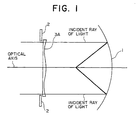
FIG. 1 is a view showing a structure of an imaging optical
system according to embodiment 1 of the present invention.
FIG. 2 is an enlarged view showing an aberration correcting
plate of the imaging optical system according to the embodiment
1 of the present invention.
FIG. 3 is a view showing an aberration correcting plate of
an imaging optical system according to embodiment 2 of the present
invention.
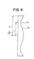
FIG. 4 is a view showing another aberration correcting plate
of the imaging optical system according to the embodiment 2 of the
present invention.
FIG. 5 is a view showing a structure of an imaging optical
system according to embodiment 3 of the present invention.
FIG. 6 is a view showing a structure of an imaging optical
system according to embodiment 4 of the present invention.
FIG. 7 is a view showing an aberration correcting plate of
an imaging optical system according to embodiment 5 of the present
invention.
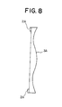
FIG. 8 is a view showing a structure of an imaging optical
system according to embodiment 7 of the present invention.
FIG. 9 is a view showing a structure of a conventional imaging
optical system.
Best Mode for Carrying out the Invention
Hereinafter, embodiments of the present invention each will
be described with reference to the drawings.
Embodiment 1
An imaging optical system according to embodiment 1 of the
present invention will be described with reference to the drawings.
FIG. 1 is a view showing the structure of the imaging optical system
according to the embodiment 1 of the present invention. Note that
the same characters in the respective drawings designate the same
or like portions.
In FIG. 1, reference numeral 1 designates a spherical
reflecting mirror which images incident rays of light from an object.
Reference numeral 2 designates an aperture diaphragm which is
disposed at the center of curvature of the reflecting mirror 1.
Reference numeral 3A designates a circular aberration correcting
plate which is disposed near the aperture diaphragm 2.
FIG. 2 is an enlarged view of the aberration correcting plate
3A. In order to eliminate spherical aberration produced in the
reflecting mirror 2, a side of the aberration correcting plate 3A
has an aspherical shape, and the other side is a flat surface. A
similar effect can be obtained even if the aspherical shape is
arranged at a object side or an image side.
In FIG. 2, reference numeral 4 designates a unevenness portion
having an effect of eliminating the spherical aberration and having
the aspherical shape. Reference numeral 5 designates a substrate
portion which has such a thickness that the aberration correcting
plate 3A has satisfactory strength. Hereinafter, when the term of
surface shape appears, it indicates the aspherical surface shape.
The above optical system uses such a shape that when the
surface shape of the aberration correcting plate 3A is approximated
as shown in an expression (2) mentioned below, a parameter k becomes
almost 1.
z = A(y4 - kh2y2)
Where, "z" designates a coordinate in a direction of an
optical axis; "A", a constant determined by a correction amount
for eliminating the spherical aberration; "y", a coordinate in a
direction vertical to the optical axis; and "h", a radius of the
aperture diaphragm.
When the thickness of the unevenness of the surface shape of
the aberration correcting plate A3 is d, since the following
expression (3) is obtained from the above expression (2), eventually,
it becomes thinnest at k = 1, and the thickness dmin of the unevenness
of the surface shape of the aberration correcting plate 3A at that
time is expressed by the following expression (4).
d = max{Ah4(k2/4), Ah4((k - 2)2/4)}
dmin = Ah4/4
When an absorption coefficient of a material is α,
transmittance T of the unevenness of the aberration correcting plate
3A is expressed by the following expression (5). Here, an
integration range is 0 to h.
From the above expression (5), the transmittance T becomes
maximum at k = 1, irrespective of the absorption coefficient α.
That is, when the surface shape in which k = 1 is obtained is used
for the aberration correcting plate 3A, it is possible to form the
aberration correcting plate 3A which has the smallest thickness
and maximum transmittance T.
Since the transmittance T can be made high by using the
aberration correcting plate 3A having the shape as described above,
a material having a relatively large absorption coefficient α can
be used as a material of the aberration correcting plate 3A.
For example, although plastic or silicon is a material by
which a lens can be produced at low cost, the absorption coefficient
α is large as an optical material for infrared rays, that is, the
transmittance T is low as compared with the transmittance T of
germanium of a conventional material, so that it is not generally
used. However, when a drop of contrast due to the transmittance
is suppressed to the minimum by forming the surface shape of k =
1, plastic or silicon can be used as an inexpensive material of
the aberration correcting plate 3A. Note that, since the thickness
of the unevenness also becomes minimum, the influence of the spatial
distribution of transmittance on the picture quality is also low.
Note that, that the unevenness of the aberration correcting
plate 3A is small widens the selection of producing methods. For
example, in the case where the surface shape of the aberration
correcting plate 3A is produced by use of cutting or polishing,
when the unevenness of the surface shape is small, naturally, a
working amount is also small, so that a working time is also short
and production can be made at low cost.
A working method which can not be applied to a surface shape
having large unevenness, can also be applied. For example, it also
becomes possible to make such a working that after plastic thermally
melted into liquid is coated on a metal substrate, it is solidified
and molded. Alternatively, it also becomes possible to process a
hard material such as silicon by using etching to make a shape.
Alternatively, it also becomes possible to form a shape by using
deposition.
Note that the parameter k is expressed by the following
expression (7) with respect to the surface shape expressed by an
expression (6), using arbitrary coefficients a, b, c1, c2, ···.
An imaging optical system according to embodiment 2 of the
present invention will be described with reference to the drawings.
FIG. 3 is a view showing a section of an aberration correcting plate
of the imaging optical system according to the embodiment 2 of the
present invention. FIG. 4 is a view showing a section of another
aberration correcting plate of the imaging optical system according
to the embodiment 2 of the present invention.
As shown in FIG. 3, a thickness da of the center of a center
portion 3a of an aberration correcting plate 3B is made almost
identical to a thickness db of a peripheral portion 3b, so that an
equivalent to the aberration correcting plate 3A of the embodiment
1 can be realized.
Note that, as shown in FIG. 4, a neutral band 3c is placed
at a position of a radius h/√2 with respect to a radius h of an
aberration correcting plate 3C, so that an equivalent to the
aberration correcting plate 3A of the embodiment 1 can be realized.
Note that the radius of the aberration correcting plate 3C is an
effective radius of the aberration correcting plate 3C and is equal
to a radius h of the aperture diaphragm 2.
Note that the "neutral band" is points on an aspherical
surface of the aberration correcting plate 3C and is points where
a contact plane other than the center intersects with the optical
axis vertically. An angle of a ray of light passing through the
neutral band 3c is not changed before and after the incidence thereof
on the aberration correcting plate 3C.
In the aberration correcting plate 3A of the embodiment 1 and
the aberration correcting plates 3B and 3C of the embodiment 2,
the surface shape is made to have such a shape that the spherical
aberration produced by the reflecting mirror 1 is eliminated.
However, when such a shape is made that the spherical aberration
slightly remains, that is, for example, in the aberration correcting
plate 3A, for example, the constant A in the expression (2) is made
small to lessen the unevenness of the aspherical shape, and when
the surface shape of the aberration correcting plate is made to
have such a shape that the spherical aberration slightly remains,
the focal depth can be lengthened. By lengthening the focal depth,
the influence of curvature of field becomes low, and a wide angle
optical system can be used even for a flat image detector.
Embodiment 3
An imaging optical system according to embodiment 3 will be
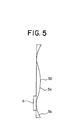
described with reference to the drawing. FIG. 5 is a view showing
an aberration correcting plate of the imaging optical system
according to the embodiment 3 of the present invention.
In FIG. 5, reference numeral 6 designates a holding member
of, for example, a plate shape, which fixes a center portion 3a
of an aberration correcting plate 3D to a peripheral portion 3b.
Other structural parts are the same as those of the embodiment 1.
Note that the holding member 6 may have any shape.
Although the thickness of the aberration correcting plate 3A
in the embodiment 1 is determined by the sum of the unevenness
portion 4 and the substrate portion 5, in the case where a material
having low transmittance is used for the aberration correcting plate
3D, as it becomes thin, its transmittance naturally becomes high,
which is preferable. Since the thickness of the unevenness portion
4 is determined by the aspherical shape, it can not be freely set.
On the other hand, since the thickness of the substrate
portion 5 is determined by the strength, when the center portion
3a is supported by, for example, the holding member 6 as shown in
FIG. 5, the substrate portion 5 can be made considerably thin or
can be completely removed.
Further, if the produced aberration is within an allowable
range, a structure can also be adopted in which a hole is bored
in the neutral band of the aberration correcting plate 3D.
In the example shown in FIG. 5, although the holding member
6 is provided at only one place, in the case where the strength
is required, it may be fixed, for example, radially at several places .
Alternatively, a mesh shape holding member may be used.
Note that, in order to decrease the number of parts and
operation steps, the aberration correcting plate 3D and the holding
member 6 may be integrally molded.
Alternatively, in order to suppress the diffraction produced
by the holding member 6 or a drop in transmittance, the holding
member 6 may be made thin by using a material having strength, for
example, metal.
Embodiment 4
An imaging optical system according to embodiment 4 will be
described with reference to the drawing. FIG. 6 is a view showing
a structure of the imaging optical system according to the
embodiment 4 of the present invention.
In FIG. 6, reference numeral 7 designates a circular holding
flat plate to which an aberration correcting plate 3D is bonded
and is fixed, and its transmittance is high to a wavelength of light
used for a camera. Other structural parts are the same as those
of the embodiment 1.
In the embodiment 3, although the holding member 6 is used
for obtaining satisfactory strength to the aberration correcting
plate 3D, in this embodiment 4, the strength is obtained by bonding
the aberration correcting plate 3D to the holding flat plate 7
transparent to the wavelength of light used.
Embodiment 5
An imaging optical system according to embodiment 5 will be
described with reference to the drawing. FIG. 7 is a view showing
an aberration correcting plate of the imaging optical system
according to the embodiment 5 of the present invention.
In the respective embodiments mentioned above, although only
one side of each of the aberration correcting plates 3A to 3D is
made to have the aspherical shape, as shown in FIG. 7, even if both
sides are made to have the aspherical shape, a similar effect can
be obtained. In this case, a neutral band of an aberration
correcting plate 3E indicates a place where the plate thickness
is thinnest. The parameter k can be obtained by approximating the
thickness of the aberration correcting plate by a quartic function
expressed by the following expression (8).
z = A(y2 - kh2/2)2
Embodiment 6
In the respective embodiments mentioned above, although the
reflecting mirror 1 is used for imaging incident rays of light from
an object, any optical element may be used as long as it has a similar
imaging function (light-concentrating function).
For example, a refraction optical system, a diffraction lens,
or a Fresnel lens can also be used.
Further, the number of elements is not limited to one, but
any number of elements may be used as long as the imaging function
(light-concentrating function) is obtained as a whole.
Embodiment 7
An imaging optical system according to embodiment 7 of the
present invention will be described with reference to the drawing.
FIG. 8 is a view showing an aberration correcting plate of the
imaging optical system according to the embodiment 7 of the present
invention.
In the respective embodiments mentioned above, although the
aperture diaphragm 2 and each of the aberration correcting plates
3A to 3E are structured as separate parts, the aperture diaphragm
2 and each of the aberration correcting plates 3A to 3E may be
integrated by providing a light shielding portion 2A at a peripheral
portion of each of the aberration correcting plates 3A to 3E.
Such a structure can be realized by, for example, applying
opaque black paint to the peripheral portion of each of the
aberration correcting plates 3A to 3E.
According to such a structure, since the aperture diaphragm
2 as a separate part can be omitted, the number of parts can be
reduced, and the production steps of the parts and assembling steps
can be decreased.
Industrial Applicability
An imaging optical system according to claim 1 of the present
invention includes, as described above, an optical element having
an imaging function as a whole and for imaging incident rays of
light from an object, an aperture diaphragm disposed at the center
of curvature of the optical element, and an aberration correcting
plate disposed near the aperture diaphragm, having at least one
surface of an aspherical shape, and for eliminating spherical
aberration produced in the optical element, in which when a
coordinate in a direction of an optical axis is z, a coordinate
in a direction vertical to the optical axis is y, a radius of the
aperture diaphragm is h, and a constant determined by a correction
amount for eliminating the spherical aberration is A, and when the
aspherical shape of the aberration correcting plate is approximated
by a quartic function, z = A(y*y*y*y - k*h*h*y*y), a parameter k
is almost 1, whereby there are obtained such effects that the
unevenness of the aspherical shape can be made small with respect
to the Schmidt type optical system, and the transmittance can be
made high.
An imaging optical system according to claim 2 of the present
invention includes, as described above, an optical element having
an imaging function as a whole and for imaging incident rays of
light from an object, an aperture diaphragm disposed at the center
of curvature of the optical element, and an aberration correcting
plate disposed near the aperture diaphragm, having at least one
surface of an aspherical shape, and for eliminating spherical
aberration produced in the optical element, in which a thickness
of a peripheral portion of the aberration correcting plate is almost
identical to that of its center portion, whereby there are obtained
such effects that the unevenness of the aspherical shape can be
made small with respect to the Schmidt type optical system, and
the transmittance can be made high.
An imaging optical system according to claim 3 of the present
invention includes, as described above, an optical element having
an imaging function as a whole and for imaging incident rays of
light from an object, an aperture diaphragm disposed at the center
of curvature of the optical element, and an aberration correcting
plate disposed near the aperture diaphragm, having at least one
surface of an aspherical shape, and for eliminating spherical
aberration produced in the optical element, in which when a radius
of the aberration correcting plate is h, a radius of a neutral band
of the aberration correcting plate is almost h/√2, whereby there
are obtained such effects that the unevenness of the aspherical
shape can be made small with respect to the Schmidt type optical
system, and the transmittance can be made high.
According to an imaging optical system of claim 4 of the
present invention, as described, in the aberration correcting plate,
the aspherical shape is such a shape that the aberration slightly
remains, whereby there is obtained an effect that the influence
of curvature of field can be made low.
According to an imaging optical system of claim 5 of the
present invention, as described above, the aberration correcting
plate is formed from a material having low transmittance, whereby
there is obtained such an effect that the unevenness of the
aspherical shape can be made small with respect to the Schmidt type
optical system.
According to an imaging optical system of claim 6 of the
present invention, as described above, the material having the low
transmittance is plastic, whereby there is obtained such an effect
that the unevenness of the aspherical shape can be made small with
respect to the Schmidt type optical system.
According to an imaging optical system of claim 7 of the
present invention, as described above, the material having the low
transmittance is silicon, whereby there is obtained such an effect
that the unevenness of the aspherical shape can be made small with
respect to the Schmidt type optical system.
According to an imaging optical system of claim 8 of the
present invention, as described above, in the aberration correcting
plate, a neutral band between its center portion and its peripheral
portion is considerably thin or a hole, and a holding member for
joining the center portion to the peripheral portion is further
provided, whereby there is obtained such an effect that the
unevenness of the aspherical shape can be made small with respect
to the Schmidt type optical system.
According to an imaging optical system of claim 9 of the
present invention, as described above, the aberration correcting
plate is molded integrally with the holding member, whereby there
is obtained such an effect that the number of parts can be reduced.
According to an imaging optical system of claim 10 of the
present invention, as described above, the holding member is metal,
whereby there is obtained such an effect that the unevenness of
the aspherical shape can be made small with respect to the Schmidt
type optical system.
According to an imaging optical system of claim 11 of the
present invention, as described above, the aberration correcting
plate is bonded to a holding flat plate having high transmittance
to a wavelength of light used, whereby there is obtained such an
effect that the unevenness of the aspherical shape can be made small
with respect to the Schmidt type optical system.
According to an imaging optical system of claim 12 of the
present invention, as described above, the aberration correcting
plate is integrated with the aperture diaphragm, whereby there is
obtained such an effect that the number of parts can be reduced.
According to an imaging optical system of claim 13 of the
present invention, as described above, only one side of the
aberration correcting plate is made to have the aspherical shape,
whereby there are obtained such effects that the unevenness of the
aspherical shape can be made small with respect to the Schmidt type
optical system, and the transmittance can be made high.
According to an imaging optical system of claim 14 of the
present invention, as described above, both sides of the aberration
correcting plate are made to have the aspherical shape, whereby
there are obtained such effects that the unevenness of the
aspherical shape can be made small with respect to the Schmidt type
optical system, and the transmittance can be made high.