EP1195210A2 - Process and device for direct chill casting - Google Patents
Process and device for direct chill casting Download PDFInfo
- Publication number
- EP1195210A2 EP1195210A2 EP01308552A EP01308552A EP1195210A2 EP 1195210 A2 EP1195210 A2 EP 1195210A2 EP 01308552 A EP01308552 A EP 01308552A EP 01308552 A EP01308552 A EP 01308552A EP 1195210 A2 EP1195210 A2 EP 1195210A2
- Authority
- EP
- European Patent Office
- Prior art keywords
- mould
- coolant
- castpart
- outlet
- emerging
- Prior art date
- Legal status (The legal status is an assumption and is not a legal conclusion. Google has not performed a legal analysis and makes no representation as to the accuracy of the status listed.)
- Withdrawn
Links
Images


Classifications
-
- B—PERFORMING OPERATIONS; TRANSPORTING
- B22—CASTING; POWDER METALLURGY
- B22D—CASTING OF METALS; CASTING OF OTHER SUBSTANCES BY THE SAME PROCESSES OR DEVICES
- B22D11/00—Continuous casting of metals, i.e. casting in indefinite lengths
- B22D11/04—Continuous casting of metals, i.e. casting in indefinite lengths into open-ended moulds
- B22D11/049—Continuous casting of metals, i.e. casting in indefinite lengths into open-ended moulds for direct chill casting, e.g. electromagnetic casting
Definitions
- This invention relates to a system for use in a continuous cast mold in which coolant is applied to a castpart emerging from a mold cavity, and discloses a system which controls the flow of coolant back toward the mold cavity. More particularly, this invention relates to the creation of a forced gas barrier or knife, which prevents coolant from moving against the direction of the movement of the emerging castpart and back toward the mold cavity.
- coolant While coolant is generally directed, applied or sprayed in one or more jets onto the emerging castpart, the coolant has a tendency to creep or flow back toward the mold cavity. This may be referred to as a capillary action of the coolant, as it moves, flows or creeps toward the mold cavity or mold cavity inlet.
- the ability (or inability) to sufficiently control the flow of the coolant back toward the mold cavity has also imposed certain limitations in the utilization of other more efficient casting techniques. For example, applying the coolant at an approximate ninety degree angle to the surface of the emerging castpart may increase the efficiency of the cooling. However most coolant is applied at an angle substantially less than ninety degrees due to the inability to control or prevent the flow of the coolant back toward the mold cavity.
- This invention utilizes a fluid, preferably a gas, even more preferably, air, to create pressure, force, and/or a barrier, baffle or knife which prevents the coolant from flowing, creeping or moving back toward the mold cavity inlet.
- a fluid preferably a gas, even more preferably, air
- This invention is not however limited to the fluid being a gas, but instead it may be other types of fluids such as ethylyn glycol (a non-explosive fluid).
- control system provided by this invention will allow for an angle between the coolant stream and the metal surface of up to ninety degrees or more, including up to one hundred twenty degrees. This will allow for more efficient and effective direct-cooled metal casting.
- references herein are generally to the continuous casting if ingot-shaped and billet-shaped castparts, this invention is certainly not limited to any particular shape or configuration of castpart, but instead applies to all such shapes, including exotic and unique shapes in addition to the more traditional billets and ingots.
- this invention may be applied in different embodiments to differently configured continuous casting molds and devices, including vertical molds, horizontal molds, and molds at any other possible angle.
- This invention is particularly well suited to allow continuous casting and the utilization of coolant at numerous different angles for the casting, as the invention better provides for the control and/or prevention of the movement of the fluid back toward the mold cavity.
- This invention will be important in allowing other directional castings to be utilized without fear of the coolant moving, creeping, or flowing back toward or into the mold cavity.
- Figure 1 is similar to Figure 10 from U.S. Patent No. 5,582,230 and illustrates a typical cross-section and schematic of the interface between the coolant discharge and the emerging castpart in a continuous casting mold.
- Figure 1 illustrates emerging castpart 1, mold ring 2 supported within framework 3, first coolant discharge aperture 4, and second coolant discharge aperture 5.
- first coolant discharge aperture 4 contacts the emerging castpart at or about target zone 6.
- the coolant then typically moves in the direction the emerging castpart is moving, and also splashes as additional coolant is discharged.
- a force is imparted on coolant away from the mold inlet, this not only includes imparting a force on the coolant, but may also include imparting a force only on a coolant vapor and/or on the coolant.
- Figure 1 further illustrates first coolant reservoir 8 and second coolant reservoir 9 which supply the coolant for first coolant discharge aperture 4 and second coolant discharge aperture 5, respectively.
- Figure 2 is a perspective view of one example of a mold framework 20 shaped to produce rectangular or ingot-shaped castparts or cast formats.
- the mold outlet cavity side 21 and the mold intlet cavity side 22 of the framework are shown, and molten metal would generally be provided or made available through mold inlet cavity 21, and would exit through mold outlet cavity 22. It is generally at the mold outlet cavity 22 where coolant is sprayed on or directed to the emerging castpart.
- the general manufacture and use of such a mold framework 20 is well known by those of ordinary skill in the art and will not be described in further detail. Furthermore, a more detailed description of such a framework is provided in U.S. Patent No. 5,582,230, which has previously been incorporated herein by reference.
- Figure 3 is a bottom view of the example of the typical ingot-shaped mold framework as illustrated in Figure 2, and is a view from the outlet cavity side of the mold framework 20.
- the inner perimeter 24 of the mold framework is also shown in Figure 3, and generally defining what is referred to as an ingot shape.
- Figure 4 is an exemplary elevation view, part schematic, part cross- sectional, of a continuous casting mold which casts round or billet shaped castparts or cast formats.
- Figure 4 illustrates one of the several other possible environments for the utilization of the invention described herein.
- Figure 4 illustrates mold distribution trough 30 which is generally composed of refractory material and which is a distribution trough through which molten metal is provided to mold or mold framework 31.
- Mold inlet or mold inlet cavity 32 is where molten metal is received within and by mold ring 34
- mold outlet cavity 35 is where the emerging billet or emerging castpart exits the mold or mold cavity.
- Outline 36 illustrates a billet-shaped castpart as it would otherwise exit the mold.
- mold inlet or mold inlet cavity as used in the claims are intended to be used as a direction towards which it is desired to prevent the coolant from flowing, which is generally in the opposite direction of the flow of the molten metal.
- This invention is not limited to a vertical or horizontal application, but would apply to situations where the mold is upside down from the current typical mold orientation so that the cast part is emerging in an upward direction.
- Coolant discharge apertures 38 are also illustrated and show a relative location of the coolant discharge relative to the mold cavity 39 and mold outlet cavity 35.
- Figure 4 illustrates a general configuration of how molten metal would be fed into the mold inlet cavity 32, proceed to mold cavity 39 surrounded by mold rings 34, and then emerging through mold outlet cavity 35, while coolant is sprayed or discharged thereon.
- Figure 5 is an illustration of one embodiment of this invention wherein the system for preventing the flow of the coolant back toward the mold cavity is combined with a first coolant discharge aperture 50 and a second coolant discharge aperture 51.
- the first coolant discharge aperture 50 discharges coolant 52 to contact the emerging castpart 53 on or about the target zone 54.
- mold ring 55 Also illustrated in Figure 5 are mold ring 55, first coolant reservoir 56, and second coolant reservoir 57.
- This invention provides a baffle fluid which is preferably a gas, and more particularly, preferably air, to impart a force on a coolant adjacent a castpart surface in a direction away from the mold inlet.
- a baffle fluid which is preferably a gas, and more particularly, preferably air, to impart a force on a coolant adjacent a castpart surface in a direction away from the mold inlet.
- gas is just one of the baffle fluids which may used in an embodiment of this invention, with others being equally usable within the contemplation of the invention (such as momentum bearing fluids, fluids which have an affinity to water vapor).
- baffle fluid apertures may be located in any one of a number of different positions or components within the contemplation of the various embodiments of this invention, such as in the bottom block, in the graphite, or in a separate baffle body structure.
- Figure 5 illustrates gas feed aperture 60 which feeds the one or more gas discharge apertures 61.
- the discharged gas 62 (preferably air) imparts a force on the coolant and on the outer perimeter surface 53a of the emerging castpart 53 to prevent the coolant 52 from moving back toward the mold cavity. It will be appreciated by those of ordinary skill in the art that there are numerous different configurations for gas discharge apertures which would create such a gas force on the coolant 52 around the outer perimeter 53a of the castpart 53, to prevent the coolant 52 from traveling back toward the mold cavity.
- Figure 6 is a perspective view of a short portion of an embodiment of a mold framework 70 of this invention and illustrates a plurality of gas discharge apertures 71, a plurality of first coolant discharge apertures 72, and a plurality of second coolant discharge apertures 73.
- Figure 6 would be representative of an embodiment similar to that shown in Figure 5 and further illustrates gas discharge feed aperture 75, first coolant feed discharge aperture 76, and second coolant feed discharge aperture 77.
- this coolant control system will be used to effectively mold exotic and non-symmetrical castparts, and the particular controls provided by this system will allow unique castpart outer perimeter shapes (and casting angles) through the placement of gas discharge apertures around the castpart outer perimeter, to prevent the coolant from traveling or flowing back toward the mold cavity.
- Figure 7 is a cross-sectional view of the mold framework 70 shown in Figure 6 and illustrates gas discharge feed aperture 75, first coolant feed discharge aperture 76 and second coolant feed discharge aperture 77.
- the gas discharge aperture 71, the first coolant discharge aperture 72, and the second coolant discharge aperture 73 are also illustrated in Figure 6.
- Figure 7 also illustrates a few examples of angles at which the various discharge apertures may be with respect to the interior perimeter of the mold framework 70, which is the same approximate angle to the outer perimeter surface of the emerging castpart (which will approximately abut against the interior perimeter surface of mold framework 70).
- Angle 78 is the angle between the gas discharge aperture 71 and the mold framework interior perimeter surface 70, and is intended to represent the angle at which the gas is discharged relative to the outer perimeter surface of the emerging castpart. As will be appreciated by those of ordinary skill in the art, angle 78 need not be any particular magnitude within the contemplation of this invention, but instead may range from zero degrees to eighty or ninety degrees, with approximately fifteen to twenty degrees being preferred.
- Angle 79 represents the angle between the second coolant discharge aperture 73 and the outer surface of the emerging castpart
- angle 80 represents the angle between the first coolant discharge apertures 72 and the outer perimeter surface of the emerging castpart.
- Figure 8 is another embodiment or illustration, part cross-sectional and part schematic view, of an embodiment of this invention in which the coolant discharge aperture is at an approximate ninety (90) degree angle relative to the interior perimeter surface of the mold framework and with respect to the outer perimeter surface of the emerging castpart.
- Figure 8 illustrates mold framework 80, coolant discharge aperture 81 approximately perpendicular to the outer perimeter surface 86 of the emerging castpart 85, gas discharge feed aperture 82, gas discharge aperture 83, coolant 84, and emerging castpart 85.
- This invention is particularly well suited to allow the use of this more effective cooling angle (i.e. to approximately ninety (90) degrees or even one hundred five (105) degrees or beyond), and configuration to be utilized, since this invention provides for the more effective prevention of the coolant 84 moving or flowing back toward mold cavity 86.
- this more effective cooling angle i.e. to approximately ninety (90) degrees or even one hundred five (105) degrees or beyond
- the discharged gas 93 is shown preventing the coolant 84 from moving back toward the mold cavity 86 by imparting a force or creating a gas barrier or gas knife between the mold cavity 86 and the coolant.
- the gas barrier is generally created around the outer perimeter surface 86 of the emerging castpart 85.
- Figure 9 is a close-up detail of the target zone 90 where coolant stream 84 contacts emerging castpart 85.
- Gas discharge aperture 83 discharges a stream of forced gas 93 which imparts a force on emerging castpart 85 and on the coolant 84 to prevent the coolant from creeping or flowing back toward the mold cavity.
- Emerging castpart 85 is moving in the direction shown by arrow 87.
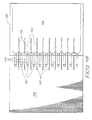
- Figure 10 shows a schematic view of mold framework 100, emerging castpart 105, coolant discharge apertures 101 providing coolant discharge streams 108 which impact or contact emerging castpart 105 approximately at target zones 103.
- gas discharge apertures 102 are provided between coolant discharge apertures 101 to more effectively impart a force on the coolant between the target zones 103. This is the preferred method of imparting a gas force on the coolant to control it and prevent it from moving back toward the mold cavity.
- Coolant 106 is shown on emerging castpart 105 in Figure 10.
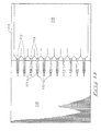
- Figure 11 illustrates another embodiment of this invention, only wherein the gas discharge apertures 112 in the mold framework 100 provide the force or discharge gas approximately at the target zones 113. Coolant 116 is also shown on emerging castpart 115. While this is not a preferred embodiment, it is an optional one contemplated by this invention.
- gas discharge apertures 112 may be extended or more precisely placed by using hollow pin type apertures extending from the mold framework 110.
- Figure 12 is a perspective schematic view of the embodiment of the invention illustrated in Figure 11 and shows mold framework 120, coolant streams 121 being discharged through coolant apertures (not shown) in mold framework 120. Gas discharge apertures 123 are configured to impart the gas force at approximately the target zones 122. Coolant 125 is also shown on emerging castpart 126.
- Figure 13 is a schematic of the configuration shown in Figure 10 of discharge coolant streams 108 being discharged from mold framework 100 and gas discharge apertures 102 being positioned between the target zones which coolant streams 108 are hitting. Coolant 106 is shown on emerging castpart 105.
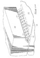
- Figure 14 illustrates mold framework 150, gas discharge slit aperture 151, first coolant discharge apertures 152, second coolant discharge apertures 153, first coolant feed discharge aperture 156, second coolant feed discharge aperture 157, and gas discharge feed aperture 155.
- Figure 14 shows an embodiment wherein a slit is used to form an air curtain or to impart the gas force instead of a plurality of individual elliptical- or circular-shaped apertures (as shown in prior embodiments).
- the invention may be considered a baffle for use in a continuous cast mold with a mold inlet, a mold outlet and a mold outlet perimeter, the mold further providing for a coolant to be applied to a castpart emerging from the mold, the baffle preventing the flow of the coolant back toward a mold inlet, the baffle comprising: a baffle body structure; one or more baffle fluid apertures in the baffle body structure and around the mold outlet perimeter, the one or more baffle fluid apertures disposed to impart forced baffle fluid on coolant which is on or adjacent a castpart surface emerging from the mold, and in a direction away from the mold inlet.
- the baffle body structure may be considered the graphite around the mold outlet perimeter, the bottom cover or any other structure which wholly or partially covers the mold outlet perimeter sufficiently to create the baffle.
Abstract
Description
- This invention relates to a system for use in a continuous cast mold in which coolant is applied to a castpart emerging from a mold cavity, and discloses a system which controls the flow of coolant back toward the mold cavity. More particularly, this invention relates to the creation of a forced gas barrier or knife, which prevents coolant from moving against the direction of the movement of the emerging castpart and back toward the mold cavity.
- Direct cooled metal casting processes and apparatuses have been known for many years, such as that disclosed in U.S. Patent No. 5,582,230 for a "Direct Cooled Metal Casting Process and Apparatus", which is incorporated herein by this reference as though fully set forth herein.
- While coolant is generally directed, applied or sprayed in one or more jets onto the emerging castpart, the coolant has a tendency to creep or flow back toward the mold cavity. This may be referred to as a capillary action of the coolant, as it moves, flows or creeps toward the mold cavity or mold cavity inlet.
- It is desirable in the industry to control the placement and location of the coolant and to prevent the coolant from moving, flowing or creeping back toward the mold cavity.
- There have been prior uses of discharge jets and other coolant manipulation techniques to affect the cooling of the emerging ingot and to more precisely control the location and magnitude of cooling, as more fully disclosed in U.S. Patent No. 5,582,230. These techniques may also help control the tendency of the coolant to flow back toward the mold cavity. However, using coolant to avoid having coolant flow back toward the mold cavity is not as effective as the present invention.
- The ability (or inability) to sufficiently control the flow of the coolant back toward the mold cavity has also imposed certain limitations in the utilization of other more efficient casting techniques. For example, applying the coolant at an approximate ninety degree angle to the surface of the emerging castpart may increase the efficiency of the cooling. However most coolant is applied at an angle substantially less than ninety degrees due to the inability to control or prevent the flow of the coolant back toward the mold cavity.
- The inability to sufficiently control the flow of the coolant back toward the mold cavity has also presented limitations on the ability to change the orientation of the mold without concern over the coolant working its way back toward the mold cavity. For instance in a vertical mold, the mold cavity is vertically above the location where coolant is applied to the emerging castpart and gravity therefore assists in keeping the coolant from flowing back toward the mold cavity. In horizontal molds gravity does not provide the same assistance and controlling the flow of the coolant becomes more important. It is therefore an object of this invention to provide a direct cooled metal casting control system which better controls and prevents the coolant from flowing, creeping or moving back toward the mold cavity. This invention utilizes a fluid, preferably a gas, even more preferably, air, to create pressure, force, and/or a barrier, baffle or knife which prevents the coolant from flowing, creeping or moving back toward the mold cavity inlet. This invention is not however limited to the fluid being a gas, but instead it may be other types of fluids such as ethylyn glycol (a non-explosive fluid).
- The control system provided by this invention will allow for an angle between the coolant stream and the metal surface of up to ninety degrees or more, including up to one hundred twenty degrees. This will allow for more efficient and effective direct-cooled metal casting.
- Preferred embodiments of the invention are described below with reference to the accompanying drawings, which are briefly described below.
- Figure 1 is a part schematic, part cross-sectional view of a prior art mold portion as disclosed in U.S. Patent No. 5,582,230, illustrating two coolant discharge apertures contacting the emerging castpart;
- Figure 2 is a perspective view of an example of a typical ingot shaped mold framework and mold cavity;
- Figure 3 is a bottom view of the example of the typical ingot shaped mold framework and mold cavity illustrated in Figure 2;
- Figure 4 is an exemplary elevation part schematic, part cross-sectional view of a mold for casting billets, and illustrates one alternative environment for the use of the invention;
- Figure 5 is a part schematic, part cross-sectional view of one embodiment of a mold utilizing the system provided by this invention, illustrating two coolant discharge apertures contacting the emerging metal castpart, and further illustrates a gas control system and aperture imparting a force on the coolant away from the mold cavity;
- Figure 6 is a perspective view of an exemplary short section of an embodiment of a mold framework, illustrating the relative configuration of the multiple coolant apertures and of the apertures for introducing gas to keep the coolant from moving back toward the mold cavity;
- Figure 7 is a side view of the portion of the mold shown in Figure 6 and illustrates an embodiment of this invention with the gas discharge apertures;
- Figure 8 is a part cross-sectional and part schematic view of an embodiment of this invention wherein the coolant is discharged at an angle of approximately ninety degrees relative to the outer perimeter surface of the emerging castpart;
- Figure 9 is the detail view from Figure 8, and illustrates the forced gas imparting a force on the coolant and preventing it from moving back toward the mold cavity;
- Figure 10 is an elevation view schematic of an embodiment of this invention wherein the gas is introduced between the target zones of adjacent coolant aperture discharges;
- Figure 11 is an elevation schematic view of one embodiment of this invention wherein the gas is introduced at or near the target zones for the coolant discharged on the emerging metal;
- Figure 12 is a perspective schematic illustrating the coolant as discharged and the introduction of gas at or near the coolant target zone;
- Figure 13 is a perspective schematic view of the embodiment of this invention wherein the gas is introduced between target zones of adjacent coolant discharges; and
- Figure 14is a perspective view of a section of a mold framework which has an air slit aperture instead of individual apertures.
-
- Many of the fastening, connection, manufacturing and other means and components utilized in this invention are widely known and used in the field of the invention described, and their exact nature or type is not necessary for an understanding and use of the invention by a person skilled in the art or science; therefore, they will not be discussed in significant detail. Furthermore, the various components shown or described herein for any specific application of this invention can be varied or altered as anticipated by this invention and the practice of a specific application or embodiment of any element may already be widely known or used in the art or by persons skilled in the art or science; therefore, each will not be discussed in significant detail.
- The terms "a", "an", and "the" as used in the claims herein are used in conformance with long-standing claim drafting practice and not in a limiting way. Unless specifically set forth herein, the terms "a", "an", and "the" are not limited to one of such elements, but instead mean "at least one".
- This invention has numerous different embodiments within direct cooled metal casting processes and apparatuses, with only a few being described herein, including the preferred embodiment, as required. One such environment, which is incorporated by reference herein, is U.S. Patent No. 5,582,230, which describes, discloses and illustrates a system for cooling an emerging castpart, and which would help control the backflow of the coolant with a second coolant discharge directed at portions of the coolant from the first coolant discharge.
- Although the references herein are generally to the continuous casting if ingot-shaped and billet-shaped castparts, this invention is certainly not limited to any particular shape or configuration of castpart, but instead applies to all such shapes, including exotic and unique shapes in addition to the more traditional billets and ingots.
- It will further be appreciated that this invention may be applied in different embodiments to differently configured continuous casting molds and devices, including vertical molds, horizontal molds, and molds at any other possible angle. This invention is particularly well suited to allow continuous casting and the utilization of coolant at numerous different angles for the casting, as the invention better provides for the control and/or prevention of the movement of the fluid back toward the mold cavity. This invention will be important in allowing other directional castings to be utilized without fear of the coolant moving, creeping, or flowing back toward or into the mold cavity.
- Figure 1 is similar to Figure 10 from U.S. Patent No. 5,582,230 and illustrates a typical cross-section and schematic of the interface between the coolant discharge and the emerging castpart in a continuous casting mold. Figure 1 illustrates emerging
castpart 1,mold ring 2 supported withinframework 3, first coolant discharge aperture 4, and secondcoolant discharge aperture 5. - The coolant discharged from first coolant discharge aperture 4 contacts the emerging castpart at or about
target zone 6. The coolant then typically moves in the direction the emerging castpart is moving, and also splashes as additional coolant is discharged. - When it is referred to herein that a force is imparted on coolant away from the mold inlet, this not only includes imparting a force on the coolant, but may also include imparting a force only on a coolant vapor and/or on the coolant.
- It will be appreciated by those of ordinary skill in the art that while this invention may be used with one or two coolant discharge apertures, there is no particular number which needs to be used in order to practice the embodiments of this invention. The examples and illustrations shown herein are for illustrative purposes and not in any way to limit the environment or scope of the invention.
- Figure 1 further illustrates
first coolant reservoir 8 and second coolant reservoir 9 which supply the coolant for first coolant discharge aperture 4 and secondcoolant discharge aperture 5, respectively. - There are numerous general and specific configurations for continuous casting molds, which are generally known by those of ordinary skill in the art, and each one will not be described in any significant detail herein.
- Figure 2 is a perspective view of one example of a
mold framework 20 shaped to produce rectangular or ingot-shaped castparts or cast formats. The moldoutlet cavity side 21 and the moldintlet cavity side 22 of the framework are shown, and molten metal would generally be provided or made available throughmold inlet cavity 21, and would exit throughmold outlet cavity 22. It is generally at themold outlet cavity 22 where coolant is sprayed on or directed to the emerging castpart. The general manufacture and use of such amold framework 20 is well known by those of ordinary skill in the art and will not be described in further detail. Furthermore, a more detailed description of such a framework is provided in U.S. Patent No. 5,582,230, which has previously been incorporated herein by reference. - Figure 3 is a bottom view of the example of the typical ingot-shaped mold framework as illustrated in Figure 2, and is a view from the outlet cavity side of the
mold framework 20. Theinner perimeter 24 of the mold framework is also shown in Figure 3, and generally defining what is referred to as an ingot shape. - Figure 4 is an exemplary elevation view, part schematic, part cross- sectional, of a continuous casting mold which casts round or billet shaped castparts or cast formats. Figure 4 illustrates one of the several other possible environments for the utilization of the invention described herein.
- Figure 4 illustrates
mold distribution trough 30 which is generally composed of refractory material and which is a distribution trough through which molten metal is provided to mold ormold framework 31. Mold inlet ormold inlet cavity 32 is where molten metal is received within and bymold ring 34, andmold outlet cavity 35 is where the emerging billet or emerging castpart exits the mold or mold cavity.Outline 36 illustrates a billet-shaped castpart as it would otherwise exit the mold. - The terms mold inlet or mold inlet cavity as used in the claims are intended to be used as a direction towards which it is desired to prevent the coolant from flowing, which is generally in the opposite direction of the flow of the molten metal. This invention is not limited to a vertical or horizontal application, but would apply to situations where the mold is upside down from the current typical mold orientation so that the cast part is emerging in an upward direction.
-
Coolant discharge apertures 38 are also illustrated and show a relative location of the coolant discharge relative to themold cavity 39 andmold outlet cavity 35. Figure 4 illustrates a general configuration of how molten metal would be fed into themold inlet cavity 32, proceed to moldcavity 39 surrounded by mold rings 34, and then emerging throughmold outlet cavity 35, while coolant is sprayed or discharged thereon. - Figure 5 is an illustration of one embodiment of this invention wherein the system for preventing the flow of the coolant back toward the mold cavity is combined with a first
coolant discharge aperture 50 and a secondcoolant discharge aperture 51. The firstcoolant discharge aperture 50discharges coolant 52 to contact the emergingcastpart 53 on or about thetarget zone 54. Also illustrated in Figure 5 aremold ring 55,first coolant reservoir 56, andsecond coolant reservoir 57. - This invention provides a baffle fluid which is preferably a gas, and more particularly, preferably air, to impart a force on a coolant adjacent a castpart surface in a direction away from the mold inlet. This creates a baffle of sort between the mold inlet and the target zone for the coolant. Although the term gas is used throughout, it is to be understood that a gas is just one of the baffle fluids which may used in an embodiment of this invention, with others being equally usable within the contemplation of the invention (such as momentum bearing fluids, fluids which have an affinity to water vapor).
- It will also be appreciated by those of ordinary skill in the art that the baffle fluid apertures may be located in any one of a number of different positions or components within the contemplation of the various embodiments of this invention, such as in the bottom block, in the graphite, or in a separate baffle body structure.
- Figure 5 illustrates
gas feed aperture 60 which feeds the one or moregas discharge apertures 61. As can be seen in Figure 5, the discharged gas 62 (preferably air) imparts a force on the coolant and on theouter perimeter surface 53a of the emergingcastpart 53 to prevent thecoolant 52 from moving back toward the mold cavity. It will be appreciated by those of ordinary skill in the art that there are numerous different configurations for gas discharge apertures which would create such a gas force on thecoolant 52 around theouter perimeter 53a of thecastpart 53, to prevent thecoolant 52 from traveling back toward the mold cavity. - Figure 6 is a perspective view of a short portion of an embodiment of a
mold framework 70 of this invention and illustrates a plurality ofgas discharge apertures 71, a plurality of firstcoolant discharge apertures 72, and a plurality of secondcoolant discharge apertures 73. Figure 6 would be representative of an embodiment similar to that shown in Figure 5 and further illustrates gasdischarge feed aperture 75, first coolantfeed discharge aperture 76, and second coolantfeed discharge aperture 77. - It is contemplated by this invention that there will be embodiments wherein this coolant control system will be used to effectively mold exotic and non-symmetrical castparts, and the particular controls provided by this system will allow unique castpart outer perimeter shapes (and casting angles) through the placement of gas discharge apertures around the castpart outer perimeter, to prevent the coolant from traveling or flowing back toward the mold cavity.
- Figure 7 is a cross-sectional view of the
mold framework 70 shown in Figure 6 and illustrates gasdischarge feed aperture 75, first coolantfeed discharge aperture 76 and second coolantfeed discharge aperture 77. Thegas discharge aperture 71, the firstcoolant discharge aperture 72, and the secondcoolant discharge aperture 73 are also illustrated in Figure 6. - Figure 7 also illustrates a few examples of angles at which the various discharge apertures may be with respect to the interior perimeter of the
mold framework 70, which is the same approximate angle to the outer perimeter surface of the emerging castpart (which will approximately abut against the interior perimeter surface of mold framework 70). -
Angle 78 is the angle between thegas discharge aperture 71 and the mold frameworkinterior perimeter surface 70, and is intended to represent the angle at which the gas is discharged relative to the outer perimeter surface of the emerging castpart. As will be appreciated by those of ordinary skill in the art,angle 78 need not be any particular magnitude within the contemplation of this invention, but instead may range from zero degrees to eighty or ninety degrees, with approximately fifteen to twenty degrees being preferred. -
Angle 79 represents the angle between the secondcoolant discharge aperture 73 and the outer surface of the emerging castpart, andangle 80 represents the angle between the firstcoolant discharge apertures 72 and the outer perimeter surface of the emerging castpart. - Figure 8 is another embodiment or illustration, part cross-sectional and part schematic view, of an embodiment of this invention in which the coolant discharge aperture is at an approximate ninety (90) degree angle relative to the interior perimeter surface of the mold framework and with respect to the outer perimeter surface of the emerging castpart. Figure 8 illustrates
mold framework 80,coolant discharge aperture 81 approximately perpendicular to theouter perimeter surface 86 of the emergingcastpart 85, gasdischarge feed aperture 82,gas discharge aperture 83,coolant 84, and emergingcastpart 85. - This invention is particularly well suited to allow the use of this more effective cooling angle (i.e. to approximately ninety (90) degrees or even one hundred five (105) degrees or beyond), and configuration to be utilized, since this invention provides for the more effective prevention of the
coolant 84 moving or flowing back towardmold cavity 86. - The discharged
gas 93 is shown preventing thecoolant 84 from moving back toward themold cavity 86 by imparting a force or creating a gas barrier or gas knife between themold cavity 86 and the coolant. The gas barrier is generally created around theouter perimeter surface 86 of the emergingcastpart 85. - Figure 9 is a close-up detail of the
target zone 90 wherecoolant stream 84contacts emerging castpart 85.Gas discharge aperture 83 discharges a stream of forcedgas 93 which imparts a force on emergingcastpart 85 and on thecoolant 84 to prevent the coolant from creeping or flowing back toward the mold cavity. Emergingcastpart 85 is moving in the direction shown byarrow 87. - It will be appreciated by those of ordinary skill in the art that the gas discharge apertures may be positioned in a number of different ways, and Figures 10 and 11 illustrate two of the many possible configurations which may be used within the contemplation of this invention. Figure 10 shows a schematic view of
mold framework 100, emergingcastpart 105,coolant discharge apertures 101 providing coolant discharge streams 108 which impact or contact emergingcastpart 105 approximately attarget zones 103. Typically betweentarget zones 103 the coolant will tend to creep or move back towardmold framework 100, and in this embodiment,gas discharge apertures 102 are provided betweencoolant discharge apertures 101 to more effectively impart a force on the coolant between thetarget zones 103. This is the preferred method of imparting a gas force on the coolant to control it and prevent it from moving back toward the mold cavity.Coolant 106 is shown on emergingcastpart 105 in Figure 10. - Figure 11 illustrates another embodiment of this invention, only wherein the
gas discharge apertures 112 in themold framework 100 provide the force or discharge gas approximately at thetarget zones 113.Coolant 116 is also shown on emergingcastpart 115. While this is not a preferred embodiment, it is an optional one contemplated by this invention. - It will also be seen in Figure 11 that
gas discharge apertures 112 may be extended or more precisely placed by using hollow pin type apertures extending from themold framework 110. - Figure 12 is a perspective schematic view of the embodiment of the invention illustrated in Figure 11 and shows
mold framework 120, coolant streams 121 being discharged through coolant apertures (not shown) inmold framework 120.Gas discharge apertures 123 are configured to impart the gas force at approximately thetarget zones 122.Coolant 125 is also shown on emergingcastpart 126. - Figure 13 is a schematic of the configuration shown in Figure 10 of
discharge coolant streams 108 being discharged frommold framework 100 andgas discharge apertures 102 being positioned between the target zones which coolant streams 108 are hitting.Coolant 106 is shown on emergingcastpart 105. - Figure 14 illustrates
mold framework 150, gasdischarge slit aperture 151, firstcoolant discharge apertures 152, secondcoolant discharge apertures 153, first coolantfeed discharge aperture 156, second coolantfeed discharge aperture 157, and gasdischarge feed aperture 155. - Figure 14 shows an embodiment wherein a slit is used to form an air curtain or to impart the gas force instead of a plurality of individual elliptical- or circular-shaped apertures (as shown in prior embodiments).
- In another embodiment of the invention, the invention may be considered a baffle for use in a continuous cast mold with a mold inlet, a mold outlet and a mold outlet perimeter, the mold further providing for a coolant to be applied to a castpart emerging from the mold, the baffle preventing the flow of the coolant back toward a mold inlet, the baffle comprising: a baffle body structure; one or more baffle fluid apertures in the baffle body structure and around the mold outlet perimeter, the one or more baffle fluid apertures disposed to impart forced baffle fluid on coolant which is on or adjacent a castpart surface emerging from the mold, and in a direction away from the mold inlet.
- The baffle body structure may be considered the graphite around the mold outlet perimeter, the bottom cover or any other structure which wholly or partially covers the mold outlet perimeter sufficiently to create the baffle.
- In compliance with the statute, the invention has been described in language more or less specific as to structural and methodical features. It is to be understood, however, that the invention is not limited to the specific features shown and described, since the means herein disclosed comprise preferred forms of putting the invention into effect. The invention is, therefore, claimed in any of its forms or modifications within the proper scope of the appended claims appropriately interpreted in accordance with the doctrine of equivalents.
Claims (23)
- In a continuous cast mould in which coolant is applied to a castpart emerging from a mould, a system for preventing the flow of the coolant back toward a mould inlet, the system comprising:(a) a continuous cast mould with a mould inlet and a mould outlet, the mould outlet having an outlet perimeter;(b) one or more baffle fluid apertures around the mould outlet perimeter, the one or more baffle fluid apertures disposed to impart forced baffle fluid on coolant which is on or adjacent a castpart surface emerging from the mould, the baffle fluid forcing the coolant in a direction away from the mould inlet.
- In a continuous cast mould in which coolant is applied to a castpart emerging from a mould, a system for preventing the flow of the coolant back toward the mould inlet, the system comprising:(a) a continuous cast mould with a mould inlet and a mould outlet, the mould outlet having a mould outlet perimeter;(b) a plurality of coolant apertures substantially around the mould outlet perimeter, the plurality of coolant apertures disposed to direct a coolant toward a target zone on a castpart emerging from the mould outlet; and(c) one or more baffle fluid apertures substantially around the mould outlet perimeter and between the mould inlet and the target zone on the castpart, the one or more baffle fluid apertures disposed to impart forced baffle fluid on the coolant and on the castpart surface emerging from the mould outlet, the baffle fluid forcing the coolant in a direction away from the mould inlet.
- A system as claimed in claim 1 or claim 2, wherein the coolant is applied to the emerging castpart surface at a sixty degree or greater angle relative to the castpart surface.
- A system as claimed in any one of claims 1 to 3, wherein the baffle fluid is air.
- A system as claimed in any one of claims 1 to 4, wherein the continuous cast mould is a vertical continuous cast mould.
- A system as claimed in any one of claims 1 to 4, wherein the continuous cast mould is a horizontal continuous cast mould.
- A system as claimed in any one of claims 1 to 6, wherein the one or more baffle fluid apertures constitute one or more continuous baffle fluid slit apertures disposed substantially around the mould outlet perimeter.
- A system as claimed in any one of claims 1 to 7, wherein the mould outlet perimeter is configured to produce an ingot shaped castpart.
- In a continuous cast mould in which coolant is applied to a castpart surface emerging from a mould, a process for preventing the flow of the coolant back toward a mould inlet, the process comprising the following steps:(a) providing a mould with a mould inlet and a mould outlet;(b) providing molten metal to the mould inlet to cause molten metal to emerge through the mould outlet as a castpart;(c) imparting coolant on and around an outer perimeter surface of the castpart emerging from the mould outlet; and(d) forcing baffle fluid on and around the outer perimeter surface of the emerging castpart, the baffle fluid being directed to impart a force on coolant which is on and adjacent to the emerging castpart surface, forcing the coolant in a direction away from the mould inlet.
- In a continuous cast mould in which coolant is applied to a castpart surface emerging from a mould, a process for preventing the flow of the coolant back toward a mould inlet, the process comprising the following steps:(a) providing a mould with a mould inlet and a mould outlet;(b) providing molten metal to the mould inlet, thereby causing molten metal to emerge through the mould outlet, the mould outlet having an inner perimeter; and(c) creating a forced baffle fluid barrier around the inner perimeter of the outlet cavity, the baffle fluid barrier being disposed in a direction away from the mould inlet to prevent coolant from flowing back toward the mould inlet.
- A process as claimed in claim 9 or claim 10, wherein the coolant is applied to the outer perimeter surface of the emerging castpart at a sixty degree or greater angle relative to the outer perimeter surface of the emerging castpart.
- A process as claimed in any one of claims 9 to 11, wherein the baffle fluid is air.
- A process as claimed in any one of claims 9 to 12, wherein the continuous cast mould is a vertical continuous cast mould.
- A process as claimed in any one of claims 9 to 12, wherein the continuous cast mould is a horizontal continuous cast mould.
- A process as claimed in any one of claims 9 to 13, wherein the castpart is ingot shaped.
- A continuous cast mould:(a) a mould framework;(b) a mould inlet and a mould outlet, each attached to the framework, the mould outlet having an mould outlet inner perimeter and the mould inlet being disposed to receive molten metal for casting into a castpart, the castpart having an outer perimeter castpart surface;(c) a plurality of coolant apertures substantially around and near the mould outlet perimeter, the plurality of coolant apertures disposed to direct a coolant to contact the outer perimeter castpart surface emerging from the mould outlet, said coolant contacting the outer perimeter castpart surface at a contact zone; and(d) one or more baffle fluid apertures substantially around the mould outlet perimeter, and positioned between the mould inlet and the contact zone on the outer perimeter castpart surface, the one or more baffle fluid apertures disposed to impart forced baffle fluid on coolant which is on or adjacent the outer perimeter castpart surface emerging from the mould outlet, the baffle fluid forcing the coolant in a direction away from the mould inlet.
- A mould as claimed in claim 16, wherein the coolant is applied to the emerging outer perimeter castpart surface at a sixty degree or greater angle relative to the outer perimeter castpart surface.
- A mould as claimed in claim 16 or claim 17, wherein the baffle fluid is air.
- A mould as claimed in any one of claims 16 to 18, wherein the continuous cast mould is a vertical continuous cast mould.
- A mould as claimed in any one of claims 16 to 18, wherein the continuous cast mould is a horizontal continuous cast mould.
- A mould as claimed in any one of claims 16 to 19, wherein the one or more baffle fluid apertures constitute one continuous baffle fluid slit apertures disposed substantially around the mould outlet perimeter.
- A mould as claimed in any one of claims 16 to 20, wherein the mould outlet perimeter is configured to produce an ingot shaped castpart.
- A baffle for use in a continuous cast mould with a mould inlet, a mould outlet and a mould outlet perimeter, the mould further providing for a coolant to be applied to a castpart emerging from the mould, the baffle preventing the flow of the coolant back toward a mould inlet, the baffle comprising:(a) a baffle body structure; and(b) one or more baffle fluid apertures in the baffle body structure and around the mould outlet perimeter, the one or more baffle fluid apertures disposed to impart forced baffle fluid on coolant which is on or adjacent a castpart surface emerging from the mould, and in a direction away from the mould inlet.
Applications Claiming Priority (2)
| Application Number | Priority Date | Filing Date | Title |
|---|---|---|---|
| US68407200A | 2000-10-06 | 2000-10-06 | |
| US684072 | 2000-10-06 |
Publications (2)
| Publication Number | Publication Date |
|---|---|
| EP1195210A2 true EP1195210A2 (en) | 2002-04-10 |
| EP1195210A3 EP1195210A3 (en) | 2002-04-17 |
Family
ID=24746580
Family Applications (1)
| Application Number | Title | Priority Date | Filing Date |
|---|---|---|---|
| EP01308552A Withdrawn EP1195210A3 (en) | 2000-10-06 | 2001-10-05 | Process and device for direct chill casting |
Country Status (2)
| Country | Link |
|---|---|
| EP (1) | EP1195210A3 (en) |
| CA (1) | CA2355133A1 (en) |
Cited By (2)
| Publication number | Priority date | Publication date | Assignee | Title |
|---|---|---|---|---|
| WO2005092540A1 (en) | 2004-02-28 | 2005-10-06 | Wagstaff, Inc. | Direct chilled metal casting system |
| WO2022010724A1 (en) * | 2020-07-10 | 2022-01-13 | Wagstaff, Inc. | Apparatus and method for a direct chill casting cooling water spray pattern |
Citations (4)
| Publication number | Priority date | Publication date | Assignee | Title |
|---|---|---|---|---|
| GB2014487A (en) * | 1978-02-18 | 1979-08-30 | British Aluminium Co Ltd | Varying metal-mould contact in continuous casting |
| GB2082950A (en) * | 1980-09-02 | 1982-03-17 | British Aluminium Co Ltd | Apparatus for direct chill casting of aluminium |
| JPS62220248A (en) * | 1986-03-24 | 1987-09-28 | O C C:Kk | Horizontal type continuous casting method for casting billet |
| US5632323A (en) * | 1993-05-03 | 1997-05-27 | Norsk Hyro A.S. | Casting equipment for casting metal |
-
2001
- 2001-08-16 CA CA 2355133 patent/CA2355133A1/en not_active Abandoned
- 2001-10-05 EP EP01308552A patent/EP1195210A3/en not_active Withdrawn
Patent Citations (4)
| Publication number | Priority date | Publication date | Assignee | Title |
|---|---|---|---|---|
| GB2014487A (en) * | 1978-02-18 | 1979-08-30 | British Aluminium Co Ltd | Varying metal-mould contact in continuous casting |
| GB2082950A (en) * | 1980-09-02 | 1982-03-17 | British Aluminium Co Ltd | Apparatus for direct chill casting of aluminium |
| JPS62220248A (en) * | 1986-03-24 | 1987-09-28 | O C C:Kk | Horizontal type continuous casting method for casting billet |
| US5632323A (en) * | 1993-05-03 | 1997-05-27 | Norsk Hyro A.S. | Casting equipment for casting metal |
Non-Patent Citations (1)
| Title |
|---|
| PATENT ABSTRACTS OF JAPAN vol. 012, no. 078 (M-675), 11 March 1988 (1988-03-11) & JP 62 220248 A (O C C:KK), 28 September 1987 (1987-09-28) * |
Cited By (4)
| Publication number | Priority date | Publication date | Assignee | Title |
|---|---|---|---|---|
| WO2005092540A1 (en) | 2004-02-28 | 2005-10-06 | Wagstaff, Inc. | Direct chilled metal casting system |
| EP1718427B1 (en) * | 2004-02-28 | 2017-09-06 | Wagstaff, Inc. | Direct chilled metal casting system |
| WO2022010724A1 (en) * | 2020-07-10 | 2022-01-13 | Wagstaff, Inc. | Apparatus and method for a direct chill casting cooling water spray pattern |
| US11691195B2 (en) | 2020-07-10 | 2023-07-04 | Wagstaff, Inc. | System, apparatus, and method for a direct chill casting cooling water spray pattern |
Also Published As
| Publication number | Publication date |
|---|---|
| CA2355133A1 (en) | 2002-04-06 |
| EP1195210A3 (en) | 2002-04-17 |
Similar Documents
| Publication | Publication Date | Title |
|---|---|---|
| US5169591A (en) | Impact pad for a continuous caster tundish | |
| USRE45093E1 (en) | Submerged entry nozzle with installable parts | |
| JPH0815638B2 (en) | Casting equipment | |
| US8646513B2 (en) | Casting delivery nozzle | |
| JP3662973B2 (en) | Discharge nozzle for continuous casting | |
| US7926549B2 (en) | Delivery nozzle with more uniform flow and method of continuous casting by use thereof | |
| US3578064A (en) | Continuous casting apparatus | |
| KR102080604B1 (en) | Thin slab nozzle for distributing high mass flow rates | |
| US20130119094A1 (en) | Casting thin strip and delivery nozzle therefor | |
| EP1195210A2 (en) | Process and device for direct chill casting | |
| CN109843474B (en) | Impact pad | |
| US3371704A (en) | Device for supplying molten metal into a mould of a continuous casting machine | |
| JP3765535B2 (en) | Continuous casting method of aluminum ingot | |
| EP0372947B1 (en) | Direct chill casting mould with a controllable coolant impingement point | |
| JP4562347B2 (en) | Method and equipment for continuous casting of liquid steel | |
| KR100314994B1 (en) | Method and apparatus for inducing billets in continuous casting equipment | |
| WO2016207801A1 (en) | Mold for continuous casting | |
| CA2266085A1 (en) | Continuous casting machine | |
| US20130092343A1 (en) | Casting thin strip and delivery nozzle therefor | |
| AU620181B2 (en) | Direct chill casting mould | |
| JP3246404B2 (en) | Continuous casting mold | |
| KR20190088506A (en) | Continuous casting nozzle deflector | |
| JP7169300B2 (en) | Asymmetric slab nozzle and metallurgical assembly for casting metals containing same | |
| EP3900855A1 (en) | Rotatable insert and submerged nozzle | |
| JPH0327847A (en) | Method for supplying molten metal in continuous casting for cast strip |
Legal Events
| Date | Code | Title | Description |
|---|---|---|---|
| PUAI | Public reference made under article 153(3) epc to a published international application that has entered the european phase |
Free format text: ORIGINAL CODE: 0009012 |
|
| PUAL | Search report despatched |
Free format text: ORIGINAL CODE: 0009013 |
|
| AK | Designated contracting states |
Kind code of ref document: A2 Designated state(s): AT BE CH CY DE DK ES FI FR GB GR IE IT LI LU MC NL PT SE TR |
|
| AX | Request for extension of the european patent |
Free format text: AL;LT;LV;MK;RO;SI |
|
| AK | Designated contracting states |
Kind code of ref document: A3 Designated state(s): AT BE CH CY DE DK ES FI FR GB GR IE IT LI LU MC NL PT SE TR |
|
| AX | Request for extension of the european patent |
Free format text: AL;LT;LV;MK;RO;SI |
|
| 17P | Request for examination filed |
Effective date: 20021004 |
|
| AKX | Designation fees paid |
Free format text: AT BE CH CY DE DK ES FI FR GB GR IE IT LI LU MC NL PT SE TR |
|
| STAA | Information on the status of an ep patent application or granted ep patent |
Free format text: STATUS: THE APPLICATION IS DEEMED TO BE WITHDRAWN |
|
| 18D | Application deemed to be withdrawn |
Effective date: 20040504 |