EP1195124A2 - Passage system of vacuum cleaner - Google Patents
Passage system of vacuum cleaner Download PDFInfo
- Publication number
- EP1195124A2 EP1195124A2 EP01402323A EP01402323A EP1195124A2 EP 1195124 A2 EP1195124 A2 EP 1195124A2 EP 01402323 A EP01402323 A EP 01402323A EP 01402323 A EP01402323 A EP 01402323A EP 1195124 A2 EP1195124 A2 EP 1195124A2
- Authority
- EP
- European Patent Office
- Prior art keywords
- suction
- passage
- ejector
- air
- vacuum cleaner
- Prior art date
- Legal status (The legal status is an assumption and is not a legal conclusion. Google has not performed a legal analysis and makes no representation as to the accuracy of the status listed.)
- Granted
Links
- 239000000428 dust Substances 0.000 claims description 51
- 239000002245 particle Substances 0.000 claims description 11
- 238000007599 discharging Methods 0.000 claims description 7
- 238000004140 cleaning Methods 0.000 description 7
- 238000010276 construction Methods 0.000 description 7
- 239000012530 fluid Substances 0.000 description 7
- 238000000034 method Methods 0.000 description 3
- 230000001133 acceleration Effects 0.000 description 1
- 238000001914 filtration Methods 0.000 description 1
- 230000005484 gravity Effects 0.000 description 1
- 238000004519 manufacturing process Methods 0.000 description 1
- XLYOFNOQVPJJNP-UHFFFAOYSA-N water Substances O XLYOFNOQVPJJNP-UHFFFAOYSA-N 0.000 description 1
Images


Classifications
-
- A—HUMAN NECESSITIES
- A47—FURNITURE; DOMESTIC ARTICLES OR APPLIANCES; COFFEE MILLS; SPICE MILLS; SUCTION CLEANERS IN GENERAL
- A47L—DOMESTIC WASHING OR CLEANING; SUCTION CLEANERS IN GENERAL
- A47L5/00—Structural features of suction cleaners
-
- A—HUMAN NECESSITIES
- A47—FURNITURE; DOMESTIC ARTICLES OR APPLIANCES; COFFEE MILLS; SPICE MILLS; SUCTION CLEANERS IN GENERAL
- A47L—DOMESTIC WASHING OR CLEANING; SUCTION CLEANERS IN GENERAL
- A47L5/00—Structural features of suction cleaners
- A47L5/12—Structural features of suction cleaners with power-driven air-pumps or air-compressors, e.g. driven by motor vehicle engine vacuum
- A47L5/16—Structural features of suction cleaners with power-driven air-pumps or air-compressors, e.g. driven by motor vehicle engine vacuum with suction devices other than rotary fans
- A47L5/18—Structural features of suction cleaners with power-driven air-pumps or air-compressors, e.g. driven by motor vehicle engine vacuum with suction devices other than rotary fans with ejectors, e.g. connected to motor vehicle exhaust
-
- A—HUMAN NECESSITIES
- A47—FURNITURE; DOMESTIC ARTICLES OR APPLIANCES; COFFEE MILLS; SPICE MILLS; SUCTION CLEANERS IN GENERAL
- A47L—DOMESTIC WASHING OR CLEANING; SUCTION CLEANERS IN GENERAL
- A47L5/00—Structural features of suction cleaners
- A47L5/12—Structural features of suction cleaners with power-driven air-pumps or air-compressors, e.g. driven by motor vehicle engine vacuum
- A47L5/22—Structural features of suction cleaners with power-driven air-pumps or air-compressors, e.g. driven by motor vehicle engine vacuum with rotary fans
-
- A—HUMAN NECESSITIES
- A47—FURNITURE; DOMESTIC ARTICLES OR APPLIANCES; COFFEE MILLS; SPICE MILLS; SUCTION CLEANERS IN GENERAL
- A47L—DOMESTIC WASHING OR CLEANING; SUCTION CLEANERS IN GENERAL
- A47L5/00—Structural features of suction cleaners
- A47L5/12—Structural features of suction cleaners with power-driven air-pumps or air-compressors, e.g. driven by motor vehicle engine vacuum
- A47L5/22—Structural features of suction cleaners with power-driven air-pumps or air-compressors, e.g. driven by motor vehicle engine vacuum with rotary fans
- A47L5/24—Hand-supported suction cleaners
Definitions
- the present invention relates to a vacuum cleaner, and more particularly, to a passage system of a vacuum cleaner in which an air passage system is modified to increase an amount and speed of air drawn into a vacuum cleaner without having to increase a capacity of a motor so that the performance of a vacuum cleaner is enhanced.
- Conventional vacuum cleaners are classified, depending upon a use and a shape, into a cylindrical vacuum cleaner which is generally employed at home, a pot-type vacuum cleaner, which is generally known as a canister vacuum cleaner, for a large places such as a place of business that requires a large capacity, and a portable vacuum cleaner which is easily carried around and employed for a specified purpose (such as a vehicle).
- FIG. 1 is a schematic cross-sectional view illustrating a construction of a passage system of the conventional vacuum cleaner.
- the passage system of the conventional vacuum cleaner comprises a suction motor 10 which is installed on an upper end of the vacuum cleaner to provide a suction force for sucking the outside air into the vacuum cleaner, a suction fan 20 which is placed below the suction motor 10 and blades for sucking the outside air using rotating force of the suction motor 10, a dust filter 30 which is placed below the suction fan 20 to filter dust contained in the outside air sucked by the suction fan 20, a dust-collecting bucket 40 which is positioned below the dust filter 30 to collect dust and the like filtered by the dust filter 30, and a suction nozzle 50 which is arranged below the dust collecting bucket 40 to elevate the speed of flow of the outside air sucked from the outside by the suction fan 20, up to a predetermined value.
- the suction motor 10 When a user turns on the vacuum cleaner to perform a cleaning work, the suction motor 10 is initiated. The Rotating force of the suction motor 10 is transferred to the suction fan 20 which is rotatably attached to a lower end of the suction motor 10. Thereafter, as the suction fan 20 rotates, a low-pressure space is formed below the suction motor 10 to draw in the air from the outside into the vacuum cleaner.
- the outside air is then directed to the dust filter 30.
- the dust filter 30 while air can freely pass through the dust filter 30, dust and the particles having a size larger than that of meshes of the dust filter 30, are filtered by the dust filter 30.
- the air which passed through the dust filter 30, is exhausted to the outside after sequentially passing through the suction fan 20 and the suction motor 10. While the air passes through the suction motor 10, heat generated by the suction motor 10 is cooled.
- dust and other particles contained in the outside air are filtered by the dust filter 30. If dust and the particles are collected in the dust-collecting bucket 40 built up to the point in which in flow of the air is effected and degrade an efficiency of the vacuum cleaner, a user of the vacuum cleaner should empty out the dust collecting bucket 40.
- the air Since the air, which is discharged to the outside after passing through the suction motor 10, flows at a high speed, the air retains a substantial amount of kinetic energy which could be utilized to improve the efficiency.
- the passage system of the conventional vacuum cleaner dose not employ any means to reuse the air having kinetic energy.
- the present invention has been made in an effort to solve the problems occurring in the related art, and an object of the present invention is to provide a passage system of a vacuum cleaner, which enables the air to be exhausted is utilized again to provide an additional source of energy for the vacuum cleaner. And, in the case of a rechargeable vacuum cleaner wherein an output cannot be raised beyond a predetermined level due to the limitation within its own configuration, the passage system of the vacuum cleaner in accordance with the present invention allows a cleaning work to be performed in more efficient manner with the same power supply source.
- the present invention provides a passage system of a vacuum cleaner, comprising: an ejector suction passage which is connected to one end of an outer surface of a motor case to reutilize air which has been exhausted from a suction motor; an ejector formed at the end of the ejector suction passage for accumulating air that has passed through the ejector suction passage; an ejector nozzle formed at one end of the ejector for exhausting the air at a high speed and under a low pressure; a second suction passage having one end placed at a predetermined distance from the ejector nozzle and the other end connected to a dust collecting bucket, such that the air discharged from the ejector nozzle and the air existing in an ejector chamber are simultaneously drawn in together into an ejector chamber and thereafter flows in the direction of a suction motor, an ejector chamber which is formed in the inside of the ejector nozzle, and one end of the second suction passage is connected in the
- the passage system of a vacuum cleaner according to the present invention provides advantages in that, since energy, which is contained in air discharged through a suction motor, is utilized again, cleaning performance of the vacuum cleaner can be improved.
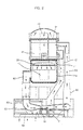
- FIG. 2 is a schematic cross-sectional view illustrating a construction of a passage system of a vacuum cleaner in accordance with an embodiment of the present invention.
- the passage system of a vacuum cleaner comprises a suction motor 10, a suction fan 20, a dust filter 31, a dust collecting bucket 41, a fan suction passage 42, a motor case 11, a plurality of discharging holes 11a, an ejector suction passage 62, an ejector 60, an ejector nozzle 61, an ejector chamber 63, a second suction nozzle 64 and a second suction passage 65.
- the suction motor 10 is installed adjacent to an upper end of the vacuum cleaner to provide the suction force for draw the outside air into the vacuum cleaner.
- the suction fan 20 is located on an upper end of the suction motor 10 and has blades which receive the suction force from the suction motor 10 and thereby suck the outside air.
- the dust filter 31 is arranged above the suction fan 20 to filter out dust and other particles contained in the outside air drawn in by the suction fan 20.
- the dust filter 31 has a doughnut-shaped configuration.
- the dust-collecting bucket 41 is positioned below the dust filter 31 to collect dust and other particles filtered by the dust filter 31.
- the dust collecting bucket 41 has a hollow configuration.
- the fan suction passage 42 is placed at the center portion of the dust collecting bucket 41 in a manner such that outside air that has been through the filtering process to remove the dust and the like by the dust filter 31, flaws through the fan suction passage 42 toward the suction fan 20.
- the fan suction passage 42 has a cylindrical shaped which is opened at an upper end thereof.
- the motor case 11 is formed to have a cylindrical shape to accommodate the suction motor 10.
- the plurality of discharging holes 11a are formed on a circumferential outer surface of the motor case 11 at predetermined places in a manner to exhaust the air that has been pressurized while passing through the suction fan 20 to the outside.
- the ejector suction passage 62 serves as an exhausting passage and is connected at one end thereof to the circumferential outer surface of the motor case 11 at a predetermined place in a manner such that the air which has been passed through the suction fan 20, can be reutilized.
- the ejector 60 is formed at the other end of the ejector suction passage 62 to exhaust the air which passed through the ejector suction passage 62.
- the ejector nozzle 61 is placed at the lower end of the ejector 60 to further pressurize the air which has been already pressurized while passing through the suction fan 20, and then exhaust the air at a high velocity.
- the ejector chamber 63 is defined in a manner such that an inside of the ejector chamber 63 remains under a low pressure by the air which is ejected from the ejector nozzle 61 at a high speed.
- the second suction nozzle 64 is formed at a lower end of the ejector chamber 63 in a manner such that outside air can be sucked therein.
- the second suction passage 65 is connected at one end thereof to the duct collecting bucket 41 in a manner such that air which is ejected therein from the ejector nozzle 61 and sucked therein from the ejector chamber 63, is guided toward the suction fan 20.
- a second suction path operates in the same manner as a suction path of the conventional vacuum cleaner.
- the second suction path according to the present invention is formed with a first suction nozzle 71 and a first suction passage 72.
- the first nozzle 71 directly receives the suction force generated by the suction motor 10 to draw in the outside air containing dust and other particles with intensive force.
- One end of the first suction passage 72 is connected to the dust-collecting bucket 41 and the other end is connected to the first suction nozzle 71, so that the outside air, which is drawn into the vacuum cleaner by the first suction nozzle 71, can pass through the first suction passage 72.
- first suction nozzle 71 and the second suction nozzle 64 are formed at the lowermost end of the entire vacuum cleaner structure to allow dust and the like existing on a floor to be easily drawn in along with outside air.
- the suction motor 10 rotates, and at the same time, the suction fan 20 which is connected to the suction motor 10 also rotates.
- the suction fan 20 If the suction fan 20 is rotated, the outside air is drawn in and passes through the first suction nozzle 71, the first suction passage 72, the dust collecting bucket 41, the dust filter 31 and the fan suction passage 42 in order. Upon reaching the suction fan 20 and the suction motor 10 after passing through the fan suction passage 42, air cools the suction motor 10 and at the same time is pressurized by the suction motor 10.
- the motor case 11 which accommodates the suction motor 10, is attached with the plurality of discharging holes 11a in which predetermined amount of air that has been pressurized while passing through the suction fan 20, is discharged to the outside, and the remaining predetermined amount of the air which has been pressurized while passing through the suction fan 20 flows into the ejector 60 through the ejector suction passage 62.
- a ratio between the preselected amount which is discharged to the outside through the plurality of discharging holes 11a and the predetermined amount which flows out through the ejector suction passage 62, can be adjusted according to the needs by adjusting the size and the number of the discharging holes 11a.
- the air which flows into the ejector 60, is exhausted through the ejector nozzle 61 formed at the free end of the ejector 60. Since the air is exhausted under a high pressure, it is to be readily understood that the surrounding area near the ejector nozzle 61 is maintained under a remarkably low pressure as explained in the Bernoulli's theorem, and the inside of the ejector chamber 63 which includes the discharging end of the ejector 60, also remains in a significantly low pressure.
- the outside air is drawn into the vacuum cleaner through the second suction nozzle 64 which is formed at a predetermined position in the ejector chamber 63, as in the case of the first suction nozzle 71.
- the Bernoulli's theorem applies to all incompressible fluid.
- water heads are divided into a pressure head (P/ ⁇ ) due to a pressure of fluid, a velocity head (V 2 /2g) due to a flow velocity of the fluid, and a position head (Z) due to a height of the fluid.
- the Bernoulli's theorem shows that the total sum of the three heads is always held equal at any point in the fluid.
- the second suction nozzle 64 is placed below the ejector chamber 63 to intake the outside air which then gets mixed up with the air exhausted from the ejector nozzle 61 before passing through the second suction passage 65. Consequently, in the passage system of a vacuum cleaner according to the present invention includes two suction nozzles that are formed at the outside air suction paths through which dust and the like can be sucked into the vacuum cleaner. Particularly, since the predetermined amount of air that has passed through the suction motor 10 is utilized to draw in the outside air, an efficiency of the vacuum cleaner is increased.
- FIG. 3 is a schematic cross-sectional view illustrating a construction of a passage system of a vacuum cleaner in accordance with another embodiment of the present invention.
- this passage construction makes not only the passage system of a vacuum cleaner more complex but also a manufacturing procedure thereof complicated.
- an outside air passage 70 in which the first suction passage 72 and the second suction passage 65 merge is independently formed.
- the passage system of a vacuum cleaner in accordance with the present invention allows the outside air containing dust and other particles to flow into the dust-collecting bucket 41 via the outside air passage 70.
- the passage system of a vacuum cleaner according to the present invention provides more powerful suction force for sucking the outside air through two sucking passages in the passage system, thus the cleaning process can be performed more quickly. Also, when compared with the conventional vacuum cleaner, less amount of input power is required for sucking the same amount of outside air thereby substantially saving energy. Moreover, in the case a rechargeable vacuum cleaner wherein the output of a motor cannot be raised beyond a predetermined level due to limitation within its own specification, greater cleaning capability can be accomplished when the passage system in accordance with the present invention is applied.
Landscapes
- Nozzles For Electric Vacuum Cleaners (AREA)
- Jet Pumps And Other Pumps (AREA)
Abstract
Description
Claims (9)
- A passage system of a vacuum cleaner, comprising:an ejector suction passage which is connected to one end of an outer surface of a motor case to reutilize air which has been exhausted from a suction motor;an ejector formed at the end of the ejector suction passage for accumulating air that has passed through the ejector suction passage;an ejector nozzle formed at one end of the ejector for exhausting the air at a high speed and under a low pressure;a second suction passage having one end placed at a predetermined distance from the ejector nozzle and the other end connected to a dust collecting bucket, such that the air discharged from the ejector nozzle and the air existing in an ejector chamber are simultaneously drawn in together into an ejector chamber and thereafter flows in the direction of a suction motor,an ejector chamber which is formed in the inside of the ejector nozzle, and one end of the second suction passage is connected in the ejector chamber so that an inside of the ejector chamber remains under a low pressure;a second suction nozzle formed at a predetermined position in the ejector chamber to draw in the outside air at a high speed;a first suction nozzle placed at a predetermined position of the vacuum cleaner to draw the air in at a high velocity by a suction force generated by the suction motor; anda first suction passage having one end which is fastened to the first suction nozzle and the other end is connected to a predetermined part of the dust collecting bucket, in a manner such that outside air which is drawn in via the first suction nozzle, is guided toward the suction motor.
- The passage system of claim 1, wherein the outer surface of the motor case is formed with a plurality of discharging holes in which a predetermined amount of air is exhausted to the outside.
- The passage system of claim 1, wherein a suction fan for drawing the air in is placed above the suction motor.
- The passage system of claim 1, wherein the dust collecting bucket is installed adjacent to a suction opening of the suction motor, and a fan suction passage is formed to allow the air that has been filtered passes through in the direction of the suction motor.
- The passage system of claim 4, wherein the fan suction passage is formed in a cylindrical shape.
- The passage system of claim 4, wherein a dust filter is installed between a suction inlet of the fan suction passage and the first and second suction passages in a manner such that the outside air which has been filtered can be flow through the fan suction passage toward the suction motor.
- The passage system of claim 1, further comprising:an outside air passage for merging the first suction passage and the second suction passage so that outside air containing dust and other particles becomes mixed with the air exhausted from the ejector nozzle before flowing into the dust collecting bucket.
- The passage system of claim 1, wherein the first suction nozzle is formed at a lowermost end of the vacuum cleaner.
- The passage system of claim 1, wherein the second suction nozzle is formed at a lowermost end of the vacuum cleaner.
Applications Claiming Priority (4)
| Application Number | Priority Date | Filing Date | Title |
|---|---|---|---|
| KR10-2000-0058080A KR100375625B1 (en) | 2000-10-04 | 2000-10-04 | The flow system of vacuum cleaner |
| KR2000058079 | 2000-10-04 | ||
| KR2000058080 | 2000-10-04 | ||
| KR10-2000-0058079A KR100375624B1 (en) | 2000-10-04 | 2000-10-04 | The flow system of vacuum cleaner |
Publications (3)
| Publication Number | Publication Date |
|---|---|
| EP1195124A2 true EP1195124A2 (en) | 2002-04-10 |
| EP1195124A3 EP1195124A3 (en) | 2005-12-28 |
| EP1195124B1 EP1195124B1 (en) | 2007-10-24 |
Family
ID=26638438
Family Applications (1)
| Application Number | Title | Priority Date | Filing Date |
|---|---|---|---|
| EP01402323A Expired - Lifetime EP1195124B1 (en) | 2000-10-04 | 2001-09-07 | Passage system of vacuum cleaner |
Country Status (4)
| Country | Link |
|---|---|
| US (1) | US6484355B2 (en) |
| EP (1) | EP1195124B1 (en) |
| JP (1) | JP3542788B2 (en) |
| DE (1) | DE60131055T2 (en) |
Families Citing this family (4)
| Publication number | Priority date | Publication date | Assignee | Title |
|---|---|---|---|---|
| KR100693835B1 (en) | 2005-07-26 | 2007-03-12 | (주)디케이엠엔이 | Vacuum suction device |
| AU2016285478A1 (en) * | 2015-06-30 | 2018-02-22 | Control Wizard Pty Ltd | A surface treatment appliance, a filter and components therefor |
| CN112620291A (en) * | 2020-12-24 | 2021-04-09 | 广东电网有限责任公司佛山供电局 | Dust collector of distribution equipment |
| CN114733289B (en) * | 2022-04-27 | 2024-05-14 | 芦山湘邻纺织有限公司 | Spinning machine |
Family Cites Families (10)
| Publication number | Priority date | Publication date | Assignee | Title |
|---|---|---|---|---|
| US2746078A (en) * | 1950-11-02 | 1956-05-22 | Syntron Co | Vacuum cleaner |
| US3206787A (en) * | 1963-01-28 | 1965-09-21 | Tennant Co G H | Scrubbing device |
| US3562846A (en) * | 1969-04-29 | 1971-02-16 | Marven Creamer | Apparatus for collecting surface liquids |
| US3704482A (en) * | 1970-10-08 | 1972-12-05 | Joseph W Brannon | Cleaning device |
| CA972510A (en) * | 1973-03-16 | 1975-08-12 | Henry Loetkeman | Hygienic vacuum cleaner with a circulating air flow |
| US4023233A (en) * | 1975-08-12 | 1977-05-17 | Warwick Pump And Engineering Company Limited | Surface cleaning device |
| DE3406603A1 (en) * | 1983-02-28 | 1984-09-06 | Gorenje Muta tovarna poljedelskega orodja, kmetijskih strojev in livarskih izdelkov n.sol.o. Muta, Muta | CLEANER |
| DE8513126U1 (en) * | 1985-05-04 | 1985-08-01 | Fasse, geb. Brink, Käthe, 2950 Leer | Circulating air vacuum cleaner |
| DE19530976A1 (en) * | 1995-08-23 | 1997-02-27 | Paul Recktenwald | Vacuum cleaner |
| US6725500B2 (en) * | 2001-05-03 | 2004-04-27 | Vortex, L.L.C. | Air recirculating surface cleaning device |
-
2001
- 2001-08-22 US US09/933,949 patent/US6484355B2/en not_active Expired - Fee Related
- 2001-08-24 JP JP2001253947A patent/JP3542788B2/en not_active Expired - Fee Related
- 2001-09-07 EP EP01402323A patent/EP1195124B1/en not_active Expired - Lifetime
- 2001-09-07 DE DE60131055T patent/DE60131055T2/en not_active Expired - Lifetime
Also Published As
| Publication number | Publication date |
|---|---|
| JP2002119446A (en) | 2002-04-23 |
| DE60131055T2 (en) | 2008-08-07 |
| JP3542788B2 (en) | 2004-07-14 |
| EP1195124B1 (en) | 2007-10-24 |
| US20020038491A1 (en) | 2002-04-04 |
| DE60131055D1 (en) | 2007-12-06 |
| US6484355B2 (en) | 2002-11-26 |
| EP1195124A3 (en) | 2005-12-28 |
Similar Documents
| Publication | Publication Date | Title |
|---|---|---|
| US7550021B2 (en) | Portable cyclonic dust collection system | |
| CA1182613A (en) | Vacuum cleaning appliance having a plurality of cyclone separators of different efficiencies | |
| US7996957B2 (en) | Centrifugal dirt separation configurations for household-type and shop-type vacuum cleaners | |
| EP3372137B1 (en) | Three-tier cyclone dust bin filtration system and vacuum cleaner comprising the system | |
| JP3729354B2 (en) | Dust collector | |
| WO2020108492A1 (en) | Handheld cleaning apparatus | |
| JP3659191B2 (en) | Centrifugal dust collector and electric vacuum cleaner using the same | |
| CN110840326B (en) | Dust collection device and dust collection equipment | |
| KR20080019232A (en) | Cyclonic separator | |
| JP2002526233A (en) | Particle capture and collection device | |
| CA2450335A1 (en) | Upright type vacuum cleaner | |
| JPH08322768A (en) | Electric vacuum cleaner | |
| JP2003310502A (en) | Electric vacuum cleaner | |
| CN211484334U (en) | Dust suction device and dust suction equipment | |
| US6615447B2 (en) | Vacuum cleaner | |
| US6484355B2 (en) | Passage system of vacuum cleaner | |
| CN108294687A (en) | Whirlwind with storage ash content from filtration system, hand held cleaner and stick vacuums | |
| CN214682318U (en) | Cyclone separator capable of preventing dust exhaust pipe from being blocked | |
| KR100405980B1 (en) | The flow system of vacuum cleaner with ejector | |
| CN108125619A (en) | A kind of dust and gas separator and the dust catcher using the device | |
| JPH07275164A (en) | Upright vacuum cleaner | |
| CN218165134U (en) | Dust-gas separating device | |
| CN115120134B (en) | Cyclone separators and surface cleaning devices | |
| CN223614750U (en) | Cleaning apparatus | |
| CN220817787U (en) | Portable negative pressure draws dust collector for power plant |
Legal Events
| Date | Code | Title | Description |
|---|---|---|---|
| PUAI | Public reference made under article 153(3) epc to a published international application that has entered the european phase |
Free format text: ORIGINAL CODE: 0009012 |
|
| 17P | Request for examination filed |
Effective date: 20010913 |
|
| AK | Designated contracting states |
Kind code of ref document: A2 Designated state(s): AT BE CH CY DE DK ES FI FR GB GR IE IT LI LU MC NL PT SE TR |
|
| AX | Request for extension of the european patent |
Free format text: AL;LT;LV;MK;RO;SI |
|
| PUAL | Search report despatched |
Free format text: ORIGINAL CODE: 0009013 |
|
| AK | Designated contracting states |
Kind code of ref document: A3 Designated state(s): AT BE CH CY DE DK ES FI FR GB GR IE IT LI LU MC NL PT SE TR |
|
| AX | Request for extension of the european patent |
Extension state: AL LT LV MK RO SI |
|
| AKX | Designation fees paid |
Designated state(s): DE FR GB IT |
|
| 17Q | First examination report despatched |
Effective date: 20061010 |
|
| GRAP | Despatch of communication of intention to grant a patent |
Free format text: ORIGINAL CODE: EPIDOSNIGR1 |
|
| GRAS | Grant fee paid |
Free format text: ORIGINAL CODE: EPIDOSNIGR3 |
|
| GRAA | (expected) grant |
Free format text: ORIGINAL CODE: 0009210 |
|
| AK | Designated contracting states |
Kind code of ref document: B1 Designated state(s): DE FR GB IT |
|
| REG | Reference to a national code |
Ref country code: GB Ref legal event code: FG4D |
|
| REF | Corresponds to: |
Ref document number: 60131055 Country of ref document: DE Date of ref document: 20071206 Kind code of ref document: P |
|
| ET | Fr: translation filed | ||
| PLBE | No opposition filed within time limit |
Free format text: ORIGINAL CODE: 0009261 |
|
| STAA | Information on the status of an ep patent application or granted ep patent |
Free format text: STATUS: NO OPPOSITION FILED WITHIN TIME LIMIT |
|
| 26N | No opposition filed |
Effective date: 20080725 |
|
| PGFP | Annual fee paid to national office [announced via postgrant information from national office to epo] |
Ref country code: GB Payment date: 20090902 Year of fee payment: 9 |
|
| PGFP | Annual fee paid to national office [announced via postgrant information from national office to epo] |
Ref country code: DE Payment date: 20090903 Year of fee payment: 9 |
|
| PGFP | Annual fee paid to national office [announced via postgrant information from national office to epo] |
Ref country code: FR Payment date: 20091012 Year of fee payment: 9 Ref country code: IT Payment date: 20090916 Year of fee payment: 9 |
|
| GBPC | Gb: european patent ceased through non-payment of renewal fee |
Effective date: 20100907 |
|
| PG25 | Lapsed in a contracting state [announced via postgrant information from national office to epo] |
Ref country code: IT Free format text: LAPSE BECAUSE OF NON-PAYMENT OF DUE FEES Effective date: 20100907 |
|
| REG | Reference to a national code |
Ref country code: FR Ref legal event code: ST Effective date: 20110531 |
|
| REG | Reference to a national code |
Ref country code: DE Ref legal event code: R119 Ref document number: 60131055 Country of ref document: DE Effective date: 20110401 |
|
| PG25 | Lapsed in a contracting state [announced via postgrant information from national office to epo] |
Ref country code: FR Free format text: LAPSE BECAUSE OF NON-PAYMENT OF DUE FEES Effective date: 20100930 Ref country code: DE Free format text: LAPSE BECAUSE OF NON-PAYMENT OF DUE FEES Effective date: 20110401 |
|
| PG25 | Lapsed in a contracting state [announced via postgrant information from national office to epo] |
Ref country code: GB Free format text: LAPSE BECAUSE OF NON-PAYMENT OF DUE FEES Effective date: 20100907 |