TECHNICAL FIELD
The present invention relates to a reclining apparatus suitable for
adjusting an angle of incline of a backrest, for example, in a seat for an
automobile.
BACKGROUND ART
Various types exist in the reclining apparatus, for example, there has
been suggested an internal gear type reclining apparatus as described in
Japanese Patent Application Laid-Open No. 7-231820. The internal gear
type reclining apparatus is, as one embodiment thereof is shown in Fig. 18,
provided with a fixed plate 3 having a pair of guide convex portions 1 and 2
opposing to each other, a slide gear 4 received between the guide convex
portions 1 and 2, a rotary plate 6 having an internal gear 5, a cam member 7
and the like. The cam member 7 can be rotated in a direction of an arrow A
in Fig. 18 (a lock canceling direction) by an operating lever 8. The fixed
plate 3 is fixed to a frame in a seat cushion side. The rotary plate 6 is fixed
to a frame in a seat back side and can rotate around a shaft 9 integrally
together with the seat back.
A gear teeth portion 10 freely engaged with and disengaged from the
internal gear 5 is formed in a front end portion of the slide gear 4. When
the slide gear 4 is pressed toward the internal gear 5 by a cam surface 11 of
the cam member 7, the gear teeth portion 10 is engaged with the internal
gear 5 so as to be in a lock condition, whereby the rotary plate 6. That is,
the seat back is fixed at a desired angle.
An engaging portion 13 engaging with a receiving portion 12 of the
slide gear 4 is formed in the cam member 7. When the operating lever 8 is
rotated in a clockwise direction and the slide gear 4 is driven in a direction
moving apart from the internal gear 5 by the engaging portion 13, an
engagement between the slide gear 4 and the internal gear 5 is canceled and
the lock thereof is canceled, so that the rotary plate 6. That is, the seat back
can rotate around the shaft 9.
In the reclining apparatus (Fig. 18) mentioned above, at a time of
adjusting an angle of incline of the seat back in a condition that a passenger
sits on the seat, a load (a backward load) of an upper half of the sitting
person is applied to the seat back. In this case, since the front end portion
of the slide gear 4 is going to rotate in a direction shown by an arrow R1
integrally together with the rotary plate 6 in a condition that the slide gear 4
is engaged with the internal gear 5 as shown in Fig. 19, a clockwise moment
M1 is applied to the slide gear 4. The slide gear 4 is tilted due to the
moment M1, and the slide gear 4 becomes in a condition of being pressed to
a contact point B near a corner in a base end side of one guide convex
portion 1 and a contact point C near a corner in front end side of another
guide convex portion 2.
In this condition, when the engaging portion 13 of the cam member
7 is rotated in a clockwise direction by rotating the operating lever 8 in a
lock canceling direction as shown in Fig. 20, a force f1 in a direction moving
the slide gear 4 apart from the internal gear 5 is applied to the receiving
portion 12 of the slide gear 4. However, since the force f1 generates a
moment further tilting the slide gear 4 in a clockwise direction, the contact
pressure in the contact points B and C is further increased, so that a great
lock canceling force is required for operating the operating lever 8.
Accordingly, the sitting person operates the operating lever 8 so as not to
apply so much load to the seat back, and it is difficult to operate.
In the case of assuming a rear-end collision, or the like, in the lock
condition in Fig. 18, a great input is applied in a direction shown by an arrow
R1 in Fig. 19, whereby the moment M1 applied to the slide gear 4 is further
increased. Accordingly, the contact force in the contact points B and C is
further increased. Accordingly, in an engaging portion 15 close to the front
end of the guide convex portion 2, a gap G between the gear teeth portion 10
and the internal gear 5 tends to be increased as shown in Fig. 21. As a
result, the engaging efficiency between the slide gear 4 and the internal gear
5 is reduced, and it is difficult to ensure the engaging strength and the
engaging rigidity. Accordingly, it is necessary to employ countermeasures
such as increasing the gear teeth thickness or increasing the number of gear
teeth. However, there is a limit for increasing the thickness of the gear
teeth and the number of the gear teeth, and it causes increase of the whole
size of the reclining apparatus.
Furthermore, in a reclining apparatus described in Japanese Patent
Application Laid-Open No. 8-52040, a flange of a bracket formed in a shape
obtained by vertically notching a hat is fixed to a fixed plate, an inner
peripheral side end portion of a spiral spring is engaged with a notched
cylindrical portion of the bracket, and an outer peripheral side end portion
thereof is engaged with a pin fixed to a rotary plate. In this case, the
bracket is positioned by fitting two holes formed in the flange to a convex
portion formed in the fixed plate, and is fixed to the fixed plate by welding
the flange to the fixed plate. Furthermore, the pin is fixed to the rotary
plate by being inserted into a through hole formed in the rotary plate and
thereafter caulking an inserted end.
Furthermore, in the reclining apparatus, the following structure is
employed so that the fixed plate and the rotary plate slide with each other in
a circumferential direction. That is, a circular recess step portion is formed
in a center portion of one plate and a convex step portion fitting into the
recess step portion is formed in a center portion of another plate, whereby
both elements can relatively rotate around an axis. Furthermore, a plurality
of pins having flanges are caulked and fixed to one plate, and the flanges of
the pins prevent the outer peripheral portion of the end surface of another
plate from moving in an axial direction. Accordingly, both plates relatively
rotate in a circumferential direction in a condition of being in contact with
each other.
Furthermore, it is necessary to provide a limit in a tilt range of the
seat back. For example, in Japanese Patent Application Laid-Open No. 11-56510,
there is disclosed an arrangement structured such that by forming an
elongated through hole formed in a circular arc shape in one plate and fixing
a pin inserted into the elongated through hole to another plate, the pin is
brought into contact with the end portion of the elongated through hole and a
seat back does not tilt more than the contact portion.
In the arrangement disclosed in Japanese Patent Application Laid-Open
No. 8-52040, since the bracket engaged with the inner peripheral side
end portion of the spiral spring is substantially formed in a hat, a space
occupied by the flange of the bracket is increased, and there is a problem that
the size of the bracket is increased. Furthermore, since the bracket is fixed
by welding the edge portion of the flange to the fixed plate, the distance
between the welded portion of the bracket and the cylindrical portion to
which the load due to the spiral spring is applied is increased. Accordingly,
in order to prevent a deformation between the welded portion and the
cylindrical portion, it is necessary to increase a thickness of the bracket, so
that there is a problem that not only the weight of the reclining apparatus is
increased but also the1 material cost and the working cost are increased.
Furthermore, a restricting means for the rotary plate using the
elongated through hole and the pin inserted thereto is employed in many
reclining apparatuses in addition to the structure disclosed in Japanese Patent
Application Laid-Open No. 11-56510. However, since a pin exclusive for
restricting a rotation is required, there is a problem that a number of the parts
is increased.
Furthermore, as described in Japanese Patent Application Laid-Open
No. 8-52040, in the arrangement for preventing another plate from relatively
moving in the axial direction by the pin having the flange, at least three pins
are required in view of a structural stability. However, there is a
requirement to make the number of the parts as small as possible.
Furthermore, as described in Japanese Patent Application Laid-Open
No. 8-52040, in the arrangement in which the convex step portion is fitted
into the recess step portion so as to slide the fixed plate and the rotary plate
in the circumferential direction, a contact area of the both is great, and a
frictional resistance is increased due to burrs formed at a time of press
punching, so that there may be a problem in which the seat back does not
smoothly tilt. On the contrary, when a gap is formed between the fixed
plate and the rotary plate, dusts enter into the sliding portion and a resistance
in rotation is increased.
In general, the reclining apparatus is exerted with a load which is
input via the seat back from a back portion of the sitting person, and the back
frame carries the load within the seat back. A mounting portion of the
reclining apparatus is mounted to the back frame by means of welding or
bolts, and is directly supported to an upper rail of the seat slide or indirectly
supported via a cushion frame. The load of the sitting person applied to the
back frame is naturally applied to the reclining apparatus. However, the
load is mainly applied to an engaging portion between the rotary plate and
the fixed plate, that is, the engaging portion between the gear teeth portion of
the slide gear and the internal gear.
In this case, a relational formula of the load in the reclining apparatus
as mentioned above is shown as follows.
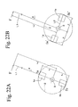
As shown in Fig. 22A, on the assumption that the load applied to the
seat back is defined as "F", the distance from the center of rotation of the
seat back to the point of application is defined as "L", the radius of the pitch
circle between the slide gears 1a and 1b and the gear teeth portion of the
internal gear 2 is defined as "r", the reaction force generated due to the
engagement between the upper slide gear 1a and the internal gear 2 is
defined as "fa", and the reaction force generated due to the engagement
between the lower slide gear 1b and the internal gear 2 is defined as "fb", the
following formula is obtained on the basis of balance of force.
F + fb = fa
The following formula is obtained on the basis of balance of moment.
F X L = (fa + fb) X r
The following formulas are obtained on the basis of two formulas mentioned
above.
fa=(L+r)XF/2r
fb = (L-r)XF/2r
Accordingly, the load applied to the engaging position between the
slide gears 1a and 1b and the internal gear 2 is different between upper and
lower portions, and it is known that the load applied to the upper slide gear
1a is larger than the load applied to the lower slide gear 1b. Accordingly,
the strength of the upper slide gear 1a must be higher than the strength of the
lower slide gear 1b. This matter can be applied to the guide portion of the
slide gears 1a and 1b. However, in an actual condition, two kinds of slide
gears having different strength designs are not manufactured in order to
simplify manufacturing operations or assembling operations. Furthermore,
when the parts of the slide gears are made common as mentioned above, the
strength design is made so as to cope with the upper load condition having a
great load. This results in unnecessary increase of the thickness or the size
in the slide gear arranged in the lower side, and results in increase of the size
or the weight in overall the apparatus.
Furthermore, generally, in a condition in which the slide gear and the
internal gear are engaged with each other, a back-lash is inevitably formed
by the clearance for the engagement between the both gears. The back-lash
is instantaneously formed when the sitting person leans against the seat back,
however, if there is a difference in the load applied to the slide gear as
mentioned above, there is a case in which the back-lash is formed two times
at every engaging positions. Figs. 23A ad 24A are graphs showing a
condition in which the back-lash is formed. Fig. 23A shows a condition in
which a load is applied to the seat back, whereby at first a back-lash is
formed at the upper engaging position to which a great load is applied (a
portion shown by reference symbol g1), and next back-lash (a portion shown
by reference symbol g2) according to a small load application is formed at
the lower engaging position. Fig. 24A simply shows a displacement of the
seat back with respect to the case in which a load is applied to the seat back,
and a parallel portion shown by reference symbols g1 and g2 shows a
formation of the back-lash. As mentioned above, when the back-lash is
formed in two stages, the sitting person feels discomfort and unpleasant
sensation although these senses may be instantaneous, so that this is a
problem to be improved.
In the reclining apparatus mentioned above, there is provided with a
holding member for guiding rotation of the rotary plate and preventing both
of the plates from breaking away from each other. The holding member
has a pin and a flange fixed to the front end portion of the pin. For example,
in the reclining apparatus disclosed in Japanese Patent Application Laid-Open
Nos. 7-136032 and 7-231820, the holding member is provided in both
plates one by one, and is arranged so as to slidably hold an outer peripheral
portion of an opposing plate between its own plate and the flange.
In the reclining apparatus mentioned above, when the sitting person
leans against the seat back and the load is applied to the seat back, the load is
transmitted to the engaging position between the slide gear and the internal
gear via the rotary plate. Therefore, a force breaking away both of the plate
from each other is generated between the fixed plate and the rotary plate
around the engaging position. Actually, it is possible to prevent the plates
from breaking away by the holding member. However, there is a problem
in which since the holding member provided in the rotary plate side naturally
moves together with the rotary plate, the relative position between the
holding member and the engaging position changes according to the angle of
tilt of the seat back, and the elements sometimes move greatly apart from
each other. That is, the holding member in the rotary plate side largely
moves away from the engaging position at which the force breaking both of
the plates away from each other is generated. Accordingly, the holding
force applied by the holding member is not effectively applied to the
engaging position, so that the engaging force is reduced. Therefore, the
sizes of the holding member, the slide gear and the like are increased so as to
ensure the strength thereof, and overall the apparatus has disadvantages in
which the size and the weight thereof increase.
A first object of the present invention is to provide a reclining
apparatus which can increase an engaging strength between an internal gear
and a slide gear in the case of assuming a rear-end collision or the like.
A second object of the present invention is to provide a reclining
apparatus which requires a small operating force at a time of canceling a
lock and has an improved operability.
A third object of the present invention is to reduce material cost and
working cost as well as making a bracket engaged with an inner peripheral
side end portion of a spiral spring compact and thin so as to achieve weight
saving.
A fourth object of the present invention is to achieve restriction of
rotation of a rotary plate and restriction of movement in an axial direction
against a fixed plate by reduced number of parts.
A fifth object of the present invention is to ensure tight contact
between the fixed plate and the rotary plate so as to reduce frictional
resistance between the both while preventing dusts from entering.
A sixth object of the present invention is to achieve compact design
and weight saving, and improvement of strength while it is a matter of
course to commonly use parts in a slide gear. A seventh object of the
present invention is to reduce a back-lash generated at an engaging position
between a slide gear and an internal gear.
An eighth object of the present invention is to provide a reclining
apparatus which can effectively restrict a force applied so that a rotary plate
tends to break away from a fixed plate without relation to a position of the
rotary plate, as a result, can increase an engaging force between the slide
gear and the internal gear so as to achieve compact design and weight saving,
and improvement of strength.
DISCLOSURE OF THE INVENTION
The reclining apparatus in accordance with the present invention is
applied to a reclining apparatus comprising: a fixed plate in which a first
guide portion having a pair of mutually opposing guide walls and a second
guide portion having a pair of mutually opposing guide walls are formed;
a shaft provided in the fixed plate so as to freely rotate around an axis in a
horizontal direction; a rotary plate relatively rotating around the shaft with
respect to the fixed plate and in which an internal gear is formed along a
circular arc around the shaft; a first slide gear received between respective
guide walls of the first guide portion and freely moving between a lock
position engaged with the internal gear and a lock canceling position moving
apart from the internal gear; a second slide gear received between respective
guide walls of the second guide portion and freely moving between a lock
position engaged with the internal gear and a lock canceling position moving
apart from the internal gear; and a cam member provided between the first
slide gear and the second slide gear and simultaneously driving the slide
gears between the lock position and the lock canceling position.
Furthermore, the invention achieving the first object is arranged such
that a supporting portion having an inclined surface preventing the slide gear
from moving in a direction of a rotational moment applied to the slide gear
due to a backward load applied to the seat back is provided in a portion in
which the cam member and the slide gear oppose to each other. In
accordance with the invention, when a great backward load is input to the
seat back such as the case of assuming a rear-end collision or the like, it is
possible to prevent the slide gear from moving in a direction of the rotational
moment, by the supporting portion.
In accordance with the invention for achieving the second object, the
cam member has a pair of hook portions engaging with receiving portions
respectively formed in the first and second slide gears, the hook portion and
the receiving portion have a cam surface pressing the slide gear to the
internal gear in a condition that the cam member rotates in the direction of
the lock position, and the hook portion and the receiving portion are formed
in a shape displacing the slide gear in an opposite direction to the rotational
moment applied to the slide gear due to the backward load applied to the seat
back (a direction canceling the rotational moment) when the cam member
rotates in the lock canceling direction. In accordance with the invention,
when the cam member is rotated in the lock canceling direction, the gear
teeth portion of the slide gear moves in the direction moving apart from the
internal gear while the slide gear displaces in a direction that an incline of the
slide gear with respect to the guide wall becomes small, so that a contact
pressure of the slide gear with respect to the guide wall is reduced and the
lock canceling force can be reduced.
In this invention, it is preferable that the hook portion and the
receiving portion are respectively provided near a center line of the slide
gear in an area inside both side surfaces of the slide gear. By making the
structure in the manner mentioned above, it is possible to construct the slide
gear compact.
The invention for achieving the third object is arranged such that the
bracket is provided with a vertical plate portion protruding out from an end
surface of the fixed plate in an axial direction so as to engage with an inner
peripheral side end portion of the spiral spring, and a bottom plate portion
extending toward the shaft from an edge portion in the fixed plate side of the
vertical plate portion, the bracket is fixed to the fixed plate by the bottom
plate portion, the vertical plate portion is formed in a substantially
semicircular cylindrical shape around the shaft, a plurality of notches
extending to the vertical plate portion and the bottom plate portion are
formed in a crossing portion between the vertical plate portion and the
bottom plate portion, and convex portions fitting to the notches are provided
in the fixed plate.
In accordance with the reclining apparatus having the structure
mentioned above, since the bottom plate portion of the bracket extends
toward the shaft from the edge portion of the vertical plate portion, there is
no flange protruding outward such as the bracket formed in a hat-shape, and
the load applied by the spiral spring engaging with the vertical plate portion
is supported by the convex portion located immediately below the vertical
plate portion. Accordingly, it is possible to make the bracket small, it is
possible to set the design strength of the vertical plate portion to be small,
and it is possible to make the thickness of the bracket thin. Furthermore,
since the load of the spiral spring is supported by the convex portion, in the
case of fixing the bracket to the fixed plate, for example, by means of
welding, it is sufficient to perform a welding such a degree that the bracket is
not broken away from the fixed plate. Accordingly, it is possible to
simplify the welding of the bracket to the fixed plate, and it is possible to
simply control a quality thereof. In this case, at a time of welding the
bracket to the fixed plate, it is simple to weld the convex portion of the fixed
plate to the notch of the bracket.
The invention for achieving the fourth object is arranged such that a
pin protruding to the fixed plate side along an axial direction is provided in
an outer peripheral portion of the rotary plate, an outer peripheral side end
portion of the spiral spring is engaged with the pin, and a flange preventing
the fixed plate from breaking away from the rotary plate is provided at a
middle position between the spiral spring and the fixed plate in the pin. In
accordance with the structure mentioned above, the pin serves two functions
comprising: (1) mounting the spiral spring, and (2) preventing the fixed plate
and the rotary plate from breaking away from each other. Furthermore,
since a stopper being brought into contact with the pin when the fixed plate
and the rotary plate relatively rotate to a predetermined range is provided in
the outer peripheral portion of the fixed plate, it is possible to give to the pin
third function (3) restricting the rotational range of the rotary plate, so that it
is possible to further reduce the number of the parts.
The stopper can be set as a limit at a time of backward tilting or
forward tilting the seat back, and it is possible to provide the limits at a time
of forward tilting and backward tilting by providing the stoppers at two
positions. In this case, in addition to the stopper with which the pin is
brought into contact, a plurality of flange portions protruding to an outer
peripheral side are formed in the fixed plate, and bolt holes for mounting the
reclining apparatus to the flame of the seat cushion are formed in the flange
portions. Accordingly, even when the stopper brought into contact with the
pin is further provided, it is possible to manufacture within a range of an
original yield.
The invention for achieving the fifth object is arranged such that in
one of the fixed plate and the rotary plate, a linear protrusion being in
slidable contact with another is provided all around the periphery of the shaft.
It is possible to reduce a frictional resistance while closely attaching the both
elements by sliding the fixed plate and the rotary plate with each other by the
narrow linear protrusion. The linear protrusion can be processed in
accordance with a press molding at a time of sheet metal processing the
fixed plate or the rotary plate. Since the internal gear of the rotary plate is
processed in accordance with the press molding, it is desirable to form the
linear protrusion in the fixed plate taking an influence given to the
processing into consideration.
The invention for achieving the sixth and seventh objects is arranged
such that an urging member interposed between the fixed plate and the rotary
plate and rotating the rotary plate in a direction in which the seat back tilts
forward is provided, and a center of an engaging position between the first
and second slide gears and the internal gear is arranged on a line vertically
crossing a line along a standard tilt angle of the seat back and passing
through a center of rotation of the rotary plate.
Fig. 22B schematically shows an arrangement of the slide gear in the
reclining apparatus in accordance with the present invention. As shown in
the drawing, a pair of slide gears 1a and 1b are arranged longitudinally, and a
center of the engaging position between the gear teeth portions of the slide
gears 1a and 1b and the internal gear 2, that is, a center of the load
application vertically crosses a line L1 extending along a standard tilt angle
of the seat back, and is positioned on a line L2 passing through a center
(an axis 3) of rotation of the rotary plate.
In this case, a relational formula of the load in the reclining apparatus
in accordance with the present invention is shown as follows.
As shown in Fig. 22B, on the assumption that a load applied to the
seat back is set to F, a distance from a center of rotation of the seat back to a
point of application is set to L, a radius of a pitch circle between the slide
gears 1a and 1b and the gear teeth portion of the internal gear 2 is set to r, a
reaction force generated due to an engagement between the front slide gear
1a and the internal gear 2 is set to fa, and a reaction force generated due to an
engagement between the rear slide gear 1b and the internal gear 2 is set to fb,
the following formulas are obtained on the basis of a balance of moment.
F x L = (fa' + fb') x r
fa' = fb'
The following formula is obtained on the basis of two formulas mentioned
above.
fa' = fb' = L x F/2r
Accordingly, a load applied to the engaging position of the slide gear
is the same between the front and rear portions. Therefore, it is possible to
design a pair of slide gears and the parts relating to the respective guide
portions and the like of the slide gears under the same load condition, and it
is possible to commonly use the parts. Furthermore, comparing the
formula (2) mentioned above with the formula (1), it is apparent that the load
fa' (= fb') applied to the engaging position of the present invention is smaller
than the load fa applied to the conventional upper engaging position.
Accordingly, it is possible to make the structure compact and light, and it is
possible to improve the strength. Furthermore, since the load applied to a
pair of slide gears is uniform, the backlashes generated at the engaging
positions of the slide gears are simultaneously generate, so that the
generating number of the backlash is reduced to one time.
Furthermore, since the load applied to a pair of slide gears is uniform,
the backlashes generated at the engaging positions of the slide gears are
simultaneously generated, so that it is possible to restrict the generation of
the backlash to one time. Figs. 23B ad 24B are graphs showing a condition
that the back-lash is generated in accordance with the present invention.
Fig. 23B shows a displacement of an upper end portion of the seat back
generated at a time of backward applying the load to the seat back and next
forward applying the load, and the backlash is generated at a portion shown
by reference symbol g1. Fig. 24B simply shows a displacement of the seat
back with respect to the case that the load is applied to the seat back, and a
parallel portion shown by reference symbol g1 shows a generation of the
back-lash. The backlash is generated at only one time in the case that the
load is applied to the seat back. As a result, it is possible to restrict a sense
of discomfort and an unpleasant sensation applied to the sitting person due to
the generation of the backlash as much as possible.
The invention for achieving the eighth object is arranged such that
there is provided with a holding member provided in the fixed plate,
rotatably supporting the rotary plate and preventing the rotary plate from
breaking away from the fixed plate, and an urging member interposed
between the fixed plate and the rotary plate and rotating the rotary plate in a
direction in which the seat back tilts forward.
In the reclining apparatus mentioned above, the rotary plate can be
rotated with respect to the fixed plate by rotating the shaft and moving the
first and second slide gears apart from the internal gear. The seat back is
fixed by tilting the seat back due to an elastic force of the spiral spring or
against the elastic force in this condition and reverse rotating the shaft at a
desired position so as to engage the respective slide gears with the internal
gear.
Furthermore, the present invention is characterized in that in the
structure mentioned above, the holding member provided in the fixed plate is
provided close to each of the slide gears and at least one by one in each of
the slide gears, and at least a part of the portion holding the rotary plate of
the holding member is located within a range of a width extending in an
engaging direction of the slide gear.
In accordance with the arranging aspect of the holding member as
mentioned above, the holding member always holds the rotary plate in the
fixed plate near the engaging position between the slide gear and the internal
gear without relation to the position (angle of rotation) of the rotary plate
rotating together with the tilt of the seat back. This is because the holding
member is provided in the fixed plate, and the relative position with respect
to the slide gear is always fixed without relation to the rotation of the rotary
plate. Since the holding member is located near the engaging position, it is
possible to effectively restrict a force breaking away both the plates and
generated around the engaging position. As a result, it is possible to always
sufficiently secure the engaging force between the slide gear and the internal
gear, and further it is possible to make the apparatus compact and light and
improve the strength. Particularly, in accordance with the present invention,
since at least a part of the portion holding the rotary plate in the holding
member is located within the range of the width extending in the engaging
direction of the slide gear, the operation restricting the force for breaking
away both the plates is more effectively applied.
BRIEF DESCRIPTION OF THE DRAWINGS
Fig. 1 is an exploded perspective view showing a left portion of a
reclining apparatus in accordance with a first embodiment of the present
invention;
Fig. 2 is an exploded perspective view showing a right portion of the
reclining apparatus in accordance with the first embodiment;
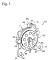
Fig. 3 is a perspective view of a condition of assembling the
reclining apparatus shown in Fig. 1;
Fig. 4 is a vertical cross sectional view of the reclining apparatus
shown in Fig. 1;
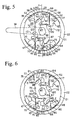
Fig. 5 is a side view of a part of the apparatus when the reclining
apparatus shown in Fig. 1 is in a locking condition;
Fig. 6 is a side view of a part of the apparatus when a backward load
is applied to the reclining apparatus shown in Fig. 1;
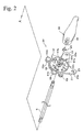
Fig. 7 is a side view when a cam member of the reclining apparatus
shown in Fig. 1 operates in a lock canceling direction;
Fig. 8 is a side view of a lock canceling condition of the reclining
apparatus shown in Fig. 1;
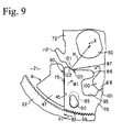
Fig. 9 is an enlarged view of a part of the reclining apparatus shown
in Fig. 1;
Fig. 10 is a cross sectional view showing a condition of cutting a
reclining apparatus in accordance with a second embodiment of the present
invention at a portion of an internal gear of a rotary plate;
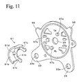
Fig. 11 is a perspective view showing a condition before fixing a
bracket to a part of the reclining apparatus shown in Fig. 1;
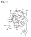
Fig. 12 is a perspective view showing a condition of fixing the
bracket after the condition shown in Fig. 11;
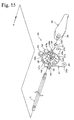
Fig. 13 is a side view showing a condition that a reclining apparatus
in accordance with a third embodiment of the present invention is attached to
a seat;
Fig. 14 is an exploded perspective view showing a left portion of a
reclining apparatus in accordance with a fourth embodiment of the present
invention;
Fig. 15 is an exploded perspective view showing a right portion of
the reclining apparatus in accordance with the fourth embodiment;
Fig. 16 is a cross sectional view showing a condition of cutting the
reclining apparatus in accordance with the fourth embodiment at a portion of
an internal gear of a rotary plate;
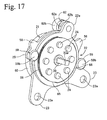
Fig. 17 is a perspective view of a condition of assembling the
reclining apparatus shown in Fig. 14;
Fig. 18 is a side view of a part of a conventional internal type
reclining apparatus;
Fig. 19 is a side view of a condition that a backward load is applied
to the reclining apparatus shown in Fig. 18;
Fig. 20 is a side view when a cam member of the reclining apparatus
shown in Fig. 18 is operated in a lock canceling direction;
Fig. 21 is an enlarged view of a part of an engaging portion between
a slide gear and an internal gear in Fig. 19;
Fig. 22A is a side view schematically showing an arrangement of a
slide gear in the conventional reclining apparatus;
Fig. 22B is a side view schematically showing an arrangement of a
slide gear in the reclining apparatus in accordance with the present invention;
Fig. 23A is a graph showing an amount of displacement of a seat
back at a time of applying forward and backward loads to the conventional
reclining apparatus;
Fig. 23B is a graph showing an amount of displacement of a seat
back at a time of applying forward and backward loads to the reclining
apparatus in accordance with the present invention;
Fig. 24A is a graph showing an amount of displacement of a seat
back at a time of applying a backward load to the conventional reclining
apparatus; and
Fig. 24B is a graph showing an amount of displacement of a seat
back at a time of applying a backward load to the reclining apparatus in
accordance with the present invention.
BEST MODE FOR CARRYING OUT THE INVENTION
FIRST EMBODIMENT
A description will be given below of a first embodiment in
accordance with the present invention with reference to Figs. 1 to 8.
Fig. 1 is an exploded perspective view showing a reclining apparatus
20 in a left side toward a forward moving direction in a seat for an
automobile, and Fig. 2 shows a right reclining apparatus 20'. These two
reclining apparatuses 20 and 20' are manufactured in a mirror image manner.
The reclining apparatus 20 shown in Fig. 1 is provided with a fixed plate 21
fixed to a frame of a cushion (a sitting portion) of a seat in the automobile or
the like, and a rotary plate 22 provided on the fixed plate 21. Both of the
fixed plate 21 and the rotary plate 22 correspond to a press molded product
made of a metal or a forged product in accordance with a cold forging or the
like.
A hole 23a inserting a bolt or the like for mounting to a frame in a
seat cushion side therethrough is formed in the fixed plate 21. A fixing
convex portion 24 protruded to an outer surface side in accordance with a
press molding is formed in the rotary plate 22, and is fixed to the seat back
by welding the fixing convex portion 24 to a frame 27 in the seat back side
as shown in Fig. 3.
Through holes 25 and 26 are formed in respective center portions of
the fixed plate 21 and the rotary plate 22. A shaft 30 is inserted to the
through holes 25 and 26 in a horizontal direction. The shaft 30 has a
flange-like end portion 31, a cam mounting portion 32 having a non-circular
cross section, a lever mounting portion 33 and the like. An operating lever
34 (shown in Fig. 4) for canceling the lock is mounted to the lever mounting
portion 33. The shaft 30 freely rotates around an axis O (shown in Figs. 1
and 3) thereof.
A first guide portion 41 and a second guide portion 42 punched out
so as to protrude to an inner side (a right side in Fig. 3) by the press molding
are provided in the fixed plate 21. The first guide portion 41 has convex
portions 47 and 48 including a pair of substantially parallel guide walls 45
and 46 opposing to each other. The second guide portion 42 has convex
portions 52 and 53 including a pair of substantially parallel guide walls 50
and 51 opposing to each other.
A pair of slits 55 recessed toward an outer side (a left side in Fig. 3)
by a press molding are provided between the first guide walls 45 and 46. A
pair of slits 56 recessed toward an outer side by a press molding are also
provided between the second guide walls 50 and 51. Furthermore, a pair of
positioning convex portions 57 punched out to an outer side by a press
molding are provided near the center through hole 25. The following
bracket 61 is fixed to the positioning convex portions 57.
The first convex portions 47 and 48 and the second convex portions
52 and 53 are both formed in a diverging shape such as a width is expanded
toward an outer peripheral side of the fixed plate 21. By forming the
convex portions 47, 48, 52 and 53 in the diverging shape mentioned above, it
is possible to widely improve a supporting strength against slide gears 70
and 71 mentioned below in the case of assuming the rear-end collision.
The rotary plate 22 is relatively rotate around the shaft 30 with
respect to the fixed plate 21 freely. In order to restrict the rotational range
of the rotary plate 22, stoppers 58 and 58 are provided in the fixed plate 21.
A torque (a torque in a direction of tilting the seat back forward) around the
shaft 30 is applied to the rotary plate 22 by a torque generating spring 60
such as a spiral spring or the like. The bracket 61 provided in a center
portion of the torque generating spring 60 is fixed by the positioning convex
portion 57 in a condition that a rotation preventing is provided at a
predetermined position of the fixed plate 21. An end portion 60a in an
inner side of the torque generating spring 60 is engaged with the bracket 61.
An outer end portion 60b of the torque generating spring 60 is engaged with
a spring receiving member 62 of the rotary plate 22 in a condition of twisting
the spring 60.
An offset processed portion 65 protruded toward an outer side (a
right side in Fig. 3) substantially in a circular shape is formed in the rotary
plate 22. That is, the offset processed portion 65 is formed in a shape in
which a surface opposing to the fixed plate 21 is recessed. An internal gear
66 is formed in an inner peripheral portion of the offset processed portion 65.
The internal gear 66 is formed along a circular arc around the through hole
26 through which the shaft 30 passes.
A pair of slide gears 70 and 71 and a cam member 72 are received
between the fixed plate 21 and the rotary plate 22, that is, in a space portion
inside the offset processed portion 65. The slide gears 70 and 71 are
formed in a common shape to each other. One slide gear 70 has linear side
surfaces 75 and 76 substantially parallel to each other and extending along
the first guide walls 45 and 46, and another slide gear 71 has linear side
surfaces 77 and 78 substantially parallel to each other and extending along
the second guide walls 50 and 51.
One slide gear 70 can move along the first guide walls 45 and 46,
and another slide gear 71 can move along the second guide walls 50 and 51.
As shown in Fig. 4, a slight gap 80 is secured between both side surfaces 75
and 76 in one slide gear 70 and the guide walls 45 and 46. A slight gap 81
is also secured between both side surfaces 77 and 78 in another slide gear 71
and the guide walls 50 and 51.
A gear teeth portion 82 freely engaging and disengaging with the
internal gear 66 is provided in front end portions of the slide gears 70 and 71.
As shown in Fig. 8 in an enlarged manner, a receiving portion 87 including a
recess portion 85 and a convex portion 86 to which a hook portion 100
mentioned below is inserted, and a cam surface 88 pressed by a cam surface
101 of a cam member 72 at a time of being in a lock condition are formed in
a side of base ends of the slide gears 70 and 71.
Convex portions 90 and 91 are provided in the slide gears 70 and 71.
The convex portions 90 and 91 are inserted to the slits 55 and 56, and the
slide gears 70 and 71 can move to the lock position and the lock canceling
position in a direction being along the slits 55 and 56. By fitting the convex
portions 90 and 91 to the slits 55 and 56, the strength of the guide portions
41 and 42 is widely improved against the load input to the slide gears 70 and
71 in the case of assuming the rear-end collision or the like.
The cam member 72 has a hole 95 in a center portion thereof, the
cam member 32 of the shaft 30 is inserted to the hole 95, and it is possible to
prevent the cam member 72 from moving out from the shaft 30, by a washer
96 and a caulked portion 97 (shown in Fig. 3). A pair of hook portions 100
are provided in the cam member 72 in a positional relation having 180
degrees with each other. The hook portion 100 is inserted to the recess
portion 85 of each of the receiving portions 87 in the slide gears 70 and 71.
A pair of cam surfaces 101 capable of being in contact with the respective
cam surfaces 88 of the slide gears 70 and 71 are provided in the cam
member 72 at positions having 180 degrees with each other. The cam
surface 101 is in contact with the cam surfaces 88 in the slide gears 70 and
71 when the cam member 72 is located at the lock position shown in Fig. 4,
thereby pressing the slide gears 70 and 71 toward the internal gear 66.
The hook portion 100 of the cam member 72 rotates in a clockwise
direction in a condition of engaging with the convex portion 86 of the
receiving portion 87 in the slide gears 70 and 71 when the cam member 72
rotates in the lock canceling direction shown in Figs. 6 and 7, thereby being
formed in a shape capable of drawing the slide gears 70 and 71 close to the
shaft 30. However, the receiving portion 87 and the hook portion 100 are
formed in a shape displacing the slide gears 70 and 71 in an opposite
direction (a direction shown by an arrow M2 in Fig. 6) to a rotational
moment M1 applied to the slide gears 70 and 71 due to a backward load
applied to the seat back, when the cam member 72 rotates in the lock
canceling direction.
The receiving portion 87 of one slide gear 70 and the hook portion
100 are provided in the inner area of both of the side surfaces 75 and 76 in
the slide gear 70. Furthermore, a portion at which the receiving portion 87
and the hook portion 100 are in contact with each other is positioned near a
center line Y (shown in Fig. 4) of the slide gear 70. The receiving portion
87 of another slide gear 71 and the hook portion 100 are also provided in the
inner area of both of the side surfaces 77 and 78 in the slide gear 71, and a
portion at which they are in contact with each other is positioned near the
center line Y of the slide gear 71.
The cam member 72 is always urged to a direction of the lock
position (a counterclockwise direction in Fig. 4) by a return spring 110
shown in Fig. 1. In the case of the illustrated embodiment, two return
springs 110 are used, and are set between a spring hooking portion 111
provided in the fixed plate 21 and a spring receiving portion 112 provided in
the cam member 72 in a condition of being twisted so as to generate a torque
urging the cam member 72 in the direction of the lock position.
A supporting portion 120 is provided at a portion in which the slide
gears 70 and 71 and the cam member 72 are opposed to each other. The
supporting portion 120 carries out a function of preventing the slide gears 70
and 71 from moving in the direction of the rotational moment M1 applied to
the slide gears 70 and 71 due to the backward load applied to the seat back.
As shown in Fig. 8 in a manner that one portion is enlarged, the supporting
portion 120 has inclined surfaces 121 and 122 which are in contact with each
other so as to urge the cam member 72 in the direction of the lock position
when the rotational moment M1 is applied to the slide gears 70 and 71.
One inclined surface 121 is provided in the slide gears 70 and 71. Another
inclined surface 122 is provided in an outer peripheral portion of the cam
member 72. A line segment (a perpendicular line) H extending in a
direction vertical to the contact surface of the inclined surfaces 121 and 122
is directed in a direction shifted to a side of the cam surfaces 88 and 101
rather than a center x of rotation of the cam member 72 (that is, a center of
the shaft 30).
Next, a description will be given of an operation of the reclining
apparatus 20 having the structure mentioned above.
In the lock condition shown in Fig. 4, the slide gears 70 and 71 are
pressed to the internal gear 66 by the cam surface 101 of the cam member 72,
and the internal gear 66 and the gear teeth portion 82 of the slide gears 70
and 71 are engaged with each other, whereby the rotary plate 22 is fixed to
the fixed plate 21. That is, the seat back becomes in a condition of being
fixed. Fig. 5 shows a condition that the load (the backward load of the seat
back) applied from an upper body of the sitting person enters into the rotary
plate 22. In this case, since the slide gears 70 and 71 engaging with the
internal gear 66 rotate in the same direction as that of the rotary plate 22 (a
direction shown by an arrow R1), a clockwise moment M1 is generated in
the slide gears 70 and 71. Accordingly, the first slide gear 70 is pressed to
the convex portions 47 and 48 in contact points E and F with respect to the
guide walls 45 and 46, and the second slide gear 71 is also pressed to the
convex portions 52 and 53 in contact points F and E with respect to the guide
walls 50 and 51.
When the operating lever 34 is operated in the lock canceling
direction under this condition, the convex portion 86 of the receiving portion
87 is pressed in a counterclockwise direction by the hook portion 100 as
shown in Fig. 6, and a moment M2 in a direction of canceling the rotational
moment M1 of the slide gears 70 and 71 is applied to the slide gears 70 and
71. Accordingly, a contact pressure of the slide gears 70 and 71 against the
guide walls 45, 46, 50 and 51 is reduced, and the slide gears 70 and 71 can
move apart from the internal gear 66 due to a small lock canceling force.
In the manner mentioned above, as shown in Fig. 7, the engagement
between the internal gear 66 and the gear teeth portion 82 is canceled. In
this lock canceling condition, since the restriction of the rotary plate 22 due
to the slide gears 70 and 71 is canceled, the rotary plate 22 can rotate around
the shaft 30 with respect to the fixed plate 21.
When the operating force of the operating lever 34 is canceled after
adjusting a tilt angle of a back in the lock canceling condition mentioned
above, the cam member 72 returns to the lock position shown in Fig. 4 due
to an elastic force of the return spring 110 and the operating lever 34 returns
to the original position, whereby the slide gears 70 and 71 engage with the
internal gear 66 and the rotary plate 22 is fixed. In the case of assuming the
rear-end collision or the like under the lock condition shown in Fig. 8, the
inclined surfaces 121 and 122 of the supporting portion 120 are in contact
with each other, thereby preventing the slide gears 70 and 71 from moving in
the direction of the rotary moment M1.
SECOND EMBODIMENT
A description will be given of a second embodiment in accordance
with the present invention with reference to Figs. 1 to 4 and Figs. 10 to 12.
A reclining apparatus in accordance with the second embodiment has
substantially the same structure as that of the first embodiment mentioned
above, however, is different therefrom in the following points.
That is, a pair of round type positioning convex portions 57a and a
pair of rectangular type positioning convex portions 57b which are protruded
outward in accordance with a press molding are provided near the center
through hole 25 of the fixed plate 21. The round type positioning convex
portions 57a are arranged at positions symmetrical with each other with
respect to the axis O, and the round type positioning convex portions 57a
and the rectangular type positioning convex portions 57b are apart from the
axis O with the same distance. Furthermore, the bracket 61 is fixed to the
round type positioning convex portions 57a and the rectangular type
positioning convex portions 57b.
The bracket 61 is constituted by a vertical plate portion 61a formed
in a substantially semicircular tube shape, and a bottom plate portion 61b
extending toward an inner peripheral side from the vertical plate portion 61a.
A plurality of notches 61c and 61d extending to the vertical plate portion 61a
and the bottom plate portion 61b are formed in a crossing portion between
the vertical plate portion 61a and the bottom plate portion 61b. The notch
61c is formed in a semicircular shape and is fitted to the round type
positioning convex portion 57a in the fixed plate 21. The notch 61d is
formed in a rectangular shape and is fitted to the rectangular type positioning
convex portion 57b. Furthermore, by welding the notches 61c and 61d to
the positioning convex portions 57a and 57b, the bracket 61 is fixed to the
fixed plate 21 in a condition that the rotation prevention is given. In this
case, Figs. 11 and 12 show the fixed plate 21 and the bracket 61 in the right
reclining apparatus 20.
A flange portion 22a protruding to an outer peripheral side is formed
in the rotary plate 22, and a holding member 62 is fixed to a hole 22b formed
in the flange portion 22a. on the contrary, the stoppers 58 and 58
protruding to the outer peripheral side are integrally formed in the fixed plate
21, and the holding member 62 is brought into contact with the stopper 58,
whereby a rotating range of the rotary plate 22 is limited. The spiral spring
60 is mounted so that the bracket 61 is received in the center space portion
thereof, and the end portion 60a in the inner peripheral side thereof is
engaged with the vertical plate portion 61a of the bracket 61. Furthermore,
the end portion 60b in the outer peripheral side of the spiral spring 60 is
engaged with the holding member 62 in a condition of twisting the spring 60.
Accordingly, a torque around the shaft 30 (a torque in a direction of forward
tilting the seat back) is applied to the rotary plate 22.
In this case, a flange 62b is formed in a center portion of the holding
member 62, and the fixed plate 21 is held between the flange 62b and the
rotary plate 22. Furthermore, a pin 59 having a flange-shaped head portion
is fixed to the fixed plate 21 along the outer periphery of the rotary plate 22,
and the rotary plate 22 is held between the head portion of the pin 59 and the
fixed plate 21. The holding member 62 and the pins 59 and 59 are arranged
at three portions in the circumferential direction, and when the load moving
the fixed plate 21 apart from the rotary plate 22 is applied, supports the load
so as to prevent both the elements from moving apart from each other.
Furthermore, a linear protrusion 75 formed in a circular arc shape around the
axis O is formed on a surface of the fixed plate 21 in the side of the rotary
plate 22, whereby the structure is made such that the rotary plate 22 is in
slidable contact with a surface of the linear protrusion 75.
The hook 100 of the cam member 72 is engaged with the convex
portion 87 of the slide gears 70 and 71 so as to draw the slide gears 70 and
71 in a direction moving close to the shaft 30, when the cam member 72
rotates in the lock canceling direction in the counterclockwise direction in
Fig. 10. The cam member 72 having the structure mentioned above is
always urged in a direction of the lock position (in a clockwise direction in
Fig. 10) by the return spring 110 shown in Fig. 1. In the case of the
illustrated embodiment, two return springs 110 are used, and are respectively
set between the spring hooking portion 111 formed in the fixed plate 21 and
the spring receiving portion 112 formed in the cam member 72 in a condition
of being twisted so as to generate a torque urging the cam member 72 in the
direction of the lock position.
As shown in Fig. 2, in the right reclining apparatus, a groove 33c is
formed in an outer periphery of a lever mounting portion 33b in the shaft 30,
and a snap ring 120 is mounted to the groove 33c. On the contrary, a
mounting hole 35 extending in a thickness direction is formed in the
operating lever 34, and a groove (not shown) to which the snap ring 120 is
fitted is formed in an inner periphery of the mounting hole 35. Accordingly,
when the lever mounting portion 33b is inserted to the mounting hole 35 of
the operating lever 34, both the elements are combined by the snap ring 120.
In this case, in this embodiment, the bracket 61 and the spiral spring 60 are
not attached to the reclining apparatus 20' in Fig. 2, however, it is possible to
attach the bracket 61 and the spiral spring 60 only to the reclining apparatus
20' in Fig. 2, or it is possible to attach to both of the reclining apparatuses 20
and 20'.
In accordance with the reclining apparatus 20 having the structure
mentioned above, since the bottom plate portion 61b of the bracket 61
extends toward the shaft 30 from the edge portion of the vertical plate
portion 61a, the flange protruding outward such as the bracket formed in a
hat-shape is not provided, so that it is possible to make the bracket 61 small.
Furthermore, since a plurality of notches 61c and 61d extending to the
vertical plate portion 61a and the bottom plate portion 61b are formed in the
crossing portion there between and the convex portions 57a and 57b fitting
to the notches 61c and 61d are formed in the fixed plate 21, the load applied
by the spiral spring 60 engaged with the vertical plate portion 61a is
supported by the convex portions 57a and 57b located immediately below
the vertical plate portion 61a. Accordingly, it is possible to set the design
strength of the vertical plate portion 61a to be small and it is possible to
make the thickness of the bracket 61 thin. Furthermore, since the load of
the spiral spring 60 is supported by the convex portions 57a and 57b, it is
sufficient to weld so as to fix the bracket 61 to the fixed plate 21 to such a
degree that the bracket 61 does not break away from the fixed plate 21.
Accordingly, it is possible to simplify the welding of the bracket 61 to the
fixed plate 21, and it is easy to control a quality thereof.
In particular, in the second embodiment mentioned above, since the
holding member 62 fixed to the outer peripheral portion of the rotary plate
22 have three functions comprising: (1) mounting the spiral spring 60, (2)
preventing the fixed plate 21 and the rotary plate 22 from breaking away
from each other, and (3) restricting the rotational range of the rotary plate 22,
it is possible to reduce the number of the parts. Furthermore, in accordance
with the embodiment mentioned above, since the linear protrusion 75
slidably contacting with the rotary plate 22 is formed in the fixed plate 21, it
is possible to reduce a frictional resistance while closely attaching both the
elements.
THIRD EMBODIMENT
A description will be given of an embodiment in accordance with the
present invention with reference to Figs. 1 to 4 and Figs. 10 to 13. A
reclining apparatus in accordance with a third embodiment has substantially
the same structure as that of the first embodiment mentioned above, however,
is different therefrom in the following points.
That is, a reclining apparatus 20 (20') in accordance with the third
embodiment is arranged such that in a condition that the fixed plate 21 is
fixed to a seat cushion S1, as shown in Fig. 13, one slide gear 71 is arranged
forward and another slide gear 70 is arranged backward. In this case, the
reclining apparatus 20 in Fig. 13 is illustrated by seeing through the slide
gears 70 and 71 and the cam member 72. These slide gears 70 and 71 are
arranged forward and backward so that a moving direction thereof is inclined
in a slightly forward ascending direction, and a center of each of the gear
teeth portions 82 engaging with the internal gear 66 vertically crosses a line
L1 extending along a standard tilt angle of the seat back S2 and is
positioned on a line L2 passing through the center of the shaft 30
corresponding to the center of rotation of the rotary plate 22.
In accordance with the reclining apparatus 20 (20') mentioned above,
the slide gears 70 and 71 are arranged in a longitudinal direction, and the
center of each of the gear teeth portions 82 engaging with the internal gear
66 vertically crosses the line L1 extending along the standard tilt angle
of the seat back S2 and is positioned on the line L2 passing through the
center of the shaft 30 corresponding to the center of rotation of the rotary
plate 22. Accordingly, the loads applied to the slide gears 70 and 71 are the
same between the both. This is proven by the formula (2) mentioned above.
Therefore, it is possible to design a pair of slide gears 70 and 71, and the
respective guide portions 41 and 42 (the convex portions 47 and 48 and the
convex portions 52 and 53) supporting the slide gears 70 and 71 under the
same load condition, so that it is possible to commonly use the parts.
Furthermore, as mentioned above, the load applied to the engaging position
of the slide gears 70 and 71 in accordance with the present embodiment in
which the slide gears are arranged longitudinally is smaller than the load
applied to the upper side engaging position in the conventional structure in
which the slide gears are vertically arranged. Accordingly, it is possible to
make the structure compact and light, and it is possible to improve the
strength.
Furthermore, since the load applied to a pair of slide gears 70 and 71
is uniform, the backlashes generated at the engaging positions of the slide
gears 70 and 71 with respect to the internal gear 66 are simultaneously
generated, so that it is possible to restrict the generation of the backlash to
one time. This is as mentioned above with reference to Figs. 23B and 24B.
As a result, it is possible to restrict a sense of discomfort and an unpleasant
sensation applied to the sitting person due to the generation of the backlash
as much as possible.
FOURTH EMBODIMENT
A description will be given of a fourth embodiment in accordance
with the present invention with reference to Figs. 14 to 17 and Fig. 4. A
reclining apparatus in accordance with the fourth embodiment has
substantially the same structure as that of the first embodiment, however, is
different therefrom in the following points.
Comparatively small flange portions 29 are formed at two
predetermined portions of the outer peripheral portion in the fixed plate 21,
and a holding member 59 for preventing the rotary plate 22 from breaking
away from the fixed plate 21 is provided in the flange portions 29. The
holding member 59 has a flange 59b in one end of a pin 59a, the pin 59a is
inserted to a hole 29a formed in the flange portion 29 so as to be fixed to the
fixed plate 21, as shown in Fig. 4, thereby slidably holding the outer
peripheral portion of the rotary plate 22 between the fixed plate 21 and the
flange 59b.
On the contrary, a holding member 62 for preventing the rotary plate
22 itself from breaking away from the fixed plate 21 is also provided in the
rotary plate 22. The holding member 62 is provided in a comparatively
large flange portion 22a formed at one predetermined portion of the outer
peripheral portion in the rotary plate 22. The holding member 62 has a
flange 62b in a middle portion in an axial direction of a pin 62a longer than
the pin 59a of the holding member 59 in the side of the fixed plate 21, the
pin 62a is inserted to a hole 22b formed in a flange portion 22a so as to be
fixed to the rotary plate 22, as shown in Fig. 4, thereby slidably holding the
outer peripheral portion of the fixed plate 21 between the fixed plate 22 and
the flange 62b.
The holding members 59, 59 and 62 are arranged at three portions in
a circumferential direction in a dispersed manner, and when the load
breaking away the fixed plate 21 and the rotary plate 22 is applied, supports
the load so as to prevent both of the plates 21 and 22 from breaking away
from each other.
Furthermore, the stoppers 58 protruding to the outer peripheral side
are formed at two predetermined portions of the fixed plate 21 so as to be
apart from each other in the circumferential direction, and the pin 62a of the
holding member 62 in the rotary plate 22 is brought into contact with the
stopper 58, whereby the rotational range of the rotary plate 22 is limited.
That is, the holding member 62 commonly serves as the means for
restricting the rotational range of the rotary plate 22. Furthermore, the
linear protrusion 75 formed in the circular arc shape around the axis O is
formed on the surface in the side of the rotary plate 22 in the fixed plate 21,
and the rotary plate 22 is made such as to be slidably in contact with the
surface of the linear protrusion 75.
In this case, a description will be given of a positional relation
among the holding members 59, 59 and 62 and the stopper 58 with reference
to Fig. 16. The reclining apparatus is mounted to the seat as shown in Fig.
16 in which the right side is shown as the front side. At first, one (rear)
flange portion 23 in the fixed plate 21 extends downward, and another flange
portion 23 is directed forward. Furthermore, one (rear) stopper 58 in the
fixed plate 21 is arranged a little upward in the rear portion, and another
stopper 58 is formed at a position moving at about 120 degrees in a
clockwise direction in Fig. 16 from the stopper 58. The holding member
62 of the rotary plate 22 is arranged so as to move between upper sides of the
stoppers 58 and 58.
Furthermore, the respective flange portions 29 in the fixed plate 21
are respectively formed immediately below the front and rear stoppers 58
and 58 and at front and rear positions symmetrical with respect to a point
around the shaft 30, so that the respective holding members 59 fixed to the
flange portions 29 are set to have an arrangement relation corresponding to
the respective flange portions 29.
As shown in Fig. 4, the pin 62a of the holding member 62 in the side
of the rotary plate 22 protrudes outward in a comparatively longer manner,
and the end portion 60b in the outer peripheral side of the spiral spring (the
urging member) 60 urging the seat back in a direction of tilting forward is
engaged with the protruding portion. The spiral spring 60 is mounted so
that the bracket 61 is received in the center space portion thereof, and the end
portion 60a in the inner peripheral side is engaged with the vertical plate
portion 61a of the bracket 61. Furthermore, the end portion 60b in the
outer peripheral side of the spiral spring 60 is engaged with the pin 62a in a
condition of twisting the spiral spring 60. Accordingly, the torque around
the shaft 30 (the torque in the direction of forward tilting the seat back) is
applied to the rotary plate 22. That is, the holding member 62 commonly
serves as the means for engaging the spiral spring 60 with the rotary plate 22.
The reclining apparatus 20 having the structure mentioned above is
assembled, as shown in Fig. 16, such that one slide gear 71 is arranged
forward (in a right side) and another slide gear 70 is arranged backward,
speaking in more detail, they are arranged longitudinally so that a moving
direction thereof is tilted slightly forward ascending direction. In this case,
the front and rear holding members 59 in the side of the fixed plate 21
mentioned above are respectively provided in the slide gears 70 and 71 one
by one. Furthermore, as shown in Fig. 3, the center of the pin 59a of each
of the holding member 59 is located within the range of the width W
extending in the engaging direction (the outer peripheral direction) of the
slide gears 70 and 71. Furthermore, the portion in which each of the
holding members 59 holds the rotary plate 22, that is, most of an overlapping
portion between the flange 59b and the rotary plate 22 is located within the
range of the width W extending in the engaging direction of the slide gears
70 and 71. The arrangement mentioned above is applied to the right
reclining apparatus 20' in the same manner.
In accordance with the fourth embodiment mentioned above, without
relation to the position of the rotary plate 22 rotating together with the tilting
motion of the seat back, the respective holding members 59 in the side of the
fixed plate 21 always hold the rotary plate 22 in the fixed plate 21 near the
engaging position between the slide gears 70 and 71 and the internal gear 66.
This is because the holding member 59 is provided in the fixed plate 21 and
the relative position with respect to the slide gears 70 and 71 is always fixed
without relation to the rotation of the rotary plate 22. Since the respective
holding members 59 are located near the engaging position as mentioned
above, it is possible to effectively restrict the force breaking away both the
plates 21 and 22 which is generated around the engaging position. As a
result, it is possible to always sufficiently secure the engaging force between
the slide gears 70 and 71 and the internal gear 66, and further, it is possible to
make the reclining apparatus 20 (20') compact and light and improve the
strength. In particular, in the respective holding members 59, most of the
portions holding the rotary plate 22 are located within the range of the width
W extending in the engaging direction of the slide gears 70 and 71, as shown
in Fig. 16, it is possible to effectively apply the operation restricting the force
for breaking away both of the plates 21 and 22.