EP1194802B1 - Temperature stabilization of tapered fiber optic components - Google Patents
Temperature stabilization of tapered fiber optic components Download PDFInfo
- Publication number
- EP1194802B1 EP1194802B1 EP00930920A EP00930920A EP1194802B1 EP 1194802 B1 EP1194802 B1 EP 1194802B1 EP 00930920 A EP00930920 A EP 00930920A EP 00930920 A EP00930920 A EP 00930920A EP 1194802 B1 EP1194802 B1 EP 1194802B1
- Authority
- EP
- European Patent Office
- Prior art keywords
- component
- substrate
- temperature
- fiber optic
- tapered
- Prior art date
- Legal status (The legal status is an assumption and is not a legal conclusion. Google has not performed a legal analysis and makes no representation as to the accuracy of the status listed.)
- Expired - Lifetime
Links
- 239000000835 fiber Substances 0.000 title claims abstract description 70
- 230000006641 stabilisation Effects 0.000 title claims abstract description 9
- 238000011105 stabilization Methods 0.000 title claims abstract description 9
- 239000000758 substrate Substances 0.000 claims abstract description 62
- 230000000694 effects Effects 0.000 claims abstract description 17
- 230000010363 phase shift Effects 0.000 claims abstract description 10
- 230000004044 response Effects 0.000 claims description 30
- 230000008859 change Effects 0.000 claims description 24
- 238000000034 method Methods 0.000 claims description 20
- VYPSYNLAJGMNEJ-UHFFFAOYSA-N silicon dioxide Inorganic materials O=[Si]=O VYPSYNLAJGMNEJ-UHFFFAOYSA-N 0.000 claims description 17
- 239000000463 material Substances 0.000 claims description 16
- 239000013307 optical fiber Substances 0.000 claims description 16
- 239000010453 quartz Substances 0.000 claims description 9
- 230000001681 protective effect Effects 0.000 claims description 7
- 230000008569 process Effects 0.000 claims description 6
- 230000004927 fusion Effects 0.000 claims description 4
- 238000002849 thermal shift Methods 0.000 claims description 3
- 230000003287 optical effect Effects 0.000 description 7
- 230000003595 spectral effect Effects 0.000 description 6
- 238000004519 manufacturing process Methods 0.000 description 4
- 238000005253 cladding Methods 0.000 description 3
- 230000007423 decrease Effects 0.000 description 3
- 230000001419 dependent effect Effects 0.000 description 3
- 238000001914 filtration Methods 0.000 description 3
- 230000004048 modification Effects 0.000 description 3
- 238000012986 modification Methods 0.000 description 3
- 238000004806 packaging method and process Methods 0.000 description 3
- 239000005350 fused silica glass Substances 0.000 description 2
- 238000010438 heat treatment Methods 0.000 description 2
- 230000006872 improvement Effects 0.000 description 2
- 238000000926 separation method Methods 0.000 description 2
- 239000000377 silicon dioxide Substances 0.000 description 2
- 239000011125 type II (treated soda lime glass) Substances 0.000 description 2
- 238000009825 accumulation Methods 0.000 description 1
- 239000000853 adhesive Substances 0.000 description 1
- 230000001070 adhesive effect Effects 0.000 description 1
- 230000006835 compression Effects 0.000 description 1
- 238000007906 compression Methods 0.000 description 1
- 238000004590 computer program Methods 0.000 description 1
- 230000008878 coupling Effects 0.000 description 1
- 238000010168 coupling process Methods 0.000 description 1
- 238000005859 coupling reaction Methods 0.000 description 1
- 239000002657 fibrous material Substances 0.000 description 1
- 238000012804 iterative process Methods 0.000 description 1
- 230000010355 oscillation Effects 0.000 description 1
- 238000007493 shaping process Methods 0.000 description 1
- 239000003351 stiffener Substances 0.000 description 1
- 230000002277 temperature effect Effects 0.000 description 1
- 239000011123 type I (borosilicate glass) Substances 0.000 description 1
Images


Classifications
-
- G—PHYSICS
- G02—OPTICS
- G02B—OPTICAL ELEMENTS, SYSTEMS OR APPARATUS
- G02B6/00—Light guides; Structural details of arrangements comprising light guides and other optical elements, e.g. couplings
- G02B6/24—Coupling light guides
- G02B6/36—Mechanical coupling means
-
- G—PHYSICS
- G02—OPTICS
- G02B—OPTICAL ELEMENTS, SYSTEMS OR APPARATUS
- G02B6/00—Light guides; Structural details of arrangements comprising light guides and other optical elements, e.g. couplings
- G02B6/02—Optical fibres with cladding with or without a coating
- G02B6/02057—Optical fibres with cladding with or without a coating comprising gratings
- G02B6/02076—Refractive index modulation gratings, e.g. Bragg gratings
- G02B6/02171—Refractive index modulation gratings, e.g. Bragg gratings characterised by means for compensating environmentally induced changes
- G02B6/02176—Refractive index modulation gratings, e.g. Bragg gratings characterised by means for compensating environmentally induced changes due to temperature fluctuations
- G02B6/0218—Refractive index modulation gratings, e.g. Bragg gratings characterised by means for compensating environmentally induced changes due to temperature fluctuations using mounting means, e.g. by using a combination of materials having different thermal expansion coefficients
-
- G—PHYSICS
- G02—OPTICS
- G02B—OPTICAL ELEMENTS, SYSTEMS OR APPARATUS
- G02B6/00—Light guides; Structural details of arrangements comprising light guides and other optical elements, e.g. couplings
- G02B6/02—Optical fibres with cladding with or without a coating
- G02B6/02052—Optical fibres with cladding with or without a coating comprising optical elements other than gratings, e.g. filters
-
- G—PHYSICS
- G02—OPTICS
- G02B—OPTICAL ELEMENTS, SYSTEMS OR APPARATUS
- G02B6/00—Light guides; Structural details of arrangements comprising light guides and other optical elements, e.g. couplings
- G02B6/24—Coupling light guides
- G02B6/26—Optical coupling means
- G02B6/28—Optical coupling means having data bus means, i.e. plural waveguides interconnected and providing an inherently bidirectional system by mixing and splitting signals
- G02B6/2804—Optical coupling means having data bus means, i.e. plural waveguides interconnected and providing an inherently bidirectional system by mixing and splitting signals forming multipart couplers without wavelength selective elements, e.g. "T" couplers, star couplers
- G02B6/2821—Optical coupling means having data bus means, i.e. plural waveguides interconnected and providing an inherently bidirectional system by mixing and splitting signals forming multipart couplers without wavelength selective elements, e.g. "T" couplers, star couplers using lateral coupling between contiguous fibres to split or combine optical signals
- G02B6/2835—Optical coupling means having data bus means, i.e. plural waveguides interconnected and providing an inherently bidirectional system by mixing and splitting signals forming multipart couplers without wavelength selective elements, e.g. "T" couplers, star couplers using lateral coupling between contiguous fibres to split or combine optical signals formed or shaped by thermal treatment, e.g. couplers
-
- G—PHYSICS
- G02—OPTICS
- G02B—OPTICAL ELEMENTS, SYSTEMS OR APPARATUS
- G02B6/00—Light guides; Structural details of arrangements comprising light guides and other optical elements, e.g. couplings
- G02B6/24—Coupling light guides
- G02B6/26—Optical coupling means
- G02B6/28—Optical coupling means having data bus means, i.e. plural waveguides interconnected and providing an inherently bidirectional system by mixing and splitting signals
- G02B6/293—Optical coupling means having data bus means, i.e. plural waveguides interconnected and providing an inherently bidirectional system by mixing and splitting signals with wavelength selective means
- G02B6/29346—Optical coupling means having data bus means, i.e. plural waveguides interconnected and providing an inherently bidirectional system by mixing and splitting signals with wavelength selective means operating by wave or beam interference
- G02B6/29361—Interference filters, e.g. multilayer coatings, thin film filters, dichroic splitters or mirrors based on multilayers, WDM filters
- G02B6/29368—Light guide comprising the filter, e.g. filter deposited on a fibre end
-
- G—PHYSICS
- G02—OPTICS
- G02B—OPTICAL ELEMENTS, SYSTEMS OR APPARATUS
- G02B6/00—Light guides; Structural details of arrangements comprising light guides and other optical elements, e.g. couplings
- G02B6/24—Coupling light guides
- G02B6/26—Optical coupling means
- G02B6/28—Optical coupling means having data bus means, i.e. plural waveguides interconnected and providing an inherently bidirectional system by mixing and splitting signals
- G02B6/293—Optical coupling means having data bus means, i.e. plural waveguides interconnected and providing an inherently bidirectional system by mixing and splitting signals with wavelength selective means
- G02B6/29379—Optical coupling means having data bus means, i.e. plural waveguides interconnected and providing an inherently bidirectional system by mixing and splitting signals with wavelength selective means characterised by the function or use of the complete device
- G02B6/29395—Optical coupling means having data bus means, i.e. plural waveguides interconnected and providing an inherently bidirectional system by mixing and splitting signals with wavelength selective means characterised by the function or use of the complete device configurable, e.g. tunable or reconfigurable
-
- G—PHYSICS
- G02—OPTICS
- G02B—OPTICAL ELEMENTS, SYSTEMS OR APPARATUS
- G02B6/00—Light guides; Structural details of arrangements comprising light guides and other optical elements, e.g. couplings
- G02B6/24—Coupling light guides
- G02B6/26—Optical coupling means
- G02B6/28—Optical coupling means having data bus means, i.e. plural waveguides interconnected and providing an inherently bidirectional system by mixing and splitting signals
- G02B6/293—Optical coupling means having data bus means, i.e. plural waveguides interconnected and providing an inherently bidirectional system by mixing and splitting signals with wavelength selective means
- G02B6/29379—Optical coupling means having data bus means, i.e. plural waveguides interconnected and providing an inherently bidirectional system by mixing and splitting signals with wavelength selective means characterised by the function or use of the complete device
- G02B6/29398—Temperature insensitivity
Definitions
- This invention relates to tapered optical fiber components, such as fused and tapered fiber couplers and tapered fiber filters, which are mounted on a rigid substrate which forms part of a packaging design that provides a temperature compensating effect and leads to athermal behaviour of the optical properties of the component.
- the invention also includes a method of securing the component to the rigid substrate and adjusting or controlling it so as to achieve the desired athermal behaviour.
- U.S. Patent No. 5,367,589 provides an optical fiber package where the sleeve is made of a material with a coefficient of thermal expansion that is about the same as that of the fiber material.
- the materials selected for the package and the fiber have identical coefficients of thermal expansion, then the materials will contract or expand to the same degree in response to a change in temperature.
- the fiber will not be subjected to strains it would otherwise experience if the package and fiber expanded or contracted to different degrees in response to a change in temperature.
- fused and tapered fiber couplers are made by fusing two or more single mode optical fibers and fiber filters are made by heating and tapering single mode optical fibers until desired filtering properties are obtained.
- the tapering creates a region of smaller cross-section where the fiber cores cease to guide light, thereby creating cladding modes.
- Such cladding modes propagate in the tapered region, each mode having its own propagation constant; thus, they accumulate phase differences.
- the relative phase difference between the modes will determine if the light will interfere constructively or destructively in the output cores. This interference at the end of the tapered region will create either a phase dependent power transfer between optical fibers in couplers or filtering effects in single-fiber tapered filters.
- couplers and filters are interferometric in nature and the phase difference and interference depends on the optical waveguide created in the tapered region.
- the phase difference generally increases approximately linearly as a function of wavelength, thus creating a sine-like spectral response of fiber couplers and filters.
- the tapered fibers are usually bonded to a rigid substrate and enclosed in a tube or otherwise packaged for protection. It is the package that permits the tapered component to hold its properties over time.
- the spectral response of the tapered component can be ideally formed and packaged, it is not inherently stable with temperature, because the refractive index of silica depends on the temperature, and the interferometer phase will change as a function of temperature thus creating a shift in the wavelength response of the component
- the change in refractive index is small and may be of no consequence for components with very small phase difference, but can be very significant for components that have a sharper wavelength response because their modal phase difference is large.
- such optical change in a tapered component is compensated by a mechanical effect using a rigid substrate within a specially designed package that changes the length of the tapered component.
- This change of length creates an additional phase accumulation that opposes the phase change due to the change of index of refraction.
- This method can be applied not just to compensate the temperature change, but also to control it It can thus enable the realization of components of predetermined positive or negative dependence in temperature shifts.
- this invention uses several particular properties of tapered structures and combines them to realize the desired effects.
- Fiber couplers and fiber tapers are waveguides formed by an optical fiber core, an optical fiber cladding and a surrounding optical medium, which is often air.
- ⁇ depends on the waveguide cross-section, on the indices of refraction and on wavelength. For a given cross-section, ⁇ increases with wavelength. At a given wavelength, ⁇ increases exponentially with the relative dimension of the cross-section. The smaller the taper wavelength, the larger the ⁇ .
- a tapered profile is generally not perfectly uniform since the cross-section changes along the length of the tapered section.
- the phase will change. This is easily verified experimentally by pulling on the tapered component, thus changing its length. The cycles that are observed during fabrication are due to the increase in phase because the component is pulled. After fabrication, the tapered component is flexible and can be mechanically elongated like a spring. One may not change the phase a lot before it brakes, but one will always observe a shift of the oscillation towards the lower wavelengths, corresponding to an increase of the phase.
- the thermal elongation will be the same as that of the component itself, and a shift toward the higher wavelength will be observed.
- the tapered component is bonded to a substrate with a higher expansion coefficient, because the substrate has a much bigger cross-section than the tapered component, it will impose a length change to the tapered component which is greater than its normal length change. A greater phase shift toward the lower wavelength due to elongation will thus be applied to the interferometer. If this phase shift, due to elongation, is large enough, it will compensate the change due to the refractive index.
- the objective lies in the matching of these two opposing phase shifts.
- a coupler or a filter with a given longitudinal profile.
- a substrate which will cause the tapered section to elongate 10 ⁇ m over 50°C.
- K is greater than that of quartz, but if it is too big, it will overcompensate the component
- the present invention includes a temperature stabilized tapered fiber optic component as defined in claim 1.
- both the use of the rigid substrate with a compensating mechanical stress and adjustment in the mechanical phase dependence of the component are employed to achieve the desired temperature compensating effect.
- the mechanical phase dependence can be changed by changing the taper profile of the component, but this should be done without significantly affecting the wavelength response thereof.
- the invention includes a method of temperature stabilization of tapered fiber optic components as defined in claim 9.
- This method can be iterated to obtain a minimal thermal shift or a predetermined wavelength shift.
- the fiber optic component suitable for temperature stabilization in accordance with the present invention such as a coupler or a filter or another type of waveguide interferometer, is produced on a setup such as shown in Fig. 1 , which has two fiber holders 10 and 12 mounted on motorized stages 14 and 16 that can pull the fibers 18, 20 as shown by arrows 22, 24 to elongate the middle portion 26 heated by a heat source 28.
- Stages 14,16 have a precise positioning resolution to enable precise control of the coupler or filter taper length in the middle portion 26, as well as a good control of the pulling speed produced by motorized stages 14, 16.
- the positioning properties are at 0.1 ⁇ m resolution.
- the fiber holders 10, 12 are made such as to maintain the fibers 18, 20 firmly in place so that no slippage occurs during elongation.
- the fiber holders must allow accurate and reproducible fiber positioning with respect to the position of the heat source 28 so that the desired longitudinal profile of the component may be reproduced from one fabrication to another and so that substrate elongation always produces the same shift in the component.
- special mechanical alignment devices 30, 32 are used to hold the fibers 18,20 properly aligned in the middle region 26.
- fiber filters or tapers only a single fiber is needed and thus only the positioning is important.
- a heat source should be mounted on a motorized stage 34 to allow it to move in x, y, z directions as shown by arrows x, y and z and thereby vary the heat pattern and position along the taper in region 26 to enable a precise shaping of the longitudinal profile of the component
- the set-up may also have a protective shell (not shown) to limit undesired air movements around the heated fiber section.
- the fibers 18, 20 are stripped of their protective plastic jacket and thoroughly cleaned in their middle section 26, the fibers 18, 20 are placed in the holders 10, 12 and properly aligned with each other and with a heat source reference position.
- a computer program that controls both the positioning stage 34 of the heat source 28 and the fiber holder stages 14, 16 is used to bring the heat source close to the fibers.
- the fibers are fused with a predetermined fusion profile, usually a few millimeters long. This fusion profile constitutes one of the parameters that should be adjusted to match both the wavelength properties and the mechanical properties of the coupler.
- a fiber filter there is no fusion step, since only one fiber is used.
- the next step for both the coupler and the filter is the elongation.
- the flame is brought close enough to the fibers to make them ductile.
- the motors (not shown) actuating the stages 14, 16 are operated to pull on the fiber(s) creating a fiber taper profile. This profile will depend on the flame heat pattern and position along the length of the taper and on the pulling speed.
- adiabatic profile that is, a profile that has a taper slope small enough not to produce any coupling with higher order optical modes, which would in the end translate into undesired loss.
- a wide enough flame is required and one can brush the torch back and forth along the length to simulate a larger flame.
- the brush width can be varied during the elongation and this will change the profile shape and thus the mechanical and wavelength properties.
- the same torch control is also used, but one must create at one point in the process, some non-adiabatic regions to create the modal interferometer that gives the wavelength filtering properties to the components.
- the elongation process is stopped when the desired wavelength period and phase are achieved.
- the desired component such as a coupler or a filter
- the component 36 is shown to be secured to the rigid substrate 38 by adhesive bonds 40, 42, 44 and 46.
- These bonds between the fibers 18, 20, the component 36 and the rigid substrate 38 should be strong enough to impart upon the component the thermal expansion of the substrate.
- the substrate 38 is then inserted into a protective tube (not shown) or otherwise packaged. It should be noted that the bonding between the protective tube or package and the substrate should be supple, so that any unmatched temperature effect between the tube or package and the substrate does not affect the substrate.
- the first example relates to a coupler with a 11 ⁇ m channel separation (1460-1471 ⁇ m) and the second to a sine-filter with a 1.6 ⁇ m channel separation at 1600 ⁇ m.
- the substrate To achieve the temperature compensation, it is necessary to match the substrate elongation response to the component response. To know the component response, one can just bond the component to a quartz substrate. Since quartz has the same expansion coefficient (5.5 x 10 -7 /°C) as the fused silica of the fiber, the substrate does not induce any compensation effect Components bonded to a quartz substrate exhibit a shift towards the longer wavelength as the temperature increases. To produce a compensating elongation, the substrate should have a thermal expansion coefficient greater than quartz. For practical stock management reasons, it was decided to have a limited number of materials that have thermal expansion coefficient greater than quartz.
- type I and type II two types of silica glass were chosen, called type I and type II respectively, one with a thermal expansion coefficient of 13 x 10 -7 /°C and the other of 18 x 10 -7 /°C, which were found adequate for the compensation for the purposes of the present invention.
- a taper profile of the component is designed to produce the appropriate stress, given the substrate used, to insure the desired temperature compensation effect Moreover, this profile, as indicated previously, should provide the required wavelength response for the coupler.
- the profile design can be carried out in the following manner:
- a standard profile is made to achieve approximately the desired wavelength response.
- Such a component is then bonded onto a type I substrate.
- the component spectral response is measured as a function of temperature, i.e. from -20°C to +70°C and the temperature shift is established If the temperature shift is positive, the design does not provide enough temperature compensation and is under-compensated. If the shift is negative, then the design provides too much compensation and is overcompensated
- the above described process can be iterated to obtain the smallest possible thermal shift. Also, this iterative process can be used if one desires to obtain a predetermined non-zero wavelength shift.
Landscapes
- Physics & Mathematics (AREA)
- General Physics & Mathematics (AREA)
- Optics & Photonics (AREA)
- Light Guides In General And Applications Therefor (AREA)
- Optical Couplings Of Light Guides (AREA)
- Artificial Filaments (AREA)
Abstract
Description
- This invention relates to tapered optical fiber components, such as fused and tapered fiber couplers and tapered fiber filters, which are mounted on a rigid substrate which forms part of a packaging design that provides a temperature compensating effect and leads to athermal behaviour of the optical properties of the component. The invention also includes a method of securing the component to the rigid substrate and adjusting or controlling it so as to achieve the desired athermal behaviour.
- It is known to provide fiber optic components, such as fiber couplers, with packaging such that the thermal expansion of the substrate used in the packaging matches that of the coupler. For example, in
U.S. Patent No. 5,243,680 a stiffener is provided in the package which has an equivalent thermal expansivity to that of the coupler. -
U.S. Patent No. 5,367,589 provides an optical fiber package where the sleeve is made of a material with a coefficient of thermal expansion that is about the same as that of the fiber material. In this patent it is explained that if the materials selected for the package and the fiber have identical coefficients of thermal expansion, then the materials will contract or expand to the same degree in response to a change in temperature. Thus, if the package and fiber exhibit the same such response to a change in temperature, the fiber will not be subjected to strains it would otherwise experience if the package and fiber expanded or contracted to different degrees in response to a change in temperature. - Also, in
U.S. Patent No. 5,430,821 there is provided a protective case for a fused optical fiber coupler where the coefficient of thermal expansion of the fused region of the optical fiber coupler is equivalent to that of the case, thereby reducing the stress occurrence due to the change in temperature. - It is also known to produce a fiber grating package to stabilize Bragg filters by introducing in an optical fiber containing embedded gratings a strain that compensates for temperature-induced changes in the wavelength reflected by the grating elements. One such device is disclosed in
U.S. Patent No. 5,841,920 where a tension adjusting member and a compensating member are provided and are formed of materials each selected so that as the temperature of the device decreases, the tension adjusting member contracts more than the compensating member and thus imposes an axial strain on the grating. - It has been surprisingly found that the basic principle of compensating the temperature dependent optical effect as used for Bragg gratings is also applicable to tapered optic devices, such as fused and tapered fiber couplers or tapered fiber filters, despite the fact that the problem in such devices is quite different from Bragg where the compensation is fiber dependent and requires compression rather than extension of the substrate as the temperature increases. Thus, the compensation of tapered devices, which mostly depends on their taper profile, represents a different problem to which this invention provides a solution.
- As is known, fused and tapered fiber couplers are made by fusing two or more single mode optical fibers and fiber filters are made by heating and tapering single mode optical fibers until desired filtering properties are obtained. The tapering creates a region of smaller cross-section where the fiber cores cease to guide light, thereby creating cladding modes. Such cladding modes propagate in the tapered region, each mode having its own propagation constant; thus, they accumulate phase differences. The relative phase difference between the modes will determine if the light will interfere constructively or destructively in the output cores. This interference at the end of the tapered region will create either a phase dependent power transfer between optical fibers in couplers or filtering effects in single-fiber tapered filters. The principle behind couplers and filters is thus interferometric in nature and the phase difference and interference depends on the optical waveguide created in the tapered region. The phase difference generally increases approximately linearly as a function of wavelength, thus creating a sine-like spectral response of fiber couplers and filters. Because these components are fragile, the tapered fibers are usually bonded to a rigid substrate and enclosed in a tube or otherwise packaged for protection. It is the package that permits the tapered component to hold its properties over time. Though the spectral response of the tapered component can be ideally formed and packaged, it is not inherently stable with temperature, because the refractive index of silica depends on the temperature, and the interferometer phase will change as a function of temperature thus creating a shift in the wavelength response of the component The change in refractive index is small and may be of no consequence for components with very small phase difference, but can be very significant for components that have a sharper wavelength response because their modal phase difference is large.
- According to the present invention, such optical change in a tapered component is compensated by a mechanical effect using a rigid substrate within a specially designed package that changes the length of the tapered component. This change of length creates an additional phase accumulation that opposes the phase change due to the change of index of refraction. This method can be applied not just to compensate the temperature change, but also to control it It can thus enable the realization of components of predetermined positive or negative dependence in temperature shifts.
- In order to achieve the control of the temperature dependence of the tapered components, this invention uses several particular properties of tapered structures and combines them to realize the desired effects.
- Thus, in a longitudinally invariant waveguide, the phase difference between two modes is given by the equation

where ϕ is the phase difference, Δβ = β1 - β2 represents the difference between the propagation constants of the modes β1 and β2 and L is the length of the tapered section of the waveguide. - Fiber couplers and fiber tapers are waveguides formed by an optical fiber core, an optical fiber cladding and a surrounding optical medium, which is often air. In these waveguides, Δβ depends on the waveguide cross-section, on the indices of refraction and on wavelength. For a given cross-section, Δβ increases with wavelength. At a given wavelength, Δβ increases exponentially with the relative dimension of the cross-section. The smaller the taper wavelength, the larger the Δβ.
- A tapered profile is generally not perfectly uniform since the cross-section changes along the length of the tapered section. Thus, the total accumulated phase difference between the modes is the integral of all the local differences in propagation constants of the modes along the length of the taper sections as shown in the following equation:

- If the length L is changed, the phase will change. This is easily verified experimentally by pulling on the tapered component, thus changing its length. The cycles that are observed during fabrication are due to the increase in phase because the component is pulled. After fabrication, the tapered component is flexible and can be mechanically elongated like a spring. One may not change the phase a lot before it brakes, but one will always observe a shift of the oscillation towards the lower wavelengths, corresponding to an increase of the phase.
- On the other hand, if the coupler is only heated, a shift toward the higher wavelength is observed, showing that the decrease in the phase due to the decrease in the effective indices of the modes has a larger effect on the phase than the small increase in length due to the thermal expansion of silica.
- If the tapered component is secured on the fused quartz substrate, the thermal elongation will be the same as that of the component itself, and a shift toward the higher wavelength will be observed.
- On the other hand, if the tapered component is bonded to a substrate with a higher expansion coefficient, because the substrate has a much bigger cross-section than the tapered component, it will impose a length change to the tapered component which is greater than its normal length change. A greater phase shift toward the lower wavelength due to elongation will thus be applied to the interferometer. If this phase shift, due to elongation, is large enough, it will compensate the change due to the refractive index.
- Thus, in order to realize a temperature compensating package, the objective lies in the matching of these two opposing phase shifts.
- One can achieve this objective according to the present invention by choosing the correct thermal expansion of the substrate, by changing the mechanical phase dependence of the component to match a given substrate, or by a combination of both these features.
- For a given spectral response, one can design a coupler or a filter with a given longitudinal profile. Such a device, once it is made, will have both a given temperature phase change property, such as where one can measure a ϕi = π/10 phase shift from 0 to 50°C, and a given mechanical phase change property, such as where an elongation of 1, = 10µm is needed to realize a ϕs = π/10 phase shift. Thus, one needs to find a substrate which will cause the tapered section to elongate 10µm over 50°C. The elongation due to
substrate 1, is given by the following equation:
where d is the distance between the bond points, K is the thermal expansion coefficient of the substrate and ΔT is the temperature range. Because the tapered section is an exposed waveguide, the bond points have to be outside the tapered region, and, because of package length restriction, d will also have a maximum value. Thus, we have
- Furthermore K is greater than that of quartz, but if it is too big, it will overcompensate the component
- Thus, by carefully choosing the material and the length, one can compensate any component However, given the limited availability of suitable materials and the limitation imposed on parameter d, it may be difficult to achieve perfect matching conditions all the time.
- For this reason, and particularly if one can use only a limited number of materials, another solution may be adapted to match the two phase shifts. For example, if one has two types of materials of expansion coefficients K1 and K2, one can obtain 1, by putting both materials end-to-end With d1 being the distance between the first bond point and the junction point of the materials and d2 being the distance between the junction point and the second bond point, the elongation will be as follows:

- Therefore, by combining different materials with different expansion coefficients one can obtain the same type of effect.
- This, however, may not be always practical, because each and every tapered component design will require a different substrate or combination of substrates. For this reason, another technique may be used to help obtaining this design, which is the tailoring of the mechanical 1, of the component itself. If one has a substrate of a given expansion coefficient and the length of the device is imposed by external conditions, one can change the 1, of the component by changing its longitudinal profile. This can be easily understood by the fact that the tapered profile is not uniform, and for a given tension, a smaller section will elongate more than a larger section. Furthermore, because the phase difference in the smaller section is larger than in the larger section, the effect of the elongation will be greater. Thus, for two couplers that have the same total phase response, a component with a smaller waist will have a greater phase shift for a given total elongation than a component with a larger waist. Therefore, control on the mechanical 1, can be achieved by making the component profile more abrupt or more flat This technique has a significant impact on the 1s value and is important in helping standardize the process with a limited number of substrate types. However, the tailoring of the profile is also used to control the wavelength properties of the devices and, therefore, two things must be taken into account when the profile is designed: it must yield both the correct wavelength response and the appropriate 1s for the device to be properly temperature compensated
- In summary, the present invention includes a temperature stabilized tapered fiber optic component as defined in
claim 1. - Preferably, both the use of the rigid substrate with a compensating mechanical stress and adjustment in the mechanical phase dependence of the component are employed to achieve the desired temperature compensating effect. The mechanical phase dependence can be changed by changing the taper profile of the component, but this should be done without significantly affecting the wavelength response thereof.
- Also, the invention includes a method of temperature stabilization of tapered fiber optic components as defined in claim 9.
- This method can be iterated to obtain a minimal thermal shift or a predetermined wavelength shift.
- The invention will now be described with reference to the appended drawings, in which:
-
Fig. 1 is an illustration of a setup used in the fabrication of fiber optic components suitable for the purposes of the present invention; -
Fig. 2 is an illustration of a rigid substrate on which the fiber optic component is secured; -
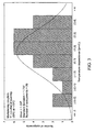
Fig. 3 is a graphic representation of results obtained in the stabilization of couplers in accordance with the present invention; and -
Fig. 4 is a graphic representation of results obtained in the stabilization of filters in accordance with the present invention. - The fiber optic component suitable for temperature stabilization in accordance with the present invention, such as a coupler or a filter or another type of waveguide interferometer, is produced on a setup such as shown in
Fig. 1 , which has twofiber holders motorized stages fibers arrows middle portion 26 heated by aheat source 28.Stages middle portion 26, as well as a good control of the pulling speed produced bymotorized stages - The
fiber holders fibers heat source 28 so that the desired longitudinal profile of the component may be reproduced from one fabrication to another and so that substrate elongation always produces the same shift in the component. For couplers or other components where at least two fibers are elongated, specialmechanical alignment devices fibers middle region 26. However, for fiber filters or tapers, only a single fiber is needed and thus only the positioning is important. - The
heat source 28, which inFig. 1 is shown to be a microtorch, could also be another suitable source, such as a small oven, a heating element or a laser, such as a CO2 laser that may be focused on different parts of the taper profile in theregion 26. Such a heat source should be mounted on amotorized stage 34 to allow it to move in x, y, z directions as shown by arrows x, y and z and thereby vary the heat pattern and position along the taper inregion 26 to enable a precise shaping of the longitudinal profile of the component The set-up may also have a protective shell (not shown) to limit undesired air movements around the heated fiber section. - The operation of the set-up illustrated in
Fig. 1 is as follows: - After the
fibers middle section 26, thefibers holders positioning stage 34 of theheat source 28 and the fiber holder stages 14, 16 is used to bring the heat source close to the fibers. In a coupler, the fibers are fused with a predetermined fusion profile, usually a few millimeters long. This fusion profile constitutes one of the parameters that should be adjusted to match both the wavelength properties and the mechanical properties of the coupler. In a fiber filter, there is no fusion step, since only one fiber is used. - The next step for both the coupler and the filter is the elongation. The flame is brought close enough to the fibers to make them ductile. The motors (not shown) actuating the
stages - In a coupler, it is important to realize an adiabatic profile, that is, a profile that has a taper slope small enough not to produce any coupling with higher order optical modes, which would in the end translate into undesired loss. To achieve this, a wide enough flame is required and one can brush the torch back and forth along the length to simulate a larger flame. One important thing in profile design is that the brush width can be varied during the elongation and this will change the profile shape and thus the mechanical and wavelength properties. For filters, the same torch control is also used, but one must create at one point in the process, some non-adiabatic regions to create the modal interferometer that gives the wavelength filtering properties to the components. For both the filter and the coupler, the elongation process is stopped when the desired wavelength period and phase are achieved.
- Once the desired component, such as a coupler or a filter, is produced as described above, it is secured to a chosen substrate as shown in
Fig. 2 . In this figure, thecomponent 36 is shown to be secured to therigid substrate 38 byadhesive bonds fibers component 36 and therigid substrate 38 should be strong enough to impart upon the component the thermal expansion of the substrate. Thesubstrate 38 is then inserted into a protective tube (not shown) or otherwise packaged. It should be noted that the bonding between the protective tube or package and the substrate should be supple, so that any unmatched temperature effect between the tube or package and the substrate does not affect the substrate. - Thus, in the design of a temperature compensating arrangement in accordance with the present invention, one must consider the fact that both the wavelength properties and the mechanical properties of the tapered component depend on the longitudinal taper shape. Thus, as opposed to Bragg gratings, where the thermal response depends on the fiber itself, tapered components with different longitudinal profiles, i.e., different wavelength periods and wavelengths, will have different temperature responses. One must thus develop the temperature compensating package of tapered components on a case by case basis. However, for components which have similar optical properties and longitudinal profiles, one can produce a new package by just making small modifications to a known functioning package and a person versed in the art can easily adapt the invention for his/her specific application.
- Two non-limitative examples are provided by way of preferred embodiments of the present invention. The first example relates to a coupler with a 11µm channel separation (1460-1471µm) and the second to a sine-filter with a 1.6µm channel separation at 1600µm.
- To achieve the temperature compensation, it is necessary to match the substrate elongation response to the component response. To know the component response, one can just bond the component to a quartz substrate. Since quartz has the same expansion coefficient (5.5 x 10⁻⁷/°C) as the fused silica of the fiber, the substrate does not induce any compensation effect Components bonded to a quartz substrate exhibit a shift towards the longer wavelength as the temperature increases. To produce a compensating elongation, the substrate should have a thermal expansion coefficient greater than quartz. For practical stock management reasons, it was decided to have a limited number of materials that have thermal expansion coefficient greater than quartz. For the couplers and filters fabricated herein, two types of silica glass were chosen, called type I and type II respectively, one with a thermal expansion coefficient of 13 x 10-7/°C and the other of 18 x 10-7/°C, which were found adequate for the compensation for the purposes of the present invention.
- Using these materials as the rigid substrate on which the component is mounted, a taper profile of the component is designed to produce the appropriate stress, given the substrate used, to insure the desired temperature compensation effect Moreover, this profile, as indicated previously, should provide the required wavelength response for the coupler.
- The profile design can be carried out in the following manner:
- A standard profile is made to achieve approximately the desired wavelength response. Such a component is then bonded onto a type I substrate. The component spectral response is measured as a function of temperature, i.e. from -20°C to +70°C and the temperature shift is established If the temperature shift is positive, the design does not provide enough temperature compensation and is under-compensated. If the shift is negative, then the design provides too much compensation and is overcompensated
- In the event of under-compensation, one can do several things, namely:
- (a) choose a substrate with a larger temperature expansion coefficient, such as the type II glass; this selection is normally used if the under-compensation is large;
- (b) place the two
bonding points - (c) change the taper profile of the component to be more sensitive to strain; this can be done by designing a profile with a smaller waist, but it must be carefully done so as not to change the wavelength response of the component.
- In the event of over-compensation, the following options are available:
- (a) choose a substrate with a smaller expansion coefficient;
- (b) place the bond points 42, 44 closer to each other, creating a lesser pulling effect; however, one may be limited here by the total taper distance, because the bond points should not be in the taper region;
- (c) make the waist of the taper profile larger, which causes the component to become larger.
- The above described process can be iterated to obtain the smallest possible thermal shift. Also, this iterative process can be used if one desires to obtain a predetermined non-zero wavelength shift.
- The two examples performed pursuant to this invention are summarized below:
- Twenty five multiplexing couplers with 11 µm channel spacing were produced. The tapered structure was elongated 33 mm to achieve proper wavelength spacing. The components were bonded to a 65 mm substrate of type I glass. The distance between the bond points was approximately 50 mm. The results are summarized in
Fig. 3 where the spectral response of the components was measured between -20°C and +70°C and the temperature dependence in picometers per °C is given for the various components, with the curve indicating the mean value which in this case is 1.237 pm/°C. The statistical standard deviation is 1.737 pm/°C for this example. It should be noted that in prior art couplers now on the market, temperature dependence is generally 8 - 10 pm/°C and thus the temperature stabilized coupler of the present invention constitutes a considerable improvement over the prior art. - Thirty sine filters with 3.2 µm period were produced. The tapered structure was elongated 35 µm to achieve proper wavelength spacing. The components were bonded to a 70 mm substrate of type II glass. The distance between the bond points was approximately 55 mm. The results are summarized in
Fig. 4 where the spectral response of the components was measured between 0°C and +70°C and the temperature dependence in picometers per °C is given for the various components, with the curve indicating the mean value which in this case is 0.619 pm/°C. The standard deviation is 1.219 pm/°C for this example. It should be noted that in prior art filters now on the market, temperature dependence is generally 10-15 pm/°C and thus the temperature stabilized filter of the present invention constitutes a considerable improvement over the prior art. - As the above examples demonstrate, every component needs a particular temperature stabilization design. However, once a proper design is established for a given component, it may only require a small modification to achieve stabilization if the change in the taper profile is small. It is thus fairly easy to adapt the design in accordance with the present invention to the various components.
- It should be noted that the invention is not limited to the specifically described embodiments and examples, but that various modifications obvious to those skilled in the art can be made without departing from the scope of the following claims.
Claims (16)
- A temperature stabilized tapered fiber optic component (36) formed by fusion and/or tapering of optical fibers (18, 20) creating a taper profile with a mechanical phase dependence and a predetermined wavelength response, characterised in that the component is strongly bonded at its extremities to a rigid substrate made of a material having a thermal expansion coefficient greater than quartz and producing a mechanical stress adapted to compensate for any modal phase shift of the component due to temperature variation by matching substrate elongation response to: the component wavelength response; and/or to the mechanical phase dependence of the component's taper profile.
- A temperature stabilized tapered fiber optic component according to claim 1, in which the rigid substrate is made of silica glass having a thermal expansion coefficient greater than quartz.
- A temperature stabilized tapered fiber optic component according to claims 1 or 2, in which the substrate elongation response is determined by the following equation:

where Is is the substrate elongation; d is the distance between bond points of the component to the substrate; K is the thermal expansion coefficient of the substrate; and ΔT is the temperature variation. - A temperature stabilized tapered fiber optic component according to claim 1, in which the mechanical phase dependence of the component is changed by changing the taper profile of the component without significantly affecting the wavelength response of the component.
- A temperature stabilized tapered fiber, optic component according to any one of claims 1 to 4, in which both the rigid substrate with the compensating mechanical stress and a change in the mechanical phase dependence of the component are used to achieve the desired temperature compensating effect.
- A temperature stabilized tapered fiber optic component according to any one of claims 1 to 5, which, together with the rigid substrate to which it is bonded, is enclosed in a protective tube or other suitable package that is not strongly connected to the substrate and does not produce a further compensating effect on the component due to temperature variation.
- A temperature stabilized tapered fiber optic component according to any one of claims 1 to 6, which is a fused fiber coupler formed with at least two optical fibers.
- A temperature stabilized tapered fiber optic component according to any one of claims 1 to 6, which is a fiber filter formed with a single optical fiber.
- Method of temperature stabilization of tapered fiber optic components (36), which comprises:(a) fusing and/or tapering optical fibers (18, 20) to form a tapered fiber optic component having a taper profile with a mechanical phase dependence and a predetermined wavelength response;(b) firmly securing said component to a rigid substrate by strongly bonding it to the substrate at each end of the component;(c) selecting a material for said substrate that has a thermal expansion coefficient greater than quartz and produces a predetermined mechanical stress such as to compensate for any modal phase shift of the component due to temperature variation by matching substrate elongation response to: the component wavelength response; and/or to the mechanical phase dependence of the component's taper profile.
- Method according to claim 9, which comprises both selecting the material for said substrate that produces the predetermined mechanical stress and adjusting the mechanical phase dependence of the component in relation to the substrate.
- Method according to claims 9 or 10, which comprises adjusting the distance between bond points of the component on the substrate to create a larger or lesser pulling effect.
- Method according to claims 9 or 10, which comprises adjusting the taper profile of the component to achieve a closer temperature compensating effect.
- Method according to any one of claims 9 to 12, which comprises iterating the process to obtain minimal thermal shift or a predetermined non-zero wavelength shift.
- Method according to any one of claims 9 to 13, further comprising enclosing the component bonded to the rigid substrate in a protective tube or package without strongly connecting the substrate to the tube or package.
- Method according to any one of claims 9 to 14, comprising fusing and tapering at least two optical fibers to form a temperature stabilized fiber optic coupler.
- Method according to any one of claims 9 to 15, comprising tapering a single optical fiber to form a fiber optic filter.
Applications Claiming Priority (3)
| Application Number | Priority Date | Filing Date | Title |
|---|---|---|---|
| CA002276859A CA2276859C (en) | 1999-06-29 | 1999-06-29 | Temperature stabilization of tapered fiber optic components |
| CA2276859 | 1999-06-29 | ||
| PCT/CA2000/000604 WO2001002886A1 (en) | 1999-06-29 | 2000-05-24 | Temperature stabilization of tapered fiber optic components |
Publications (2)
| Publication Number | Publication Date |
|---|---|
| EP1194802A1 EP1194802A1 (en) | 2002-04-10 |
| EP1194802B1 true EP1194802B1 (en) | 2008-07-23 |
Family
ID=4163681
Family Applications (1)
| Application Number | Title | Priority Date | Filing Date |
|---|---|---|---|
| EP00930920A Expired - Lifetime EP1194802B1 (en) | 1999-06-29 | 2000-05-24 | Temperature stabilization of tapered fiber optic components |
Country Status (9)
| Country | Link |
|---|---|
| US (1) | US6658182B1 (en) |
| EP (1) | EP1194802B1 (en) |
| JP (1) | JP4468618B2 (en) |
| KR (1) | KR100745246B1 (en) |
| AT (1) | ATE402421T1 (en) |
| CA (1) | CA2276859C (en) |
| DE (1) | DE60039606D1 (en) |
| IL (1) | IL147042A0 (en) |
| WO (1) | WO2001002886A1 (en) |
Families Citing this family (70)
| Publication number | Priority date | Publication date | Assignee | Title |
|---|---|---|---|---|
| CA2342098C (en) * | 2001-03-23 | 2008-08-26 | Itf Optical Technologies Inc.-Technologies Optiques Itf Inc. | Optical filter device for temperature dependence control |
| US6856730B2 (en) | 2002-07-22 | 2005-02-15 | Intel Corporation | Athermal package for fiber Bragg gratings with two or more bonding regions |
| JP2004325623A (en) * | 2003-04-23 | 2004-11-18 | Sumitomo Electric Ind Ltd | Optical fiber fusion splice reinforcement device and fusion splice reinforcement method |
| US7608092B1 (en) | 2004-02-20 | 2009-10-27 | Biomet Sports Medicince, LLC | Method and apparatus for performing meniscus repair |
| US8361113B2 (en) | 2006-02-03 | 2013-01-29 | Biomet Sports Medicine, Llc | Method and apparatus for coupling soft tissue to a bone |
| US8118836B2 (en) | 2004-11-05 | 2012-02-21 | Biomet Sports Medicine, Llc | Method and apparatus for coupling soft tissue to a bone |
| US8137382B2 (en) | 2004-11-05 | 2012-03-20 | Biomet Sports Medicine, Llc | Method and apparatus for coupling anatomical features |
| US8128658B2 (en) | 2004-11-05 | 2012-03-06 | Biomet Sports Medicine, Llc | Method and apparatus for coupling soft tissue to bone |
| US8840645B2 (en) | 2004-11-05 | 2014-09-23 | Biomet Sports Medicine, Llc | Method and apparatus for coupling soft tissue to a bone |
| US9801708B2 (en) | 2004-11-05 | 2017-10-31 | Biomet Sports Medicine, Llc | Method and apparatus for coupling soft tissue to a bone |
| US8298262B2 (en) | 2006-02-03 | 2012-10-30 | Biomet Sports Medicine, Llc | Method for tissue fixation |
| US8303604B2 (en) | 2004-11-05 | 2012-11-06 | Biomet Sports Medicine, Llc | Soft tissue repair device and method |
| US7601165B2 (en) | 2006-09-29 | 2009-10-13 | Biomet Sports Medicine, Llc | Method and apparatus for forming a self-locking adjustable suture loop |
| US7909851B2 (en) | 2006-02-03 | 2011-03-22 | Biomet Sports Medicine, Llc | Soft tissue repair device and associated methods |
| US7749250B2 (en) | 2006-02-03 | 2010-07-06 | Biomet Sports Medicine, Llc | Soft tissue repair assembly and associated method |
| US7905903B2 (en) | 2006-02-03 | 2011-03-15 | Biomet Sports Medicine, Llc | Method for tissue fixation |
| US8088130B2 (en) | 2006-02-03 | 2012-01-03 | Biomet Sports Medicine, Llc | Method and apparatus for coupling soft tissue to a bone |
| US20060189993A1 (en) | 2004-11-09 | 2006-08-24 | Arthrotek, Inc. | Soft tissue conduit device |
| US7905904B2 (en) | 2006-02-03 | 2011-03-15 | Biomet Sports Medicine, Llc | Soft tissue repair device and associated methods |
| US9017381B2 (en) | 2007-04-10 | 2015-04-28 | Biomet Sports Medicine, Llc | Adjustable knotless loops |
| US7857830B2 (en) | 2006-02-03 | 2010-12-28 | Biomet Sports Medicine, Llc | Soft tissue repair and conduit device |
| US8998949B2 (en) | 2004-11-09 | 2015-04-07 | Biomet Sports Medicine, Llc | Soft tissue conduit device |
| US8562647B2 (en) | 2006-09-29 | 2013-10-22 | Biomet Sports Medicine, Llc | Method and apparatus for securing soft tissue to bone |
| US8771352B2 (en) | 2011-05-17 | 2014-07-08 | Biomet Sports Medicine, Llc | Method and apparatus for tibial fixation of an ACL graft |
| US8801783B2 (en) | 2006-09-29 | 2014-08-12 | Biomet Sports Medicine, Llc | Prosthetic ligament system for knee joint |
| US8251998B2 (en) | 2006-08-16 | 2012-08-28 | Biomet Sports Medicine, Llc | Chondral defect repair |
| US9468433B2 (en) | 2006-02-03 | 2016-10-18 | Biomet Sports Medicine, Llc | Method and apparatus for forming a self-locking adjustable loop |
| US8597327B2 (en) | 2006-02-03 | 2013-12-03 | Biomet Manufacturing, Llc | Method and apparatus for sternal closure |
| US8562645B2 (en) | 2006-09-29 | 2013-10-22 | Biomet Sports Medicine, Llc | Method and apparatus for forming a self-locking adjustable loop |
| US9271713B2 (en) | 2006-02-03 | 2016-03-01 | Biomet Sports Medicine, Llc | Method and apparatus for tensioning a suture |
| US9078644B2 (en) | 2006-09-29 | 2015-07-14 | Biomet Sports Medicine, Llc | Fracture fixation device |
| US8506597B2 (en) | 2011-10-25 | 2013-08-13 | Biomet Sports Medicine, Llc | Method and apparatus for interosseous membrane reconstruction |
| US9149267B2 (en) | 2006-02-03 | 2015-10-06 | Biomet Sports Medicine, Llc | Method and apparatus for coupling soft tissue to a bone |
| US8968364B2 (en) | 2006-02-03 | 2015-03-03 | Biomet Sports Medicine, Llc | Method and apparatus for fixation of an ACL graft |
| US11259792B2 (en) | 2006-02-03 | 2022-03-01 | Biomet Sports Medicine, Llc | Method and apparatus for coupling anatomical features |
| US7959650B2 (en) | 2006-09-29 | 2011-06-14 | Biomet Sports Medicine, Llc | Adjustable knotless loops |
| US9538998B2 (en) | 2006-02-03 | 2017-01-10 | Biomet Sports Medicine, Llc | Method and apparatus for fracture fixation |
| US8652171B2 (en) | 2006-02-03 | 2014-02-18 | Biomet Sports Medicine, Llc | Method and apparatus for soft tissue fixation |
| US10517587B2 (en) | 2006-02-03 | 2019-12-31 | Biomet Sports Medicine, Llc | Method and apparatus for forming a self-locking adjustable loop |
| US11311287B2 (en) | 2006-02-03 | 2022-04-26 | Biomet Sports Medicine, Llc | Method for tissue fixation |
| US8574235B2 (en) | 2006-02-03 | 2013-11-05 | Biomet Sports Medicine, Llc | Method for trochanteric reattachment |
| US8652172B2 (en) | 2006-02-03 | 2014-02-18 | Biomet Sports Medicine, Llc | Flexible anchors for tissue fixation |
| US8672969B2 (en) | 2006-09-29 | 2014-03-18 | Biomet Sports Medicine, Llc | Fracture fixation device |
| US8500818B2 (en) | 2006-09-29 | 2013-08-06 | Biomet Manufacturing, Llc | Knee prosthesis assembly with ligament link |
| US9918826B2 (en) | 2006-09-29 | 2018-03-20 | Biomet Sports Medicine, Llc | Scaffold for spring ligament repair |
| US11259794B2 (en) | 2006-09-29 | 2022-03-01 | Biomet Sports Medicine, Llc | Method for implanting soft tissue |
| US12502169B2 (en) | 2007-01-16 | 2025-12-23 | Biomet Sports Medicine, Llc | Soft tissue repair device and associated methods |
| US7726876B2 (en) | 2007-03-14 | 2010-06-01 | Entegris, Inc. | System and method for non-intrusive thermal monitor |
| US12419632B2 (en) | 2008-08-22 | 2025-09-23 | Biomet Sports Medicine, Llc | Method and apparatus for coupling anatomical features |
| US12245759B2 (en) | 2008-08-22 | 2025-03-11 | Biomet Sports Medicine, Llc | Method and apparatus for coupling soft tissue to bone |
| US8343227B2 (en) | 2009-05-28 | 2013-01-01 | Biomet Manufacturing Corp. | Knee prosthesis assembly with ligament link |
| US12096928B2 (en) | 2009-05-29 | 2024-09-24 | Biomet Sports Medicine, Llc | Method and apparatus for coupling soft tissue to a bone |
| US12551209B2 (en) | 2009-06-22 | 2026-02-17 | Biomet Sports Medicine, Llc | Method and apparatus for coupling soft tissue to a bone |
| US12616462B2 (en) | 2009-09-30 | 2026-05-05 | Biomet Sports Medicine, Llc | Soft tissue repair device and method |
| US12329373B2 (en) | 2011-05-02 | 2025-06-17 | Biomet Sports Medicine, Llc | Method and apparatus for soft tissue fixation |
| US12582395B2 (en) | 2011-11-03 | 2026-03-24 | Biomet Sports Medicine, Llc | Method and apparatus for forming a self-locking adjustable loop |
| US9357991B2 (en) | 2011-11-03 | 2016-06-07 | Biomet Sports Medicine, Llc | Method and apparatus for stitching tendons |
| US9381013B2 (en) | 2011-11-10 | 2016-07-05 | Biomet Sports Medicine, Llc | Method for coupling soft tissue to a bone |
| US9370350B2 (en) | 2011-11-10 | 2016-06-21 | Biomet Sports Medicine, Llc | Apparatus for coupling soft tissue to a bone |
| US9357992B2 (en) | 2011-11-10 | 2016-06-07 | Biomet Sports Medicine, Llc | Method for coupling soft tissue to a bone |
| US9259217B2 (en) | 2012-01-03 | 2016-02-16 | Biomet Manufacturing, Llc | Suture Button |
| US9757119B2 (en) | 2013-03-08 | 2017-09-12 | Biomet Sports Medicine, Llc | Visual aid for identifying suture limbs arthroscopically |
| US9918827B2 (en) | 2013-03-14 | 2018-03-20 | Biomet Sports Medicine, Llc | Scaffold for spring ligament repair |
| US10136886B2 (en) | 2013-12-20 | 2018-11-27 | Biomet Sports Medicine, Llc | Knotless soft tissue devices and techniques |
| US9615822B2 (en) | 2014-05-30 | 2017-04-11 | Biomet Sports Medicine, Llc | Insertion tools and method for soft anchor |
| US9700291B2 (en) | 2014-06-03 | 2017-07-11 | Biomet Sports Medicine, Llc | Capsule retractor |
| US10039543B2 (en) | 2014-08-22 | 2018-08-07 | Biomet Sports Medicine, Llc | Non-sliding soft anchor |
| US9955980B2 (en) | 2015-02-24 | 2018-05-01 | Biomet Sports Medicine, Llc | Anatomic soft tissue repair |
| US9974534B2 (en) | 2015-03-31 | 2018-05-22 | Biomet Sports Medicine, Llc | Suture anchor with soft anchor of electrospun fibers |
| CN106970442B (en) * | 2017-05-12 | 2023-03-14 | 深圳大学 | Phase shift grating based on tapered fiber and its manufacturing method |
Family Cites Families (12)
| Publication number | Priority date | Publication date | Assignee | Title |
|---|---|---|---|---|
| US4867524A (en) * | 1988-09-08 | 1989-09-19 | United Technologies Corporation | Metallic bond for mounting of optical fibers to integrated optical chips |
| JP3031426B2 (en) * | 1990-04-16 | 2000-04-10 | 日本電信電話株式会社 | Waveguide type optical branching device |
| JPH0534540A (en) | 1991-08-01 | 1993-02-12 | Sumitomo Electric Ind Ltd | Reinforcement method of optical fiber coupler |
| US5243680A (en) | 1992-06-01 | 1993-09-07 | Soane Technologies, Inc. | Package for optical fiber couplers |
| JPH06222238A (en) | 1993-01-21 | 1994-08-12 | Sumitomo Electric Ind Ltd | Optical fiber coupler protection structure and protection method |
| US5367589A (en) | 1993-10-22 | 1994-11-22 | At&T Bell Laboratories | Optical fiber package |
| GB9323226D0 (en) * | 1993-11-10 | 1994-01-05 | Northern Telecom Ltd | Optical fibre elements |
| GB2299683A (en) * | 1995-04-04 | 1996-10-09 | Northern Telecom Ltd | Optical notch filter manufacture in a single mode fibre |
| US5971629A (en) * | 1996-07-12 | 1999-10-26 | Bloom; Cary | Apparatus and method bonding optical fiber and/or device to external element using compliant material interface |
| CN1060572C (en) * | 1996-11-13 | 2001-01-10 | 陈祖培 | Pyrometric cone high density wave divided multiplexing device |
| US5841920A (en) * | 1997-03-18 | 1998-11-24 | Lucent Technologies Inc. | Fiber grating package |
| US6081641A (en) * | 1997-11-03 | 2000-06-27 | Applied Fiber Optics, Inc. | Thermal compensated fused-fiber dense wavelength division multiplexer |
-
1999
- 1999-06-29 CA CA002276859A patent/CA2276859C/en not_active Expired - Lifetime
-
2000
- 2000-05-24 AT AT00930920T patent/ATE402421T1/en not_active IP Right Cessation
- 2000-05-24 KR KR1020017016805A patent/KR100745246B1/en not_active Expired - Lifetime
- 2000-05-24 EP EP00930920A patent/EP1194802B1/en not_active Expired - Lifetime
- 2000-05-24 JP JP2001508630A patent/JP4468618B2/en not_active Expired - Lifetime
- 2000-05-24 IL IL14704200A patent/IL147042A0/en not_active IP Right Cessation
- 2000-05-24 WO PCT/CA2000/000604 patent/WO2001002886A1/en not_active Ceased
- 2000-05-24 US US10/030,563 patent/US6658182B1/en not_active Expired - Lifetime
- 2000-05-24 DE DE60039606T patent/DE60039606D1/en not_active Expired - Lifetime
Also Published As
| Publication number | Publication date |
|---|---|
| JP2003504660A (en) | 2003-02-04 |
| EP1194802A1 (en) | 2002-04-10 |
| ATE402421T1 (en) | 2008-08-15 |
| KR100745246B1 (en) | 2007-08-01 |
| CA2276859A1 (en) | 2000-12-29 |
| CA2276859C (en) | 2006-01-17 |
| IL147042A0 (en) | 2002-08-14 |
| US6658182B1 (en) | 2003-12-02 |
| WO2001002886A1 (en) | 2001-01-11 |
| DE60039606D1 (en) | 2008-09-04 |
| KR20020016861A (en) | 2002-03-06 |
| JP4468618B2 (en) | 2010-05-26 |
Similar Documents
| Publication | Publication Date | Title |
|---|---|---|
| US6658182B1 (en) | Temperature stabilization of tapered fiber optic components | |
| CA2353408C (en) | Strain-isolated bragg grating temperature sensor | |
| US6321006B2 (en) | Optical fiber having an expanded mode field diameter and method of expanding the mode field diameter of an optical fiber | |
| EP0606583B1 (en) | Achromatic optical fiber coupler | |
| CA2209710C (en) | Compact tunable wavelength independent all-fiber optical attenuator and method of making same | |
| US6865194B1 (en) | Strain-isolated Bragg grating temperature sensor | |
| CA2641193A1 (en) | Optical fiber fundamental mode field expander | |
| EP0416537B1 (en) | Optical fiber coupler | |
| JP2010224577A (en) | Fabrication of multiplexing and demultiplexing single-mode fiber optic coupler | |
| AU3779200A (en) | Method of manufacturing polarization-maintaining optical fiber coupler | |
| US5652819A (en) | Method for tuning fiber optic couplers and multiplexers | |
| US6529671B2 (en) | Passively compensated optical fibers | |
| TW200411235A (en) | Athermal package for fiber bragg gratings with two or more bonding regions | |
| US20020146230A1 (en) | Temperature-compensating arrangements and methods for optical fiber | |
| KR100200939B1 (en) | Fiber optic coupler | |
| US7065267B2 (en) | Athermal fused coupler package for optical fibers | |
| WO1987003702A1 (en) | Optical fiber coupler used as wdm | |
| MXPA01003139A (en) | An optical fiber having an expanded mode field diameter and method of expanding the modefield diameter of an optical fiber | |
| JPH08220369A (en) | Optical fiber coupler and manufacturing method thereof | |
| JP2003177257A (en) | Optical fiber for long period grating, long period grating component and method of manufacturing the same | |
| MXPA01005408A (en) | Strain-isolated bragg grating temperature sensor | |
| JP2005345516A (en) | Manufacturing method of optical fiber coupler | |
| JP2003075680A (en) | Fusion type optical fiber coupler |
Legal Events
| Date | Code | Title | Description |
|---|---|---|---|
| PUAI | Public reference made under article 153(3) epc to a published international application that has entered the european phase |
Free format text: ORIGINAL CODE: 0009012 |
|
| 17P | Request for examination filed |
Effective date: 20020129 |
|
| AK | Designated contracting states |
Kind code of ref document: A1 Designated state(s): AT BE CH CY DE DK ES FI FR GB GR IE IT LI LU MC NL PT SE |
|
| AX | Request for extension of the european patent |
Free format text: AL;LT;LV;MK;RO;SI |
|
| GRAP | Despatch of communication of intention to grant a patent |
Free format text: ORIGINAL CODE: EPIDOSNIGR1 |
|
| RAP1 | Party data changed (applicant data changed or rights of an application transferred) |
Owner name: ITF LABORATORIES INC. |
|
| GRAS | Grant fee paid |
Free format text: ORIGINAL CODE: EPIDOSNIGR3 |
|
| GRAA | (expected) grant |
Free format text: ORIGINAL CODE: 0009210 |
|
| AK | Designated contracting states |
Kind code of ref document: B1 Designated state(s): AT BE CH CY DE DK ES FI FR GB GR IE IT LI LU MC NL PT SE |
|
| REG | Reference to a national code |
Ref country code: GB Ref legal event code: FG4D |
|
| REG | Reference to a national code |
Ref country code: CH Ref legal event code: EP |
|
| REG | Reference to a national code |
Ref country code: IE Ref legal event code: FG4D |
|
| REF | Corresponds to: |
Ref document number: 60039606 Country of ref document: DE Date of ref document: 20080904 Kind code of ref document: P |
|
| NLV1 | Nl: lapsed or annulled due to failure to fulfill the requirements of art. 29p and 29m of the patents act | ||
| PG25 | Lapsed in a contracting state [announced via postgrant information from national office to epo] |
Ref country code: PT Free format text: LAPSE BECAUSE OF FAILURE TO SUBMIT A TRANSLATION OF THE DESCRIPTION OR TO PAY THE FEE WITHIN THE PRESCRIBED TIME-LIMIT Effective date: 20081223 Ref country code: ES Free format text: LAPSE BECAUSE OF FAILURE TO SUBMIT A TRANSLATION OF THE DESCRIPTION OR TO PAY THE FEE WITHIN THE PRESCRIBED TIME-LIMIT Effective date: 20081103 Ref country code: NL Free format text: LAPSE BECAUSE OF FAILURE TO SUBMIT A TRANSLATION OF THE DESCRIPTION OR TO PAY THE FEE WITHIN THE PRESCRIBED TIME-LIMIT Effective date: 20080723 |
|
| PG25 | Lapsed in a contracting state [announced via postgrant information from national office to epo] |
Ref country code: AT Free format text: LAPSE BECAUSE OF FAILURE TO SUBMIT A TRANSLATION OF THE DESCRIPTION OR TO PAY THE FEE WITHIN THE PRESCRIBED TIME-LIMIT Effective date: 20080723 Ref country code: FI Free format text: LAPSE BECAUSE OF FAILURE TO SUBMIT A TRANSLATION OF THE DESCRIPTION OR TO PAY THE FEE WITHIN THE PRESCRIBED TIME-LIMIT Effective date: 20080723 |
|
| PG25 | Lapsed in a contracting state [announced via postgrant information from national office to epo] |
Ref country code: BE Free format text: LAPSE BECAUSE OF FAILURE TO SUBMIT A TRANSLATION OF THE DESCRIPTION OR TO PAY THE FEE WITHIN THE PRESCRIBED TIME-LIMIT Effective date: 20080723 |
|
| PG25 | Lapsed in a contracting state [announced via postgrant information from national office to epo] |
Ref country code: DK Free format text: LAPSE BECAUSE OF FAILURE TO SUBMIT A TRANSLATION OF THE DESCRIPTION OR TO PAY THE FEE WITHIN THE PRESCRIBED TIME-LIMIT Effective date: 20080723 |
|
| PLBE | No opposition filed within time limit |
Free format text: ORIGINAL CODE: 0009261 |
|
| STAA | Information on the status of an ep patent application or granted ep patent |
Free format text: STATUS: NO OPPOSITION FILED WITHIN TIME LIMIT |
|
| 26N | No opposition filed |
Effective date: 20090424 |
|
| PG25 | Lapsed in a contracting state [announced via postgrant information from national office to epo] |
Ref country code: MC Free format text: LAPSE BECAUSE OF NON-PAYMENT OF DUE FEES Effective date: 20090531 |
|
| REG | Reference to a national code |
Ref country code: CH Ref legal event code: PL |
|
| PG25 | Lapsed in a contracting state [announced via postgrant information from national office to epo] |
Ref country code: CH Free format text: LAPSE BECAUSE OF NON-PAYMENT OF DUE FEES Effective date: 20090531 Ref country code: SE Free format text: LAPSE BECAUSE OF FAILURE TO SUBMIT A TRANSLATION OF THE DESCRIPTION OR TO PAY THE FEE WITHIN THE PRESCRIBED TIME-LIMIT Effective date: 20081023 Ref country code: LI Free format text: LAPSE BECAUSE OF NON-PAYMENT OF DUE FEES Effective date: 20090531 |
|
| PG25 | Lapsed in a contracting state [announced via postgrant information from national office to epo] |
Ref country code: IE Free format text: LAPSE BECAUSE OF NON-PAYMENT OF DUE FEES Effective date: 20090524 |
|
| PG25 | Lapsed in a contracting state [announced via postgrant information from national office to epo] |
Ref country code: GR Free format text: LAPSE BECAUSE OF FAILURE TO SUBMIT A TRANSLATION OF THE DESCRIPTION OR TO PAY THE FEE WITHIN THE PRESCRIBED TIME-LIMIT Effective date: 20081024 |
|
| PG25 | Lapsed in a contracting state [announced via postgrant information from national office to epo] |
Ref country code: LU Free format text: LAPSE BECAUSE OF NON-PAYMENT OF DUE FEES Effective date: 20090524 |
|
| PG25 | Lapsed in a contracting state [announced via postgrant information from national office to epo] |
Ref country code: CY Free format text: LAPSE BECAUSE OF FAILURE TO SUBMIT A TRANSLATION OF THE DESCRIPTION OR TO PAY THE FEE WITHIN THE PRESCRIBED TIME-LIMIT Effective date: 20080723 |
|
| REG | Reference to a national code |
Ref country code: FR Ref legal event code: PLFP Year of fee payment: 16 |
|
| REG | Reference to a national code |
Ref country code: FR Ref legal event code: TP Owner name: ITF TECHNOLOGIES INC., CA Effective date: 20160330 |
|
| REG | Reference to a national code |
Ref country code: FR Ref legal event code: PLFP Year of fee payment: 17 |
|
| REG | Reference to a national code |
Ref country code: FR Ref legal event code: PLFP Year of fee payment: 18 |
|
| REG | Reference to a national code |
Ref country code: FR Ref legal event code: PLFP Year of fee payment: 19 |
|
| PGFP | Annual fee paid to national office [announced via postgrant information from national office to epo] |
Ref country code: IT Payment date: 20190527 Year of fee payment: 20 Ref country code: DE Payment date: 20190521 Year of fee payment: 20 |
|
| PGFP | Annual fee paid to national office [announced via postgrant information from national office to epo] |
Ref country code: FR Payment date: 20190522 Year of fee payment: 20 |
|
| PGFP | Annual fee paid to national office [announced via postgrant information from national office to epo] |
Ref country code: GB Payment date: 20190430 Year of fee payment: 20 |
|
| REG | Reference to a national code |
Ref country code: DE Ref legal event code: R071 Ref document number: 60039606 Country of ref document: DE |
|
| REG | Reference to a national code |
Ref country code: GB Ref legal event code: PE20 Expiry date: 20200523 |
|
| PG25 | Lapsed in a contracting state [announced via postgrant information from national office to epo] |
Ref country code: GB Free format text: LAPSE BECAUSE OF EXPIRATION OF PROTECTION Effective date: 20200523 |