EP1194652B1 - Auger piling - Google Patents
Auger pilingInfo
- Publication number
- EP1194652B1 EP1194652B1 EP01931937A EP01931937A EP1194652B1 EP 1194652 B1 EP1194652 B1 EP 1194652B1 EP 01931937 A EP01931937 A EP 01931937A EP 01931937 A EP01931937 A EP 01931937A EP 1194652 B1 EP1194652 B1 EP 1194652B1
- Authority
- EP
- European Patent Office
- Prior art keywords
- auger
- monitoring device
- drive mechanism
- ground
- continuous flight
- Prior art date
- Legal status (The legal status is an assumption and is not a legal conclusion. Google has not performed a legal analysis and makes no representation as to the accuracy of the status listed.)
- Expired - Lifetime
Links
Images


Classifications
-
- E—FIXED CONSTRUCTIONS
- E21—EARTH OR ROCK DRILLING; MINING
- E21B—EARTH OR ROCK DRILLING; OBTAINING OIL, GAS, WATER, SOLUBLE OR MELTABLE MATERIALS OR A SLURRY OF MINERALS FROM WELLS
- E21B44/00—Automatic control systems specially adapted for drilling operations, i.e. self-operating systems which function to carry out or modify a drilling operation without intervention of a human operator, e.g. computer-controlled drilling systems; Systems specially adapted for monitoring a plurality of drilling variables or conditions
- E21B44/02—Automatic control of the tool feed
- E21B44/04—Automatic control of the tool feed in response to the torque of the drive ; Measuring drilling torque
-
- E—FIXED CONSTRUCTIONS
- E02—HYDRAULIC ENGINEERING; FOUNDATIONS; SOIL SHIFTING
- E02D—FOUNDATIONS; EXCAVATIONS; EMBANKMENTS; UNDERGROUND OR UNDERWATER STRUCTURES
- E02D33/00—Testing foundations or foundation structures
-
- E—FIXED CONSTRUCTIONS
- E02—HYDRAULIC ENGINEERING; FOUNDATIONS; SOIL SHIFTING
- E02D—FOUNDATIONS; EXCAVATIONS; EMBANKMENTS; UNDERGROUND OR UNDERWATER STRUCTURES
- E02D5/00—Bulkheads, piles, or other structural elements specially adapted to foundation engineering
- E02D5/22—Piles
- E02D5/34—Concrete or concrete-like piles cast in position ; Apparatus for making same
- E02D5/36—Concrete or concrete-like piles cast in position ; Apparatus for making same making without use of mouldpipes or other moulds
Definitions
- This invention relates to auger piling, and in particular the monitoring of a continuous flight auger piling process.
- Continuous flight auger piling has been used in the construction industry in increasing volume since the early 1980's. Piles are constructed by drilling to the required depth with a continuous flight auger mounted on a piling rig. During withdrawal of the auger, concrete grout or slurry is pumped into the excavated hole through the auger. A steel reinforcement cage may subsequently be lowered into the pile, either under its own weight or with the assistance of a vibrator.
- the auger is rotated into the ground at a rate intended to minimise the disturbance of the ground.
- the rate of advance of the auger during boring should depend upon the nature of the soil so as to cause this minimum disturbance.
- One indication of the nature of the ground is provided by measuring the torque on the auger during the boring process. This has conventionally been achieved by means of feedback signals from the drive motor.
- the rate of withdrawal of the auger should be sufficiently low that the appropriate amount of concrete can be delivered through the auger.
- the rate of extraction and/or the flow rate of supplied concrete also need to be controlled to prevent collapse of soil from the walls of the excavation, which would contaminate the concrete cross section. It is known to monitor the concrete pressure in the concrete feed pipe at a suitable location in order to ensure that concrete is being supplied to the auger tip during the extraction process. A positive concrete pressure is maintained as the auger is withdrawn.
- US 3 300 988, EP 0 940 505 and WO 97/05334 each disclose auger piling rigs in which pressure feedback signals are provided from the auger tip for use in the control of the piling process.
- US 4 285 236 discloses an oil well drilling rig in which the rotational speed of, and the rotary torque applied to, the drill string are monitored to optimize drilling and to observe pipe sticking and other effects.
- a monitoring device for a continuous flight auger comprising a shaft for connection between a continuous flight auger and a drive mechanism or for connection between adjacent auger sections, the shaft comprising a coupling at each end for connection to respective couplings of the drive mechanism and/or of the auger such that the shaft rotates with the auger, wherein the device further comprises a strain measurement arrangement for providing strain signals for use in deriving the rotational torque and axial force of the auger, and wherein the device further comprises means for evaluating ground conditions from the torque and force, for use in controlling the rotational speed and/or advance of the auger into the ground.
- the invention provides an additional section to be mounted either at the top of the auger or between auger sections for direct measurement of the rotational torque and axial force on the auger during the piling process.
- the monitoring device may remain above ground level if mounted adjacent the drive mechanism, or may be mounted part way down the auger.
- the axial strain information can be used in combination with the rotational torque to build up a model of the ground.
- the shear strength of the soil determines the maximum pile capacity
- the axial strain can be used to determine the soil shear strength, to enable pile capacity to be determined without a detailed site investigation.
- the strain measurement arrangement may comprise a plurality of strain gauges disposed around the shaft.
- the monitoring device preferably also comprises a pressure detection device for mounting at the lower end of the auger and a connection arrangement for coupling signals from the pressure detection device to a receiver of the monitoring device.
- connection arrangement may comprise a hydraulic line.
- a hydraulic connection can easily be provided between auger sections for a multi-section auger.
- the pressure measurement is then achieved by a pressure transducer mounted above ground on the monitoring device, for example on the shaft.
- the pressure detection device comprises an electrical pressure transducer coupled to the receiver by an electrical line.
- the receiver may comprise a radio transmitter for sending measured data to a control station.
- the data from the monitoring device provides data which enables a predictive judgement of pile capacity on completion of the pile.
- the data may also be used as an aid for the rig driver in controlling the process.
- an automatically controlled process may be envisaged.
- the invention also provides a control device for controlling the driving of a continuous flight auger, comprising a monitoring device of the invention and a control means for providing control signals for the control of the drive mechanism in dependence on signals provided by the monitoring device.
- An automatically controlled continuous flight auger rig of the invention uses this control device.
- the auger may comprise a core and a flight, in which the core comprises two concentric walls.
- a hydraulic line for transmitting pressure signals from the lower end of the auger may be defined using the spacing between the concentric walls of the core.
- FIG. 1 shows an auger rig 10 of the invention for performing a continuous flight auger piling operation.
- the rig 10 shown in Figure 1 includes one section 11a of a multiple section continuous flight, hollow-shafted auger 11 which is rotatably mounted on a drive mechanism 12 which is in turn mounted for vertical movement on an upright pillar 13.
- the auger section 11a is one of many selectively attachable auger sections. Typically, each auger section 11a will have a length of approximately 6m, whereas the desired depth of the concrete pile will usually be between 10m and 26m.
- the auger sections are arranged to be attached to each other by appropriate couplings. The auger sections may be connected together before commencing the piling or alternatively, for very deep piling or in limited headroom circumstances, drilling the full length cavity may be performed in short incremental stages.
- the drive mechanism 12 includes a depth encoder for determining the depth of penetration of the auger into the ground. Furthermore, concrete is supplied to the auger by a supply system including a flow meter.
- a monitoring device 14 is provided in the form of a shaft which is coupled for rotation with the auger.
- one monitoring device is provided between the auger 11 and the drive mechanism 12.
- the device 14 may instead be provided between auger sections, and more than one such device may be provided.
- one monitoring device may be provided adjacent the drive mechanism, and one may be provided near the bottom tip of the auger.
- the device 14 may comprise an auger section, and thus be provided with a flight, or it may comprise a short section with no flight, as shown in the drawings.
- the shaft 14 has a coupling 15 at each end for connection to a coupling of the drive mechanism 12 and/or of the auger 11.
- the monitoring device 14 is connected to rotate with the auger 11 and has a strain measurement arrangement providing strain signals which enable the rotational torque and axial force of the auger to be derived.
- the strain measurement arrangement measures circumferential and axial strain.
- This torque and force data can be used to control the rotational speed and/or the advance of the auger 11 into the ground as a function of the ground conditions.
- the auger is controlled so that the flights of the auger are kept loaded with soil originating from the auger tip 19. This can be achieved by evaluating the ground conditions based on the resistance presented to the auger by the ground, which influences the rotational torque and the axial strain in the auger. This information is provided by the monitoring device 14, which gives more accurate information concerning the ground conditions than the measurement of parameters relating to the motor of the drive mechanism 12.
- the soil shear stress may be calculated by pulling back on the auger whilst maintaining rotation. Measurement of the axial strain together with the rotational torque can enable the shear stress of the soil to be calculated. This can be carried out incrementally as the depth is increased to build up a model of the soil characteristics.
- the invention provides a modular system.
- the monitoring device is provided with standard connections at each end, so that is may be used with any auger piling system following this standard.
- the tip 19 of the auger is provided with a pressure detection device, and the signals from the detection device are coupled to a receiver at the top of the auger, in the region of the monitoring device 14.
- the pressure detection device is used during the extraction of the auger to ensure the presence of concrete at the tip 19.
- the pressure detection device may comprise a chamber having a deformable membrane which is exposed to the concrete at the tip 19. The pressure exerted on the membrane is transmitted by a hydraulic line to a pressure transducer located above ground level.
- an electrical pressure transducer may be provided at the tip 19 with coupling using an electrical cable to a monitoring device at the head of the auger.
- a further possibility is to provide the pressure transducer at the tip of the auger with a radio transmitter, so as to avoid the need to provide electrical cable connections at the junctions between auger sections.
- the monitoring device at the head of the auger would then be provided with a appropriate receiver.
- Figure 2 shows a second auger section 11b introduced between the first auger section 11a and the monitoring device 14.
- the two auger sections 11a, 11b may be assembled before piling commences, and a monitoring unit of the invention may be provided between the auger sections instead of or as well as the monitoring device at the head of the auger.
- connection 20 between the auger sections 11a, 11b must include an appropriate connector for the pressure detection device signals. When radio transmission is provided, this is not required.
- Figure 3 is used to illustrate the steps of the continuous flight auger piling process.
- the auger 11 is rotated and allowed to advance into the ground.
- the data from the monitoring device may also be used as an aid for the rig driver in controlling the piling process.
- a control device which provides control signals for the control of the drive mechanism 12. This may be used to alter the rotational speed and/or the rate of advance of the auger 11 into the ground.
- the pressure detection device in the tip 19 of the auger is used either by the rig driver, or by the automatic control system, to ensure that there is a constant supply of concrete to the auger tip 19.
- the auger 11 is progressively withdrawn from the bore by a hydraulic lifting mechanism forming part of the drive mechanism 12.
- the drive mechanism 12 is controlled to vary the rate of auger withdrawal, again either manually or automatically. In either case, the rate of withdrawal can be a function of the concrete flow rate and the pressure signal provided by the pressure detection device.
- the representation at 26 shows almost complete withdrawal of the auger 11, and with optional reinforcement added a completed pile is shown at 28.
- the data obtained from the monitoring device 14 can be used to control the piling process, as described above. However, the data alternatively or additionally may be used to enable a predictive judgement of pile capacity on completion of the pile.
- FIG. 4 shows in greater detail the monitoring device 14 of the invention.
- the device comprises a shaft 30 with a male spigot connector 15a at one end and a female corresponding bore 15b at the other end.
- the spigot 15a has a hexagonal cross section and torque is transmitted by the spigot-bore connection between the monitoring device 14 and the adjacent auger 11 as well as between the monitoring device 14 and the adjacent drive mechanism 12.
- strain gauges 32 are provided on the surface of the shaft 30. The axial strain through the shaft and the torque vary as the depth of the bore increases and also vary as the nature of the soil at the tip 19 changes.
- strain gauges to provide torque and axial strain information.
- an arrangement of at least two surface-mounted strain gauges may be employed, in a configuration enabling torque and axial strain to be resolved. This may be a diamond configuration of strain gauges.
- the monitoring device 14 is also provided with a receiver 34 which receives the signal from the pressure detection device located at the tip 19.
- the receiver 34 comprises a pressure transducer which communicates with a hydraulic line running the entire length of the auger and communicating with a diaphragm at the auger tip 19.
- an electrical system is also possible.
- the signals from all of the strain gauges and the pressure receiver 34 are preferably provided by a radio link to a central computer in the cab of the piling rig machine.
- a data collection and transmission device 36 for this purpose is shown schematically in Figure 5.
- a commutator arrangement may be used, which enables the signals to be tapped off the monitoring device 14 to an appropriate control device (not shown).
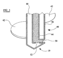
- Figure 5 shows in greater detail the design of the tip 19 of one possible auger construction 11, which comprises a core 40 and a flight 42.
- the core 40 comprises inner and outer skins 44, 46.
- the inner skin 44 defines the passage for the supply of concrete 48 and extends to an opening 50 adjacent the tip 19.
- the opening 50 is shown provided at a lateral position to reduce the likelihood of blockage.
- the space between the inner and outer skins 44, 46 defines a chamber which runs the entire length of the auger 11. This chamber is used to define the hydraulic line coupling the pressure detection device 52 and the receiver 34 located at the monitoring device 14.
- the pressure detection device 52 comprises a membrane, as shown in Figure 5, which is responsive to the pressure at the auger tip 19.
- the auger construction of Figure 5 is a double skin auger, and a pressure sensor with hydraulic signal coupling is provided. Of course, a single skin auger may also be chosen.
- the invention provides improved monitoring of the auger conditions during a continuous flight auger piling process, which can improve the quality of the concrete pile formed.
- the monitoring device can be inserted into existing piling rigs without significant modification to those existing systems, at least in the case of the strain measurement systems associated with the monitoring device 14.
Landscapes
- Engineering & Computer Science (AREA)
- Life Sciences & Earth Sciences (AREA)
- Mining & Mineral Resources (AREA)
- Structural Engineering (AREA)
- General Life Sciences & Earth Sciences (AREA)
- Paleontology (AREA)
- General Engineering & Computer Science (AREA)
- Geology (AREA)
- Civil Engineering (AREA)
- Fluid Mechanics (AREA)
- Geochemistry & Mineralogy (AREA)
- Physics & Mathematics (AREA)
- Environmental & Geological Engineering (AREA)
- Earth Drilling (AREA)
- Organic Low-Molecular-Weight Compounds And Preparation Thereof (AREA)
- Working-Up Tar And Pitch (AREA)
- Golf Clubs (AREA)
- Electrical Discharge Machining, Electrochemical Machining, And Combined Machining (AREA)
- Placing Or Removing Of Piles Or Sheet Piles, Or Accessories Thereof (AREA)
Abstract
Description
- This invention relates to auger piling, and in particular the monitoring of a continuous flight auger piling process.
- Continuous flight auger piling has been used in the construction industry in increasing volume since the early 1980's. Piles are constructed by drilling to the required depth with a continuous flight auger mounted on a piling rig. During withdrawal of the auger, concrete grout or slurry is pumped into the excavated hole through the auger. A steel reinforcement cage may subsequently be lowered into the pile, either under its own weight or with the assistance of a vibrator.
- During the initial boring stage, the auger is rotated into the ground at a rate intended to minimise the disturbance of the ground. The rate of advance of the auger during boring should depend upon the nature of the soil so as to cause this minimum disturbance. One indication of the nature of the ground is provided by measuring the torque on the auger during the boring process. This has conventionally been achieved by means of feedback signals from the drive motor.
- During extraction, the rate of withdrawal of the auger should be sufficiently low that the appropriate amount of concrete can be delivered through the auger. The rate of extraction and/or the flow rate of supplied concrete also need to be controlled to prevent collapse of soil from the walls of the excavation, which would contaminate the concrete cross section. It is known to monitor the concrete pressure in the concrete feed pipe at a suitable location in order to ensure that concrete is being supplied to the auger tip during the extraction process. A positive concrete pressure is maintained as the auger is withdrawn.
- However, positive pressure readings can result even when insufficient concrete has been delivered, for example as a result of blockages to the concrete supply pipe. It is desirable therefore to provide pressure measurement at the bottom end of the auger instead of in the supply pipe further upstream.
- Difficulties then arise in establishing the connections to a pressure transducer located at the lower end of the auger to a control device. These problems are particularly severe when the auger is arranged as a multi-section device, since the coupling between auger sections also requires a coupling to be provided for the pressure transducer signal line. This line would be exposed to adverse conditions during the piling process.
- US 3 300 988, EP 0 940 505 and WO 97/05334 each disclose auger piling rigs in which pressure feedback signals are provided from the auger tip for use in the control of the piling process.
- US 4 285 236 discloses an oil well drilling rig in which the rotational speed of, and the rotary torque applied to, the drill string are monitored to optimize drilling and to observe pipe sticking and other effects.
- According to the present invention, there is provided a monitoring device for a continuous flight auger, comprising a shaft for connection between a continuous flight auger and a drive mechanism or for connection between adjacent auger sections, the shaft comprising a coupling at each end for connection to respective couplings of the drive mechanism and/or of the auger such that the shaft rotates with the auger, wherein the device further comprises a strain measurement arrangement for providing strain signals for use in deriving the rotational torque and axial force of the auger, and wherein the device further comprises means for evaluating ground conditions from the torque and force, for use in controlling the rotational speed and/or advance of the auger into the ground.
- The invention provides an additional section to be mounted either at the top of the auger or between auger sections for direct measurement of the rotational torque and axial force on the auger during the piling process. The monitoring device may remain above ground level if mounted adjacent the drive mechanism, or may be mounted part way down the auger.
- The axial strain information can be used in combination with the rotational torque to build up a model of the ground. In particular, the shear strength of the soil determines the maximum pile capacity, and the axial strain can be used to determine the soil shear strength, to enable pile capacity to be determined without a detailed site investigation.
- The strain measurement arrangement may comprise a plurality of strain gauges disposed around the shaft.
- The monitoring device preferably also comprises a pressure detection device for mounting at the lower end of the auger and a connection arrangement for coupling signals from the pressure detection device to a receiver of the monitoring device.
- This enables measurement of the pressure at the lower end of the auger to ensure the correct supply of concrete. The connection arrangement may comprise a hydraulic line. A hydraulic connection can easily be provided between auger sections for a multi-section auger. The pressure measurement is then achieved by a pressure transducer mounted above ground on the monitoring device, for example on the shaft.
- Alternatively, the pressure detection device comprises an electrical pressure transducer coupled to the receiver by an electrical line.
- The receiver may comprise a radio transmitter for sending measured data to a control station.
- The data from the monitoring device provides data which enables a predictive judgement of pile capacity on completion of the pile. However, the data may also be used as an aid for the rig driver in controlling the process. Alternatively, an automatically controlled process may be envisaged. In this respect, the invention also provides a control device for controlling the driving of a continuous flight auger, comprising a monitoring device of the invention and a control means for providing control signals for the control of the drive mechanism in dependence on signals provided by the monitoring device. An automatically controlled continuous flight auger rig of the invention uses this control device.
- The auger may comprise a core and a flight, in which the core comprises two concentric walls. In this case, a hydraulic line for transmitting pressure signals from the lower end of the auger may be defined using the spacing between the concentric walls of the core.
- An example of the invention will now be described in detail with reference to the accompanying drawings, in which:
- Figure 1 shows a continuous flight auger piling rig, with one section of a multiple section auger assembled on the rig;
- Figure 2 shows the apparatus of Figure 1 in which a second auger section has been added;
- Figure 3 is a diagram showing the operation of the continuous flight auger piling process;
- Figure 4 shows in greater detail the monitoring device of the invention; and
- Figure 5 shows in greater detail a pressure detection device for mounting at the tip of the auger with hydraulic coupling.
- Figure 1 shows an
auger rig 10 of the invention for performing a continuous flight auger piling operation. Therig 10 shown in Figure 1 includes one section 11a of a multiple section continuous flight, hollow-shaftedauger 11 which is rotatably mounted on adrive mechanism 12 which is in turn mounted for vertical movement on anupright pillar 13. The auger section 11a is one of many selectively attachable auger sections. Typically, each auger section 11a will have a length of approximately 6m, whereas the desired depth of the concrete pile will usually be between 10m and 26m. The auger sections are arranged to be attached to each other by appropriate couplings. The auger sections may be connected together before commencing the piling or alternatively, for very deep piling or in limited headroom circumstances, drilling the full length cavity may be performed in short incremental stages. - The
drive mechanism 12 includes a depth encoder for determining the depth of penetration of the auger into the ground. Furthermore, concrete is supplied to the auger by a supply system including a flow meter. - In accordance with the invention, a
monitoring device 14 is provided in the form of a shaft which is coupled for rotation with the auger. In the example shown in the drawings, one monitoring device is provided between theauger 11 and thedrive mechanism 12. Thedevice 14 may instead be provided between auger sections, and more than one such device may be provided. For example, one monitoring device may be provided adjacent the drive mechanism, and one may be provided near the bottom tip of the auger. - The
device 14 may comprise an auger section, and thus be provided with a flight, or it may comprise a short section with no flight, as shown in the drawings. - The
shaft 14 has acoupling 15 at each end for connection to a coupling of thedrive mechanism 12 and/or of theauger 11. Themonitoring device 14 is connected to rotate with theauger 11 and has a strain measurement arrangement providing strain signals which enable the rotational torque and axial force of the auger to be derived. For this purpose, the strain measurement arrangement measures circumferential and axial strain. - This torque and force data can be used to control the rotational speed and/or the advance of the
auger 11 into the ground as a function of the ground conditions. Preferably, the auger is controlled so that the flights of the auger are kept loaded with soil originating from theauger tip 19. This can be achieved by evaluating the ground conditions based on the resistance presented to the auger by the ground, which influences the rotational torque and the axial strain in the auger. This information is provided by themonitoring device 14, which gives more accurate information concerning the ground conditions than the measurement of parameters relating to the motor of thedrive mechanism 12. - Different techniques may be employed for driving the auger into the soil. For example, the soil shear stress may be calculated by pulling back on the auger whilst maintaining rotation. Measurement of the axial strain together with the rotational torque can enable the shear stress of the soil to be calculated. This can be carried out incrementally as the depth is increased to build up a model of the soil characteristics.
- The invention provides a modular system. The monitoring device is provided with standard connections at each end, so that is may be used with any auger piling system following this standard.
- The
tip 19 of the auger is provided with a pressure detection device, and the signals from the detection device are coupled to a receiver at the top of the auger, in the region of themonitoring device 14. The pressure detection device is used during the extraction of the auger to ensure the presence of concrete at thetip 19. - In the case that multiple monitoring devices are provided, only one will need to have an associated pressure detection device.
- The pressure detection device may comprise a chamber having a deformable membrane which is exposed to the concrete at the
tip 19. The pressure exerted on the membrane is transmitted by a hydraulic line to a pressure transducer located above ground level. - Alternatively, an electrical pressure transducer may be provided at the
tip 19 with coupling using an electrical cable to a monitoring device at the head of the auger. A further possibility is to provide the pressure transducer at the tip of the auger with a radio transmitter, so as to avoid the need to provide electrical cable connections at the junctions between auger sections. The monitoring device at the head of the auger would then be provided with a appropriate receiver. - Figure 2 shows a second auger section 11b introduced between the first auger section 11a and the
monitoring device 14. The two auger sections 11a, 11b may be assembled before piling commences, and a monitoring unit of the invention may be provided between the auger sections instead of or as well as the monitoring device at the head of the auger. - When there is a physical conductor of signals from the pressure detection device at the
tip 19 and the monitoring device 14 (a hydraulic or electrical line), theconnection 20 between the auger sections 11a, 11b must include an appropriate connector for the pressure detection device signals. When radio transmission is provided, this is not required. - Figure 3 is used to illustrate the steps of the continuous flight auger piling process. During drilling stage shown at 22, the
auger 11 is rotated and allowed to advance into the ground. The data from the monitoring device may also be used as an aid for the rig driver in controlling the piling process. - Alternatively, an automatically controlled process may be envisaged. In this case, a control device is provided which provides control signals for the control of the
drive mechanism 12. This may be used to alter the rotational speed and/or the rate of advance of theauger 11 into the ground. - Once the
auger 11 has advanced to the required depth, concrete is pumped through theauger 11 as shown at 24. The concrete flow rate is monitored by the concrete supply system. - The pressure detection device in the
tip 19 of the auger is used either by the rig driver, or by the automatic control system, to ensure that there is a constant supply of concrete to theauger tip 19. Theauger 11 is progressively withdrawn from the bore by a hydraulic lifting mechanism forming part of thedrive mechanism 12. Thedrive mechanism 12 is controlled to vary the rate of auger withdrawal, again either manually or automatically. In either case, the rate of withdrawal can be a function of the concrete flow rate and the pressure signal provided by the pressure detection device. - The representation at 26 shows almost complete withdrawal of the
auger 11, and with optional reinforcement added a completed pile is shown at 28. - The data obtained from the
monitoring device 14 can be used to control the piling process, as described above. However, the data alternatively or additionally may be used to enable a predictive judgement of pile capacity on completion of the pile. - Figure 4 shows in greater detail the
monitoring device 14 of the invention. The device comprises ashaft 30 with a male spigot connector 15a at one end and a female corresponding bore 15b at the other end. In the example shown, the spigot 15a has a hexagonal cross section and torque is transmitted by the spigot-bore connection between themonitoring device 14 and theadjacent auger 11 as well as between themonitoring device 14 and theadjacent drive mechanism 12. In order to measure the rotational torque and axial strain in theauger 11, strain gauges 32 are provided on the surface of theshaft 30. The axial strain through the shaft and the torque vary as the depth of the bore increases and also vary as the nature of the soil at thetip 19 changes. - It will be apparent to those skilled in the art how to mount the strain gauges to provide torque and axial strain information. Typically an arrangement of at least two surface-mounted strain gauges may be employed, in a configuration enabling torque and axial strain to be resolved. This may be a diamond configuration of strain gauges.
- The
monitoring device 14 is also provided with areceiver 34 which receives the signal from the pressure detection device located at thetip 19. In one example, thereceiver 34 comprises a pressure transducer which communicates with a hydraulic line running the entire length of the auger and communicating with a diaphragm at theauger tip 19. As described above, an electrical system is also possible. - The signals from all of the strain gauges and the
pressure receiver 34 are preferably provided by a radio link to a central computer in the cab of the piling rig machine. A data collection andtransmission device 36 for this purpose is shown schematically in Figure 5. As an alternative, a commutator arrangement may be used, which enables the signals to be tapped off themonitoring device 14 to an appropriate control device (not shown). - Figure 5 shows in greater detail the design of the
tip 19 of onepossible auger construction 11, which comprises acore 40 and aflight 42. Thecore 40 comprises inner andouter skins inner skin 44 defines the passage for the supply ofconcrete 48 and extends to anopening 50 adjacent thetip 19. Theopening 50 is shown provided at a lateral position to reduce the likelihood of blockage. The space between the inner andouter skins auger 11. This chamber is used to define the hydraulic line coupling thepressure detection device 52 and thereceiver 34 located at themonitoring device 14. In its simplest form, thepressure detection device 52 comprises a membrane, as shown in Figure 5, which is responsive to the pressure at theauger tip 19. - The auger construction of Figure 5 is a double skin auger, and a pressure sensor with hydraulic signal coupling is provided. Of course, a single skin auger may also be chosen.
- The invention provides improved monitoring of the auger conditions during a continuous flight auger piling process, which can improve the quality of the concrete pile formed. The monitoring device can be inserted into existing piling rigs without significant modification to those existing systems, at least in the case of the strain measurement systems associated with the
monitoring device 14. - Various modifications will be apparent to those skilled in the art. Similarly, the exact construction of the piling rig and of the concrete supply and flow monitoring equipment has not been described in detail, since this is all conventional in the art.
Claims (14)
- A monitoring device (14) for a continuous flight auger, comprising a shaft (30) for connection between a continuous flight auger (11) and a drive mechanism (12) or for connection between adjacent auger sections, the shaft comprising a coupling (15) at each end for connection to respective couplings of the drive mechanism (12) and/or of the auger (11) such that the shaft rotates with the auger,
characterised in that the device further comprises a strain measurement arrangement (32) for providing strain signals for use in deriving the rotational torque and axial force of the auger, and in that the device further comprises means for evaluating ground conditions from the torque and force, for use in controlling the rotational speed and/or advance of the auger into the ground. - A device as claimed in claim 1, wherein the ground conditions comprise the shear stress of the ground.
- A device as claimed in claim 1 or 2, wherein the strain measurement arrangement comprises a plurality of strain gauges (32) disposed on the shaft.
- A device as claimed in claim 1, 2 or 3, further comprising a pressure detection device (52) for mounting at the lower end (19) of the auger (11), and a connection arrangement for coupling signals from the pressure detection device (52) to a receiver (34) of the monitoring device.
- A device as claimed in claim 4, wherein the connection arrangement comprises a hydraulic line.
- A device as claimed in claim 5, wherein the receiver (34) comprises a pressure transducer mounted on the shaft.
- A device as claimed in claim 4, wherein the pressure detection device comprises an electrical pressure transducer coupled to the receiver by an electrical line.
- A device as claimed in any one of claims 4 to 7, wherein the receiver comprises a radio transmitter for sending measured data to a control station.
- A continuous flight auger rig (10) comprising a continuous flight auger (11), a drive mechanism (12) for driving the auger into the ground, and a monitoring device (14) as claimed in any one of claims 1 to 8.
- A control device for controlling the driving of a continuous flight auger, comprising a monitoring device (14) as claimed in any one of claims 1 to 8, and a control means for providing control signals for the control of the drive mechanism (12) in dependence on signals provided by the monitoring device (14).
- A continuous flight auger rig (10) comprising a continuous flight auger (11), a drive mechanism (12) for driving the auger into the ground, and a control device for controlling the drive mechanism as claimed in claim 10.
- A rig (10) as claimed in claim 9 or 11, wherein the auger comprises a core (40) and a flight (42), the core comprising two concentric walls (44, 46).
- A rig (10) as claimed in claim 12, wherein the monitoring device comprises a pressure detection device (52) mounted at the lower end (19) of the auger (11), and a hydraulic line coupling signals from the pressure detection device to a pressure transducer (34) mounted on the shaft, and wherein the hydraulic line is defined by the spacing between the concentric walls (44, 46) of the core (40).
- A rig as claimed in any one of claims 9, 11, 12 or 13, in which the auger (11) comprises multiple sections (11a, 11b).
Applications Claiming Priority (3)
| Application Number | Priority Date | Filing Date | Title |
|---|---|---|---|
| GB0013015 | 2000-05-26 | ||
| GBGB0013015.3A GB0013015D0 (en) | 2000-05-26 | 2000-05-26 | Auger piling |
| PCT/GB2001/002326 WO2001090488A1 (en) | 2000-05-26 | 2001-05-23 | Auger piling |
Publications (2)
| Publication Number | Publication Date |
|---|---|
| EP1194652A1 EP1194652A1 (en) | 2002-04-10 |
| EP1194652B1 true EP1194652B1 (en) | 2006-10-04 |
Family
ID=9892546
Family Applications (1)
| Application Number | Title | Priority Date | Filing Date |
|---|---|---|---|
| EP01931937A Expired - Lifetime EP1194652B1 (en) | 2000-05-26 | 2001-05-23 | Auger piling |
Country Status (7)
| Country | Link |
|---|---|
| US (1) | US20030044241A1 (en) |
| EP (1) | EP1194652B1 (en) |
| AT (1) | ATE341667T1 (en) |
| AU (1) | AU5862301A (en) |
| DE (1) | DE60123545T2 (en) |
| GB (1) | GB0013015D0 (en) |
| WO (1) | WO2001090488A1 (en) |
Families Citing this family (15)
| Publication number | Priority date | Publication date | Assignee | Title |
|---|---|---|---|---|
| DE10354624B3 (en) * | 2003-11-22 | 2005-05-04 | Gudehus, Gerd, Prof. Dr.-Ing. | A method for plugging soft ground has a helical screw to bore the ground and to fill with stiffening material and whose rotational driving torque is monitored and controlled |
| US20080131211A1 (en) * | 2004-07-13 | 2008-06-05 | Nesmith Willie M | Installation effort deep foudnation method |
| FR2903435B1 (en) * | 2006-07-07 | 2008-08-29 | Jean Marie Renovation Sarl | DEVICE FOR MEASURING MICROPOWER RESISTANCE |
| NL2000160C2 (en) * | 2006-07-25 | 2008-01-28 | Geodynamic | Method for checking the bearing capacity of a pole. |
| GB2447491A (en) * | 2007-03-15 | 2008-09-17 | Roxbury Ltd | Pile Formation |
| US20100310321A1 (en) * | 2008-08-28 | 2010-12-09 | Petr Horanek | Pile for Foundation |
| GB2472234A (en) * | 2009-07-29 | 2011-02-02 | Gavin Rixon | Setting a ground anchor by using a strain gauge type device |
| US8845236B1 (en) * | 2013-02-15 | 2014-09-30 | FixDirt, LLC | Ground anchor |
| WO2014205527A1 (en) * | 2013-06-24 | 2014-12-31 | Sccap Engenharia Ltda | A system for monitoring the quality of execution of excavated piles and tunnel bores |
| ITFI20130199A1 (en) * | 2013-08-27 | 2015-02-27 | Silvio Giannini | EXTERNAL THREAD TUBES FOR LAND REINFORCEMENTS |
| DE102014225726A1 (en) * | 2014-12-12 | 2016-06-16 | Maik Kettner | Methods and devices for ground improvement |
| WO2017174860A1 (en) * | 2016-04-08 | 2017-10-12 | Junttan Oy | A method and an apparatus for determining the torque of an auger, and a pile driving rig |
| WO2019169180A1 (en) * | 2018-02-28 | 2019-09-06 | Aptim Intellectual Property Holdings, Llc | Pressure grouted displacement screw piles |
| BR112021016168B1 (en) * | 2019-02-28 | 2022-06-14 | Giken Ltd | PILING PRESSURE DEVICE AND PILING PRESSURE METHOD |
| US12258724B2 (en) * | 2021-07-05 | 2025-03-25 | Giken Ltd. | Pile press-in construction method, pile supplying device, and pile press-in device |
Family Cites Families (6)
| Publication number | Priority date | Publication date | Assignee | Title |
|---|---|---|---|---|
| US3300988A (en) * | 1960-12-23 | 1967-01-31 | Raymond Int Inc | Apparatus for forming piles |
| US4285236A (en) * | 1979-11-23 | 1981-08-25 | Dresser Industries, Inc. | Rotary torque and rpm indicator for oil well drilling rigs |
| US4662458A (en) * | 1985-10-23 | 1987-05-05 | Nl Industries, Inc. | Method and apparatus for bottom hole measurement |
| FR2677385A1 (en) * | 1991-06-05 | 1992-12-11 | Labrue Jean Marie | DEVICE FOR INJECTING AND CONTROLLING THE CONCRETE WORKING OF PILES WITH HOLLOW TARRIES. |
| GB2303868B (en) * | 1995-07-31 | 1999-04-14 | Cementation Piling & Found | Improved auger piling |
| DE29804010U1 (en) * | 1998-03-06 | 1998-06-25 | Bauer Spezialtiefbau Gmbh, 86529 Schrobenhausen | Device for creating a foundation element in the ground |
-
2000
- 2000-05-26 GB GBGB0013015.3A patent/GB0013015D0/en not_active Ceased
-
2001
- 2001-05-23 US US10/031,512 patent/US20030044241A1/en not_active Abandoned
- 2001-05-23 AU AU58623/01A patent/AU5862301A/en not_active Abandoned
- 2001-05-23 DE DE60123545T patent/DE60123545T2/en not_active Expired - Lifetime
- 2001-05-23 EP EP01931937A patent/EP1194652B1/en not_active Expired - Lifetime
- 2001-05-23 WO PCT/GB2001/002326 patent/WO2001090488A1/en not_active Ceased
- 2001-05-23 AT AT01931937T patent/ATE341667T1/en not_active IP Right Cessation
Also Published As
| Publication number | Publication date |
|---|---|
| DE60123545D1 (en) | 2006-11-16 |
| US20030044241A1 (en) | 2003-03-06 |
| ATE341667T1 (en) | 2006-10-15 |
| GB0013015D0 (en) | 2000-07-19 |
| AU5862301A (en) | 2001-12-03 |
| EP1194652A1 (en) | 2002-04-10 |
| WO2001090488A1 (en) | 2001-11-29 |
| DE60123545T2 (en) | 2007-08-16 |
Similar Documents
| Publication | Publication Date | Title |
|---|---|---|
| US20030044241A1 (en) | Auger piling | |
| US4941951A (en) | Method for improving a drilling process by characterizing the hydraulics of the drilling system | |
| US4445578A (en) | System for measuring downhole drilling forces | |
| US10344586B2 (en) | Drilling apparatus for producing a cased bore and method for operating a drilling apparatus | |
| US5833015A (en) | Method and apparatus for sinking pipes or cables into a pilot borehole | |
| US5632575A (en) | Method and apparatus for controlled pumping of bentonite around a pipe jacked tunnel | |
| NO335829B1 (en) | Procedure for preventing formation cracking | |
| AU2017355273B2 (en) | Flexible collar for a rotary steerable system | |
| US5010765A (en) | Method of monitoring core sampling during borehole drilling | |
| CN118564254A (en) | Grouting method for pipe jacking grouting system | |
| US6238142B1 (en) | Apparatus for erecting a foundation element in the ground | |
| CA1256297A (en) | Method and a device for feeding concrete into a drill hole in the concrete bolting of a rock | |
| JP7188768B2 (en) | Support layer determination system | |
| ZA200600073B (en) | Instrumented drill head, related drilling/bolting machines, and methods | |
| CN209855772U (en) | 4-3/4-inch integrated logging-while-drilling system | |
| JP6535614B2 (en) | Ground improvement construction machine | |
| KR101577326B1 (en) | Trenchless drilling apparatus having an auto-level feature | |
| GB2043747A (en) | Drilling boreholes | |
| KR100467753B1 (en) | An automatic control device of the amount of injecting grout for boring and grouting and the method thereof | |
| JP3850543B2 (en) | Self-boring pressure meter test method by wire line | |
| AU2020205242B2 (en) | Collar control system for mobile drilling machines | |
| JP3465006B2 (en) | Vertical hole wall condition measuring device | |
| KR200379065Y1 (en) | Level observation apparatus for excavator | |
| US20260092520A1 (en) | Adaptive collaring using rock fracture indication | |
| CN111395306B (en) | A system and method for judging and processing faults of strata when the plug-in board of a plug-in machine encounters obstacles |
Legal Events
| Date | Code | Title | Description |
|---|---|---|---|
| PUAI | Public reference made under article 153(3) epc to a published international application that has entered the european phase |
Free format text: ORIGINAL CODE: 0009012 |
|
| 17P | Request for examination filed |
Effective date: 20020204 |
|
| AK | Designated contracting states |
Kind code of ref document: A1 Designated state(s): AT BE CH CY DE DK ES FI FR GB GR IE IT LI LU MC NL PT SE TR |
|
| AX | Request for extension of the european patent |
Free format text: AL;LT;LV;MK;RO;SI |
|
| 17Q | First examination report despatched |
Effective date: 20030902 |
|
| GRAP | Despatch of communication of intention to grant a patent |
Free format text: ORIGINAL CODE: EPIDOSNIGR1 |
|
| GRAS | Grant fee paid |
Free format text: ORIGINAL CODE: EPIDOSNIGR3 |
|
| GRAA | (expected) grant |
Free format text: ORIGINAL CODE: 0009210 |
|
| AK | Designated contracting states |
Kind code of ref document: B1 Designated state(s): AT BE CH CY DE DK ES FI FR GB GR IE IT LI LU MC NL PT SE TR |
|
| PG25 | Lapsed in a contracting state [announced via postgrant information from national office to epo] |
Ref country code: NL Free format text: LAPSE BECAUSE OF FAILURE TO SUBMIT A TRANSLATION OF THE DESCRIPTION OR TO PAY THE FEE WITHIN THE PRESCRIBED TIME-LIMIT Effective date: 20061004 Ref country code: FI Free format text: LAPSE BECAUSE OF FAILURE TO SUBMIT A TRANSLATION OF THE DESCRIPTION OR TO PAY THE FEE WITHIN THE PRESCRIBED TIME-LIMIT Effective date: 20061004 Ref country code: AT Free format text: LAPSE BECAUSE OF FAILURE TO SUBMIT A TRANSLATION OF THE DESCRIPTION OR TO PAY THE FEE WITHIN THE PRESCRIBED TIME-LIMIT Effective date: 20061004 Ref country code: BE Free format text: LAPSE BECAUSE OF FAILURE TO SUBMIT A TRANSLATION OF THE DESCRIPTION OR TO PAY THE FEE WITHIN THE PRESCRIBED TIME-LIMIT Effective date: 20061004 Ref country code: LI Free format text: LAPSE BECAUSE OF FAILURE TO SUBMIT A TRANSLATION OF THE DESCRIPTION OR TO PAY THE FEE WITHIN THE PRESCRIBED TIME-LIMIT Effective date: 20061004 Ref country code: CH Free format text: LAPSE BECAUSE OF FAILURE TO SUBMIT A TRANSLATION OF THE DESCRIPTION OR TO PAY THE FEE WITHIN THE PRESCRIBED TIME-LIMIT Effective date: 20061004 |
|
| REG | Reference to a national code |
Ref country code: GB Ref legal event code: FG4D |
|
| REG | Reference to a national code |
Ref country code: CH Ref legal event code: EP |
|
| REG | Reference to a national code |
Ref country code: IE Ref legal event code: FG4D |
|
| REF | Corresponds to: |
Ref document number: 60123545 Country of ref document: DE Date of ref document: 20061116 Kind code of ref document: P |
|
| PG25 | Lapsed in a contracting state [announced via postgrant information from national office to epo] |
Ref country code: DK Free format text: LAPSE BECAUSE OF FAILURE TO SUBMIT A TRANSLATION OF THE DESCRIPTION OR TO PAY THE FEE WITHIN THE PRESCRIBED TIME-LIMIT Effective date: 20070104 Ref country code: SE Free format text: LAPSE BECAUSE OF FAILURE TO SUBMIT A TRANSLATION OF THE DESCRIPTION OR TO PAY THE FEE WITHIN THE PRESCRIBED TIME-LIMIT Effective date: 20070104 |
|
| PG25 | Lapsed in a contracting state [announced via postgrant information from national office to epo] |
Ref country code: ES Free format text: LAPSE BECAUSE OF FAILURE TO SUBMIT A TRANSLATION OF THE DESCRIPTION OR TO PAY THE FEE WITHIN THE PRESCRIBED TIME-LIMIT Effective date: 20070115 |
|
| PG25 | Lapsed in a contracting state [announced via postgrant information from national office to epo] |
Ref country code: PT Free format text: LAPSE BECAUSE OF FAILURE TO SUBMIT A TRANSLATION OF THE DESCRIPTION OR TO PAY THE FEE WITHIN THE PRESCRIBED TIME-LIMIT Effective date: 20070316 |
|
| NLV1 | Nl: lapsed or annulled due to failure to fulfill the requirements of art. 29p and 29m of the patents act | ||
| ET | Fr: translation filed | ||
| REG | Reference to a national code |
Ref country code: CH Ref legal event code: PL |
|
| PLBE | No opposition filed within time limit |
Free format text: ORIGINAL CODE: 0009261 |
|
| STAA | Information on the status of an ep patent application or granted ep patent |
Free format text: STATUS: NO OPPOSITION FILED WITHIN TIME LIMIT |
|
| 26N | No opposition filed |
Effective date: 20070705 |
|
| PG25 | Lapsed in a contracting state [announced via postgrant information from national office to epo] |
Ref country code: MC Free format text: LAPSE BECAUSE OF NON-PAYMENT OF DUE FEES Effective date: 20070531 |
|
| PG25 | Lapsed in a contracting state [announced via postgrant information from national office to epo] |
Ref country code: GR Free format text: LAPSE BECAUSE OF FAILURE TO SUBMIT A TRANSLATION OF THE DESCRIPTION OR TO PAY THE FEE WITHIN THE PRESCRIBED TIME-LIMIT Effective date: 20070105 |
|
| PG25 | Lapsed in a contracting state [announced via postgrant information from national office to epo] |
Ref country code: IE Free format text: LAPSE BECAUSE OF NON-PAYMENT OF DUE FEES Effective date: 20070523 |
|
| PG25 | Lapsed in a contracting state [announced via postgrant information from national office to epo] |
Ref country code: LU Free format text: LAPSE BECAUSE OF NON-PAYMENT OF DUE FEES Effective date: 20070523 Ref country code: CY Free format text: LAPSE BECAUSE OF FAILURE TO SUBMIT A TRANSLATION OF THE DESCRIPTION OR TO PAY THE FEE WITHIN THE PRESCRIBED TIME-LIMIT Effective date: 20061004 |
|
| PG25 | Lapsed in a contracting state [announced via postgrant information from national office to epo] |
Ref country code: TR Free format text: LAPSE BECAUSE OF FAILURE TO SUBMIT A TRANSLATION OF THE DESCRIPTION OR TO PAY THE FEE WITHIN THE PRESCRIBED TIME-LIMIT Effective date: 20061004 |
|
| PGFP | Annual fee paid to national office [announced via postgrant information from national office to epo] |
Ref country code: FR Payment date: 20100525 Year of fee payment: 10 |
|
| PGFP | Annual fee paid to national office [announced via postgrant information from national office to epo] |
Ref country code: IT Payment date: 20100517 Year of fee payment: 10 Ref country code: DE Payment date: 20100519 Year of fee payment: 10 |
|
| REG | Reference to a national code |
Ref country code: DE Ref legal event code: R119 Ref document number: 60123545 Country of ref document: DE |
|
| REG | Reference to a national code |
Ref country code: DE Ref legal event code: R119 Ref document number: 60123545 Country of ref document: DE |
|
| REG | Reference to a national code |
Ref country code: FR Ref legal event code: ST Effective date: 20120131 |
|
| PG25 | Lapsed in a contracting state [announced via postgrant information from national office to epo] |
Ref country code: IT Free format text: LAPSE BECAUSE OF NON-PAYMENT OF DUE FEES Effective date: 20110523 |
|
| PG25 | Lapsed in a contracting state [announced via postgrant information from national office to epo] |
Ref country code: FR Free format text: LAPSE BECAUSE OF NON-PAYMENT OF DUE FEES Effective date: 20110531 |
|
| PG25 | Lapsed in a contracting state [announced via postgrant information from national office to epo] |
Ref country code: DE Free format text: LAPSE BECAUSE OF NON-PAYMENT OF DUE FEES Effective date: 20111130 |
|
| PGFP | Annual fee paid to national office [announced via postgrant information from national office to epo] |
Ref country code: GB Payment date: 20200513 Year of fee payment: 20 |
|
| REG | Reference to a national code |
Ref country code: GB Ref legal event code: PE20 Expiry date: 20210522 |
|
| PG25 | Lapsed in a contracting state [announced via postgrant information from national office to epo] |
Ref country code: GB Free format text: LAPSE BECAUSE OF EXPIRATION OF PROTECTION Effective date: 20210522 |