EP1194004A1 - Electrostatic acoustic device - Google Patents
Electrostatic acoustic device Download PDFInfo
- Publication number
- EP1194004A1 EP1194004A1 EP00402687A EP00402687A EP1194004A1 EP 1194004 A1 EP1194004 A1 EP 1194004A1 EP 00402687 A EP00402687 A EP 00402687A EP 00402687 A EP00402687 A EP 00402687A EP 1194004 A1 EP1194004 A1 EP 1194004A1
- Authority
- EP
- European Patent Office
- Prior art keywords
- diaphragm
- electrode
- acoustic device
- electrostatic
- main portion
- Prior art date
- Legal status (The legal status is an assumption and is not a legal conclusion. Google has not performed a legal analysis and makes no representation as to the accuracy of the status listed.)
- Withdrawn
Links
Images

Classifications
-
- H—ELECTRICITY
- H04—ELECTRIC COMMUNICATION TECHNIQUE
- H04R—LOUDSPEAKERS, MICROPHONES, GRAMOPHONE PICK-UPS OR LIKE ACOUSTIC ELECTROMECHANICAL TRANSDUCERS; ELECTRIC HEARING AIDS; PUBLIC ADDRESS SYSTEMS
- H04R19/00—Electrostatic transducers
Definitions
- the present invention relates to an electrostatic acoustic device and especially to an electrostatic acoustic device having a first electrode for applying an electrical field, a diaphragm with a main portion, a peripheral portion and an elastic portion between the main portion and the peripheral portion and fixing means for fixing the peripheral portion of the diaphragm to the first electrode, wherein the main portion of the diaphragm is movable by the electrical field.
- Electrostatic acoustic devices in this context primarily include electrostatic loudspeakers or microphones.
- a typical electrostatic loudspeaker known in the art is shown in FIG. 1.
- sound pressure can be produced in correspondence with a driving signal by impressing a bias voltage, for instance direct current biasing, with the driving signal.
- a bias voltage for instance direct current biasing
- the driving signal 1 output from a power amplifier is boosted several times via a step-up transformer 2 an output signal of which is output to a speaker element 5.
- This speaker element 5 consists of stationary electrodes 6, 7 which are electrode plates having multiple holes, or perforations, therein. These stationary electrodes 6, 7 are arranged opposing each other with a prescribed distance therebetween.
- the output signal of the step-up transformer 2 is impressed between these stationary electrodes 6, 7.
- the speaker element 5 includes a diaphragm 8 forming the conductive fine filter on the polyester film for example, and maintains this diaphragm 8 between the stationary electrodes 6, 7.
- the bias voltage of several kV is formed by boosting the commercial power source at a high voltage bias circuit 3 and is applied between a secondary side middle tap of the step up transformer 2 and the diaphragm 8.
- the circuit 3 for forming the bias voltage impresses the bias voltage to the diaphragm 8 via resistor 4 having a prescribed resistance value.
- the sound pressure corresponding to the driving signal can be provided by elastically vibrating the diaphragm with this driving force F.
- ⁇ is the dielectric constant which, in this case, is 8.85 * 10 -12 [F/m]
- S is made up of the electrode area [m 2 ]
- E 0 and E are bias voltage [V] and voltage of driving signal [V] respectively
- d is a distance between the electrodes [m].
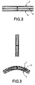
- the driving force F expressed by the above equation is produced on the entire diaphragm equally. Since the diaphragm is homogeneous and its outer circumference is fixedly hold, it is deformed to a circular arc shape and elastically vibrated as shown by the arrow in FIG. 2.
- spacers may be employed for limiting the diaphragm movement to avoid that the diaphragm touches the stationary electrodes.
- the bass response is limited by such spacers.
- the diaphragm is stretched in a frame and, therefore, is flat essentially. Due to such diaphragm shape, sherical dispersion is poor.
- a loudspeaker may have the shape of a portion of a cylinder.
- the horizontal and vertical profile of such loudspeaker are shown in FIG. 3 again the arrows indicate the movement of the diaphragm.
- DE-A-196 41 503 describes an electrostatic loudspeaker with circular dispersion characteristic.
- the electrodes and the diaphragm have the shape of a half ball.
- the periphery of the diaphragm is fixed to a ring by gluing.
- the object of the present invention to provide an electrostatic acoustic device enhanced electro-acoustic efficiency, whereby the diaphragm of the device does not touch the electrodes.
- an electrostatic acoustic device having a first electrode for applying an electrical field, a diaphragm with a main portion, a peripheral portion and an elastic portion between the main portion and the peripheral portion and fixing means for fixing the peripheral portion of the diaphragm to the first electrode, wherein the main portion of the diaphragm is movable by the electrical field, and wherein the elastic portion of the diaphragm is deformed during movement of the diaphragm, whereas the shape of the main portion of the diaphragm is essentially maintained, when substantially constant surface force is applied to the entire surface of the diaphragm by the electrical field.
- the elastic portion is deformable easier than other portions of the diaphragm.
- the elastic portion is deformed and the main portion of the diaphragm maintains its shape.
- the movement of the diaphragm is very linear, i.e. parallel to the electrodes, compared to the prior art. Consequently a loudspeaker using such technique has a better linear response.
- high sound pressure level is obtainable since the air volume vibrated by the diaphragm is similar to that of US-A-5,471,540.
- the electrostatic acoustic device further includes a second electrode positioned opposite to the first electrode, wherein the diaphragm is fixed between the first and the second electrode.
- the electrode or the electrodes as well as the diaphragm each may have the shape of a spherical, cylindrical or pyramidal dome. Such shape of the diaphragm would increase the low frequency range and high frequency range for reproduction, since these specific shapes strengthen the diaphragm tremendously. Additionally, thinner or lighter material can be used for the diaphragm compared to the prior art.
- dome shape of the diaphragm is the wide spatial dispersion and the easiness of production and handling of such diaphragm.
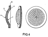
- FIG. 4 includes a sectional view of an electrostatic loudspeaker on the left side, a perspective view in the middle and a topview of the inventive loudspeaker on the right side.
- the inventive loudspeaker of FIG. 4 is built up with a first electrode 6, a second electrode 7 and a diaphragm 8 therebetween. Both electrodes are provided with throughholes so that the air vibrated by the diaphragm 8 can pass the electrodes 6 and 7.
- the diaphragm 8 is fixed between the electrodes 6 and 7 by fixing means 10. Thus, a parallel structure of the electrodes 6 and 7 and the diaphragm 8 is obtained.
- the fixing means 10 includes two fixing rings which also serve as spacers between the electrodes 6 and 7 and the diaphragm 8, respectively.
- the diaphragm 8 is sandwiched between the two fixing rings.
- the fixing means 10 is realized by two identical, electrically insulating rings.
- the fixing means 10 may also include ring sections, pins, bolts or the like. This means that the diaphragm may be fixed on a couple of points of its circumference.
- the diaphragm 8 may also include tongues at its periphery for fixing the diaphragm 8 to the fixing means 10.
- the fixing rings shown in FIG. 4 are integrally formed with the electrodes 6 and 7, so that the diaphragm 8 may be clamped between the electrodes, wherein electric insulation is provided by coating the electrodes 6 and 7 and/or the diaphragm 8.
- the fixing means may be part of one or both of the electrodes 6 and 7.
- the main part of the diaphragm 8 corresponds to a sphere section. At the periphery of the sphere section there is provided a collar. This collar is integral with the sphere section and represents an elastic portion 9. The function of this elastic portion 9 will be described in connection with FIG. 5, 6 and 7.
- FIG. 4 show a spherical dome shaped loudspeaker.
- a shaped loudspeaker has an improved spherical dispersion characteristic.
- loudspeakers with a flat diaphragm have poor spatial dispersion.
- loudspeakers of the one forth cylinder type have good horizontal but bad vertical dispersion.
- the shape of the dome may also be that of a pyramid, cone, ellipsoid, hyperboloid or the like.
- the advantage of the dome shaped diaphragm 8 is on the one hand that, as already mentioned, the spherical dispersion of the acoustic emission is improved compared to flat or cylindrical loudspeakers.
- the dome shape of the diaphragm 8 improves its mechanical strength. Therefore, the thickness of the diaphragm can be reduced to 0,02 mm or less.
- Such a thin diaphragm may be realized by a transparent mylar film which is very flexible. Additionally, lighter material for the diaphragm can be employed because of the inherent strength of the dome shape diaphragm.
- a further advantage of the dome shaped diaphragm 8 is that it must not be stretched between the electrodes to be kept centered between them.
- the dome shaped diaphragm has to be fixed only perpendicular to the surface or the diaphragm by spacers, for example. Thus, no or only very low central forces perpendicular to the moving direction are applied to the dome shaped diaphragm 8, so that the degree of freedom for choosing the material of the diaphragm is enlarged.
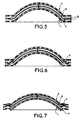
- FIG. 5 shows the operation of the electrostatic loudspeaker according to the present invention.
- Both electrodes 6, 7 and the diaphragm 8 have nearly the same shape.
- the diaphragm 8 is centered between the electrodes 6 and 7.
- the dome shaped diaphragm 8 linearly moves between the first and the second electrode. Due to the enhanced mechanical strength of the diaphragm obtained by the dome shape the main part of the diaphragm within the elastic portion 9 does not change its shape essentially.
- the elastic portion 9 is very flexible in the direction of the center axis of the loudspeaker, i.e. vertical in the figure.
- the main portion and the flexible portion 9 of the diaphragm have different flexibilities in the direction of the center axis although both portions are of the same material.
- the reason for this difference is that the elastic portion 9 is aligned perpendicular to the center access, whereas the portions of the dome have at least components parallel to the center axis.
- FIG. 6 shows a further embodiment of the present invention.
- the elastic portion 9 of the diaphragm 8 is corrugated in the form of one sine wave. Such shape of the elastic portion 9 enhances the flexibility particularly in the direction perpendicular to the center axis of the loudspeaker.
- FIG. 7 shows still another embodiment of the present invention including an elastic portion 9 having the shape of one half of a sine wave.
- This shape also improves the flexibility of the diaphragm 8 so that the parallellity of the movement of the diaphragm with respect to the electrodes 6 and 7 is improved compared to the embodiment of FIG. 5.
- the peripheral portion 11 of each electrode is formed parallel to the elastic portion 9 of the diaphragm 8. Such a form of the peripheral portion 11 serves for preventing touching of the electrode by the diaphragm more effectively.
- the arrow in the figure indicates the amplitude of the vibration movement of the diaphragm 8.
- the corrugation shape of the elastic portion 9 of the diaphragm 8 is described as one sine wave or half of a sine wave.
- the corrugation of the elastic portion 9 may be realized by any other profile like half circular or zigzag.
- this elastic portion enables parallel movement of the dome shaped main portion of the diaphragm 8 so that higher sound pressures and better spatial dispersion can be obtained compared to the prior art.
Landscapes
- Physics & Mathematics (AREA)
- Engineering & Computer Science (AREA)
- Acoustics & Sound (AREA)
- Signal Processing (AREA)
- Electrostatic, Electromagnetic, Magneto- Strictive, And Variable-Resistance Transducers (AREA)
Abstract
In order to enhance the sound pressure of loudspeakers there
is provided an electrostatic acoustic device having a first
electrode (6) for applying an electrical field, a diaphragm
(8) with a main portion, a peripheral portion and an elastic
portion (9) between the main portion and the peripheral portion
and fixing means (10) for fixing the peripheral portion
of the diaphragm (8) to the first electrode(6), wherein the
main portion of the diaphragm (8) is movable by the electrical
field and wherein the elastic portion (9) of the diaphragm
(8) is deformed during movement of the diaphragm (8),
whereas the shape of the main portion of the diaphragm (8) is
essentially maintained, when substantially constant surface
force is applied to the entire surface of the diaphragm (8)
by the electrical field.
Description
- The present invention relates to an electrostatic acoustic device and especially to an electrostatic acoustic device having a first electrode for applying an electrical field, a diaphragm with a main portion, a peripheral portion and an elastic portion between the main portion and the peripheral portion and fixing means for fixing the peripheral portion of the diaphragm to the first electrode, wherein the main portion of the diaphragm is movable by the electrical field.
- Electrostatic acoustic devices in this context primarily include electrostatic loudspeakers or microphones. A typical electrostatic loudspeaker known in the art is shown in FIG. 1. In this type of electrostatic loudspeaker sound pressure can be produced in correspondence with a driving signal by impressing a bias voltage, for instance direct current biasing, with the driving signal. More specifically, as shown in FIG. 1, in a loudspeaker system utilizing an electrostatic speaker, the driving signal 1 output from a power amplifier is boosted several times via a step-
up transformer 2 an output signal of which is output to aspeaker element 5. Thisspeaker element 5 consists ofstationary electrodes stationary electrodes up transformer 2 is impressed between thesestationary electrodes - Furthermore, the
speaker element 5 includes adiaphragm 8 forming the conductive fine filter on the polyester film for example, and maintains thisdiaphragm 8 between thestationary electrodes - The bias voltage of several kV is formed by boosting the commercial power source at a high voltage bias circuit 3 and is applied between a secondary side middle tap of the step up
transformer 2 and thediaphragm 8. The circuit 3 for forming the bias voltage impresses the bias voltage to thediaphragm 8 via resistor 4 having a prescribed resistance value. - With this arrangement, in the loudspeaker system, the driving force F to be expressed by the following equation is generated on the diaphragm.
S - The sound pressure corresponding to the driving signal can be provided by elastically vibrating the diaphragm with this driving force F. Here, ε is the dielectric constant which, in this case, is 8.85 * 10-12 [F/m], S is made up of the electrode area [m2], E0 and E are bias voltage [V] and voltage of driving signal [V] respectively, and d is a distance between the electrodes [m].
- The driving force F expressed by the above equation is produced on the entire diaphragm equally. Since the diaphragm is homogeneous and its outer circumference is fixedly hold, it is deformed to a circular arc shape and elastically vibrated as shown by the arrow in FIG. 2.
- This means that, if the
diaphragm 8 is vibrated with a large amplitude in order to obtain large sound pressure, the deformation of thediaphragm 8 becomes larger accordingly and this also means that the center part of thediaphragm 8 touches thestationary electrodes - Alternatively, spacers may be employed for limiting the diaphragm movement to avoid that the diaphragm touches the stationary electrodes. However, the bass response is limited by such spacers.
- Furthermore, the diaphragm is stretched in a frame and, therefore, is flat essentially. Due to such diaphragm shape, sherical dispersion is poor.
- It is also known that a loudspeaker may have the shape of a portion of a cylinder. The horizontal and vertical profile of such loudspeaker are shown in FIG. 3 again the arrows indicate the movement of the diaphragm. As can be seen immediately the problems discussed above occur similarly.
- Furthermore, DE-A-196 41 503 describes an electrostatic loudspeaker with circular dispersion characteristic. The electrodes and the diaphragm have the shape of a half ball. The periphery of the diaphragm is fixed to a ring by gluing. Thus, the same problems as discussed in connection with FIG. 3 occur.
- In order to enhance the sound pressure US-A-5,471,540 describes an electrostatic loudspeaker having electrodes arranging multiple plate electrodes insulated from each other. The driving signal for each electrode is impressed such that the plate electrodes placed on the outer side have higher voltage. Thus, bigger driving forces are applied to the outer portions of the diaphragm. Since the periphery of the homogeneous diaphragm is fixedly hold by a frame, the peripheral sections of the diaphragm are elastically stretched more than the central sections of the diaphragm. Consequently, the diaphragm can be vibrated in the shape of almost a flat plate, so that the air can be vibrated with larger volume. However, a complicate structure of the electrodes and a complicate driving circuit is necessary to obtain this effect of larger sound pressure.
- In view of the above problems it is the object of the present invention to provide an electrostatic acoustic device enhanced electro-acoustic efficiency, whereby the diaphragm of the device does not touch the electrodes.
- According to the present invention this object is solved by an electrostatic acoustic device having a first electrode for applying an electrical field, a diaphragm with a main portion, a peripheral portion and an elastic portion between the main portion and the peripheral portion and fixing means for fixing the peripheral portion of the diaphragm to the first electrode, wherein the main portion of the diaphragm is movable by the electrical field, and wherein the elastic portion of the diaphragm is deformed during movement of the diaphragm, whereas the shape of the main portion of the diaphragm is essentially maintained, when substantially constant surface force is applied to the entire surface of the diaphragm by the electrical field.
- The elastic portion is deformable easier than other portions of the diaphragm. Thus, if force is applied to the diaphragm, primarily the elastic portion is deformed and the main portion of the diaphragm maintains its shape. In other words, the movement of the diaphragm is very linear, i.e. parallel to the electrodes, compared to the prior art. Consequently a loudspeaker using such technique has a better linear response. Furthermore, high sound pressure level is obtainable since the air volume vibrated by the diaphragm is similar to that of US-A-5,471,540.
- In a preferred embodiment the electrostatic acoustic device further includes a second electrode positioned opposite to the first electrode, wherein the diaphragm is fixed between the first and the second electrode. Additionally, the electrode or the electrodes as well as the diaphragm each may have the shape of a spherical, cylindrical or pyramidal dome. Such shape of the diaphragm would increase the low frequency range and high frequency range for reproduction, since these specific shapes strengthen the diaphragm tremendously. Additionally, thinner or lighter material can be used for the diaphragm compared to the prior art.
- When the shape of the diaphragm is the same like that of the electrodes and the main portion of the diaphragm is moveable parallelly to both electrodes, a larger volume of air can be vibrated by the diaphragm without the risk that the diaphragm touches the electrode. As a result, for providing the same sound pressure level as in the prior art no spacers are needed for preventing a contact between the diaphragm and the electrode inside of a speaker module, for example.
- Further advantages of the dome shape of the diaphragm are the wide spatial dispersion and the easiness of production and handling of such diaphragm.
- Exemplary embodiments of the invention are illustrated in the drawings and are explained in more detail in the following description. In the figures:
- FIG. 1 shows a principal diagram of an electrostatic loudspeaker according to the prior art;
- FIG. 2 is a sectional view of an electrostatic acoustic device according to the prior art showing the diaphragm movement;
- FIG. 3 is a sectional view of another electrostatic loudspeaker of the prior art;
- FIG. 4 is a sectional, perspective and top view to an electrostatic acoustic device according to the present invention;
- FIG. 5 is a sectional view showing the movement of the diaphragm according to the present invention;
- FIG. 6 is a sectional view of another embodiment of the present invention; and
- FIG. 7 is a sectional view of still another embodiment of the present invention.
-
- The present invention will be described in more detail by the preferred embodiment shown in FIG 4.
- FIG. 4 includes a sectional view of an electrostatic loudspeaker on the left side, a perspective view in the middle and a topview of the inventive loudspeaker on the right side. Similar to the prior art loudspeaker of FIG. 2, the inventive loudspeaker of FIG. 4 is built up with a
first electrode 6, asecond electrode 7 and adiaphragm 8 therebetween. Both electrodes are provided with throughholes so that the air vibrated by thediaphragm 8 can pass theelectrodes diaphragm 8 is fixed between theelectrodes means 10. Thus, a parallel structure of theelectrodes diaphragm 8 is obtained. - The fixing means 10 includes two fixing rings which also serve as spacers between the
electrodes diaphragm 8, respectively. Thediaphragm 8 is sandwiched between the two fixing rings. - In this embodiment the fixing means 10 is realized by two identical, electrically insulating rings. However, the fixing means 10 may also include ring sections, pins, bolts or the like. This means that the diaphragm may be fixed on a couple of points of its circumference. The
diaphragm 8 may also include tongues at its periphery for fixing thediaphragm 8 to the fixing means 10. Further, it is possible that the fixing rings shown in FIG. 4 are integrally formed with theelectrodes diaphragm 8 may be clamped between the electrodes, wherein electric insulation is provided by coating theelectrodes diaphragm 8. In other words, the fixing means may be part of one or both of theelectrodes - The main part of the
diaphragm 8 corresponds to a sphere section. At the periphery of the sphere section there is provided a collar. This collar is integral with the sphere section and represents anelastic portion 9. The function of thiselastic portion 9 will be described in connection with FIG. 5, 6 and 7. - The perspective and top views of FIG. 4 show a spherical dome shaped loudspeaker. Such a shaped loudspeaker has an improved spherical dispersion characteristic. In contrast to that loudspeakers with a flat diaphragm have poor spatial dispersion. Similarly, loudspeakers of the one forth cylinder type have good horizontal but bad vertical dispersion.
- The shape of the dome may also be that of a pyramid, cone, ellipsoid, hyperboloid or the like.
- The advantage of the dome shaped
diaphragm 8 is on the one hand that, as already mentioned, the spherical dispersion of the acoustic emission is improved compared to flat or cylindrical loudspeakers. On the other hand the dome shape of thediaphragm 8 improves its mechanical strength. Therefore, the thickness of the diaphragm can be reduced to 0,02 mm or less. Such a thin diaphragm may be realized by a transparent mylar film which is very flexible. Additionally, lighter material for the diaphragm can be employed because of the inherent strength of the dome shape diaphragm. - A further advantage of the dome shaped
diaphragm 8 is that it must not be stretched between the electrodes to be kept centered between them. The dome shaped diaphragm has to be fixed only perpendicular to the surface or the diaphragm by spacers, for example. Thus, no or only very low central forces perpendicular to the moving direction are applied to the dome shapeddiaphragm 8, so that the degree of freedom for choosing the material of the diaphragm is enlarged. - FIG. 5 shows the operation of the electrostatic loudspeaker according to the present invention. Both
electrodes diaphragm 8 have nearly the same shape. Thus, in the zero position of operation thediaphragm 8 is centered between theelectrodes diaphragm 8 linearly moves between the first and the second electrode. Due to the enhanced mechanical strength of the diaphragm obtained by the dome shape the main part of the diaphragm within theelastic portion 9 does not change its shape essentially. Compared to the main portion of thediaphragm 8 theelastic portion 9 is very flexible in the direction of the center axis of the loudspeaker, i.e. vertical in the figure. This means that the main portion and theflexible portion 9 of the diaphragm have different flexibilities in the direction of the center axis although both portions are of the same material. The reason for this difference is that theelastic portion 9 is aligned perpendicular to the center access, whereas the portions of the dome have at least components parallel to the center axis. - As a result the main portion of the
diaphragm 8 having the dome shape vibrates parallel between theelectrodes elastic portion 9 is deformed particularly near the fixing means 10. - FIG. 6 shows a further embodiment of the present invention. The
elastic portion 9 of thediaphragm 8 is corrugated in the form of one sine wave. Such shape of theelastic portion 9 enhances the flexibility particularly in the direction perpendicular to the center axis of the loudspeaker. - FIG. 7 shows still another embodiment of the present invention including an
elastic portion 9 having the shape of one half of a sine wave. This shape also improves the flexibility of thediaphragm 8 so that the parallellity of the movement of the diaphragm with respect to theelectrodes peripheral portion 11 of each electrode is formed parallel to theelastic portion 9 of thediaphragm 8. Such a form of theperipheral portion 11 serves for preventing touching of the electrode by the diaphragm more effectively. As in the preceding figures the arrow in the figure indicates the amplitude of the vibration movement of thediaphragm 8. - The corrugation shape of the
elastic portion 9 of thediaphragm 8 is described as one sine wave or half of a sine wave. However, the corrugation of theelastic portion 9 may be realized by any other profile like half circular or zigzag. In any case this elastic portion enables parallel movement of the dome shaped main portion of thediaphragm 8 so that higher sound pressures and better spatial dispersion can be obtained compared to the prior art. - The above described embodiments show electrostatic loudspeakers employing the present invention. However, the present invention may also be applied to electrostatic microphones or similar transducers.
Claims (9)
- Electrostatic acoustic device havingcharacterized in thata first electrode (6) for applying an electrical field, a diaphragm (8) with a main portion, a peripheral portion and an elastic portion (9) between the main portion and the peripheral portion andfixing means (10) for fixing the peripheral portion of the diaphragm (8) to the first electrode (6), wherein the main portion of the diaphragm (8) is movable by the electrical field,the elastic portion (9) of the diaphragm (8) is deformed during movement of the diaphragm (8), whereas the shape of the main portion of the diaphragm (8) is essentially maintained, when substantially constant surface force is applied to the entire surface of the diaphragm (8) by the electrical field.
- Electrostatic acoustic device according to claim 1, further including a second electrode (7) positioned opposite to the first electrode (6), wherein the diaphragm (8) is fixed with the fixing means (10) between the first and the second electrode.
- Electrostatic acoustic device according to claim 1 or 2, wherein the electrode or electrodes (6, 7) as well as the diaphragm (8) each have the shape of a spherical, cylindrical, pyramidal etc. dome.
- Electrostatic acoustic device according to claim 1, 2 or 3, wherein the profile of the elastic portion (9) of the diaphragm (8) is linear or corrugated, and, preferably, edge portions (11) of the electrode(s) have a corresponding profile.
- Electrostatic acoustic device according to one of the preceding claims, wherein the elastic portion (9) completely or partially surrounds the main portion of the diaphragm.
- Electrostatic acoustic device according to one of the preceding claims, wherein the alignment of the elastic portion (9) of the diaphragm is different from the alignment of a section of the main portion of the diaphragm to which the elastic portion is attached.
- Electrostatic acoustic device according to one of the preceding claims, wherein the thickness of the diaphragm (8) is 0,02 mm or less.
- Electrostatic acoustic device according to one of the preceding claims, wherein the material of the elastic portion (9) is the same like that of the main portion of the diaphragm (8).
- Electrostatic speaker or microphone including an electrostatic acoustic device according to one of the preceding claims.
Priority Applications (3)
| Application Number | Priority Date | Filing Date | Title |
|---|---|---|---|
| EP00402687A EP1194004A1 (en) | 2000-09-29 | 2000-09-29 | Electrostatic acoustic device |
| AU2002212288A AU2002212288A1 (en) | 2000-09-29 | 2001-09-27 | Electrostatic acoustic device |
| PCT/EP2001/011212 WO2002028142A2 (en) | 2000-09-29 | 2001-09-27 | Electrostatic acoustic device |
Applications Claiming Priority (1)
| Application Number | Priority Date | Filing Date | Title |
|---|---|---|---|
| EP00402687A EP1194004A1 (en) | 2000-09-29 | 2000-09-29 | Electrostatic acoustic device |
Publications (1)
| Publication Number | Publication Date |
|---|---|
| EP1194004A1 true EP1194004A1 (en) | 2002-04-03 |
Family
ID=8173886
Family Applications (1)
| Application Number | Title | Priority Date | Filing Date |
|---|---|---|---|
| EP00402687A Withdrawn EP1194004A1 (en) | 2000-09-29 | 2000-09-29 | Electrostatic acoustic device |
Country Status (3)
| Country | Link |
|---|---|
| EP (1) | EP1194004A1 (en) |
| AU (1) | AU2002212288A1 (en) |
| WO (1) | WO2002028142A2 (en) |
Citations (5)
| Publication number | Priority date | Publication date | Assignee | Title |
|---|---|---|---|---|
| US3892927A (en) * | 1973-09-04 | 1975-07-01 | Theodore Lindenberg | Full range electrostatic loudspeaker for audio frequencies |
| EP0616485A1 (en) * | 1993-03-16 | 1994-09-21 | Walter Schmid | Electrostatic transducer |
| US5471540A (en) * | 1992-10-24 | 1995-11-28 | Sony Corporation | Electrostatic loudspeaker having stationary electrodes formed as multiple sheets insulated from each other |
| NL9400923A (en) * | 1994-06-08 | 1996-01-02 | Cornelis Ruijtenberg | Transducer of an electrostatic loudspeaker and method for the production of an insulated stator plate of a transducer of this type |
| DE19641503A1 (en) * | 1996-10-09 | 1998-05-20 | Norman Gerkinsmeyer | Electrostatic loudspeaker with optional circular radiation characteristic |
-
2000
- 2000-09-29 EP EP00402687A patent/EP1194004A1/en not_active Withdrawn
-
2001
- 2001-09-27 WO PCT/EP2001/011212 patent/WO2002028142A2/en not_active Ceased
- 2001-09-27 AU AU2002212288A patent/AU2002212288A1/en not_active Abandoned
Patent Citations (5)
| Publication number | Priority date | Publication date | Assignee | Title |
|---|---|---|---|---|
| US3892927A (en) * | 1973-09-04 | 1975-07-01 | Theodore Lindenberg | Full range electrostatic loudspeaker for audio frequencies |
| US5471540A (en) * | 1992-10-24 | 1995-11-28 | Sony Corporation | Electrostatic loudspeaker having stationary electrodes formed as multiple sheets insulated from each other |
| EP0616485A1 (en) * | 1993-03-16 | 1994-09-21 | Walter Schmid | Electrostatic transducer |
| NL9400923A (en) * | 1994-06-08 | 1996-01-02 | Cornelis Ruijtenberg | Transducer of an electrostatic loudspeaker and method for the production of an insulated stator plate of a transducer of this type |
| DE19641503A1 (en) * | 1996-10-09 | 1998-05-20 | Norman Gerkinsmeyer | Electrostatic loudspeaker with optional circular radiation characteristic |
Also Published As
| Publication number | Publication date |
|---|---|
| WO2002028142A3 (en) | 2002-09-19 |
| AU2002212288A1 (en) | 2002-04-08 |
| WO2002028142A2 (en) | 2002-04-04 |
Similar Documents
| Publication | Publication Date | Title |
|---|---|---|
| US6775388B1 (en) | Ultrasonic transducers | |
| US8107651B2 (en) | Speaker structure | |
| US9667173B1 (en) | Electrostatic parametric transducer and related methods | |
| CN1909747B (en) | Electrostatic ultrasonic transducer, ultrasonic speaker, and electrode manufacturing method | |
| JP5099605B2 (en) | Electronic device and electroacoustic transducer | |
| US8625824B2 (en) | Flat speaker unit and speaker device therewith | |
| US8126171B2 (en) | Electrostatic ultrasonic transducer and ultrasonic speaker | |
| JP4294798B2 (en) | Ultrasonic transducer | |
| KR100574711B1 (en) | Speaker device and sound wave energy propagation method | |
| US4246448A (en) | Electromechanical transducer | |
| CN1997243A (en) | Pliable loudspeaker and its making method | |
| KR100632480B1 (en) | Condenser speaker | |
| US20050244016A1 (en) | Parametric loudspeaker with electro-acoustical diaphragm transducer | |
| CN101656906A (en) | Loudspeaker single body structure | |
| JP2009117888A (en) | Electrostatic speaker | |
| JP2003153395A (en) | Electroacoustic transducer | |
| WO2002028142A2 (en) | Electrostatic acoustic device | |
| KR100739845B1 (en) | Flatbed hybrid speakers | |
| CN103716740A (en) | Loudspeaker device | |
| TWI660637B (en) | Spot sound source speaker | |
| KR200401086Y1 (en) | Flat panel hybrid speaker | |
| JP7099110B2 (en) | Electro-acoustic converter | |
| JP4698320B2 (en) | Condenser microphone unit and condenser microphone | |
| KR200376861Y1 (en) | Condenser type speaker | |
| TWI483623B (en) | Speaker unit |
Legal Events
| Date | Code | Title | Description |
|---|---|---|---|
| PUAI | Public reference made under article 153(3) epc to a published international application that has entered the european phase |
Free format text: ORIGINAL CODE: 0009012 |
|
| AK | Designated contracting states |
Kind code of ref document: A1 Designated state(s): AT BE CH CY DE DK ES FI FR GB GR IE IT LI LU MC NL PT SE |
|
| AX | Request for extension of the european patent |
Free format text: AL;LT;LV;MK;RO;SI |
|
| AKX | Designation fees paid | ||
| REG | Reference to a national code |
Ref country code: DE Ref legal event code: 8566 |
|
| STAA | Information on the status of an ep patent application or granted ep patent |
Free format text: STATUS: THE APPLICATION IS DEEMED TO BE WITHDRAWN |
|
| 18D | Application deemed to be withdrawn |
Effective date: 20021004 |