EP1193996A1 - Procédé de détection de sous-noeuds de commutation pour la commutation de multiplex à répartition de longueur d'onde - Google Patents
Procédé de détection de sous-noeuds de commutation pour la commutation de multiplex à répartition de longueur d'onde Download PDFInfo
- Publication number
- EP1193996A1 EP1193996A1 EP01402417A EP01402417A EP1193996A1 EP 1193996 A1 EP1193996 A1 EP 1193996A1 EP 01402417 A EP01402417 A EP 01402417A EP 01402417 A EP01402417 A EP 01402417A EP 1193996 A1 EP1193996 A1 EP 1193996A1
- Authority
- EP
- European Patent Office
- Prior art keywords
- sub
- granularity
- switching
- node
- subnode
- Prior art date
- Legal status (The legal status is an assumption and is not a legal conclusion. Google has not performed a legal analysis and makes no representation as to the accuracy of the status listed.)
- Granted
Links
- 238000000034 method Methods 0.000 title claims abstract description 44
- 230000003287 optical effect Effects 0.000 claims abstract description 45
- 235000019580 granularity Nutrition 0.000 claims description 146
- 239000000835 fiber Substances 0.000 claims description 89
- 238000013519 translation Methods 0.000 claims description 67
- 238000012795 verification Methods 0.000 claims description 33
- 238000006243 chemical reaction Methods 0.000 claims description 29
- 238000000605 extraction Methods 0.000 claims description 21
- 238000003780 insertion Methods 0.000 claims description 18
- 230000037431 insertion Effects 0.000 claims description 18
- 239000011159 matrix material Substances 0.000 claims description 4
- 230000014616 translation Effects 0.000 description 57
- 238000001514 detection method Methods 0.000 description 50
- 239000013307 optical fiber Substances 0.000 description 6
- 230000005540 biological transmission Effects 0.000 description 5
- 238000010586 diagram Methods 0.000 description 5
- 230000000694 effects Effects 0.000 description 4
- 238000012360 testing method Methods 0.000 description 2
- 238000011282 treatment Methods 0.000 description 2
- 244000236931 Cydonia oblonga Species 0.000 description 1
- 241001080024 Telles Species 0.000 description 1
- 230000003190 augmentative effect Effects 0.000 description 1
- 238000013461 design Methods 0.000 description 1
- 239000010432 diamond Substances 0.000 description 1
- 235000021183 entrée Nutrition 0.000 description 1
- 238000012545 processing Methods 0.000 description 1
Images


Classifications
-
- H—ELECTRICITY
- H04—ELECTRIC COMMUNICATION TECHNIQUE
- H04Q—SELECTING
- H04Q11/00—Selecting arrangements for multiplex systems
- H04Q11/0001—Selecting arrangements for multiplex systems using optical switching
- H04Q11/0005—Switch and router aspects
-
- H—ELECTRICITY
- H04—ELECTRIC COMMUNICATION TECHNIQUE
- H04Q—SELECTING
- H04Q11/00—Selecting arrangements for multiplex systems
- H04Q11/0001—Selecting arrangements for multiplex systems using optical switching
- H04Q11/0062—Network aspects
- H04Q2011/0075—Wavelength grouping or hierarchical aspects
-
- H—ELECTRICITY
- H04—ELECTRIC COMMUNICATION TECHNIQUE
- H04Q—SELECTING
- H04Q11/00—Selecting arrangements for multiplex systems
- H04Q11/0001—Selecting arrangements for multiplex systems using optical switching
- H04Q11/0062—Network aspects
- H04Q2011/0086—Network resource allocation, dimensioning or optimisation
Definitions
- the present invention relates to a method of sub-node detection of an optical switch, for wavelength division multiplex switching.
- Such wavelength division multiplexes are used for data transmission in networks fiber optics.
- the invention applies to the field of transmission networks of the multiplex distribution type wavelengths and equipment of these optical networks such as optical switches.
- optical fibers are not immune to this phenomenon and the amount of data transmitted by optical networks a significantly increased. Indeed, an optical fiber is now planned to transmit more and more wavelengths. We are able to transmit up to 256 wavelengths by optical fiber.
- the switching nodes receive more and more fibers and therefore more and more wavelengths to be switched.
- an optical switch may for example have to switch 100 fibers carrying 160 wavelengths each, each wavelength ensuring a data rate of 10 Gbit / s (10 9 bit / s). This makes a total speed to switch of 160 Tbit / s (10 12 bit / s). The total number of incoming wavelengths is 16000. If you want to switch all the wavelengths individually, you would have to design an optical switch with a very large number of input and output ports, ie 16000 * 16000 ports, which is not achievable with current optical switching matrices. Indeed, due to the very high number of switching points, the electrical control of such matrices would be made too complex.
- the switching of full wavelength multiplexes i.e. fiber switching, strip switching wavelength, and switching wavelengths in the same optical node correspond to commutations of different capacity.
- the planning of distribution multiplex networks wavelength is based on optical switches which present a so-called “multi-granularity” architecture.
- “Granularity” is a concept that relates to predefined sets of transmission resources (typically carrier wavelengths or multiplexes wavelengths), the resources of such a set which can be considered as a whole for some common treatments (typically switching).
- a "multi-granularity" architecture therefore takes into account different levels of granularity to switch traffic total at a switch. For example, part of the total traffic can be switched to the so-called “fiber” level, that is to say, grouping all the wavelengths likely to be carried by an optical fiber, which therefore corresponds to the highest level of granularity. A other part can be switched to length band level wave, which corresponds to a level of granularity intermediate. A final part can be switched to wavelength level, which corresponds to the level of lowest granularity. Intermediate levels of granularity can still be defined.
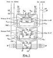
- FIG. 1 presents a diagram of such an optical switching node with a multi-granularity architecture, according to the prior art.
- the multi-granularity architecture we have gone from mono-block switching nodes to switching nodes consisting of a stack of sub-nodes.
- Each switching sub-node is defined by a level of granularity.
- the switching subnode at the fiber granularity level FXC, the switching subnode at the band granularity level BXC, and the switching subnode at the wavelength granularity level WXC are examples of the switching subnode at the fiber granularity level FXC, the switching subnode at the band granularity level BXC, and the switching subnode at the wavelength granularity level WXC.
- the incoming IF fibers are first sent to the IP input ports of the FXC switching subnode.
- some fibers are directly switched to the output fibers OF through the output ports OP of the switching sub-node FXC.
- An AF fiber is directly inserted from the customer on a fiber insertion port P ins of the FXC switching subnode.
- a DF fiber is extracted from a P ext fiber extraction port of the FXC subnode and is sent to the client.
- the DF fiber must be demultiplexed in wavelengths for the client, but the demultiplexers are not shown in the figure.
- F bf fibers are inserted from the switching sub-node BXC on P fiber insertion ports ins of the FXC sub-node. These fibers F bf come from the band-fiber multiplexer Mux B ⁇ F which multiplexes the bands coming from the output ports OP of the switching sub-node BXC. Finally, F fb fibers are extracted from the FXC sub-node through extraction ports and are sent to the IP input ports of the BXC sub-node after demultiplexing the fibers into strips in the demux F-fiber demultiplexer ⁇ B.
- bands B ⁇ b come from the multiplexer Mux ⁇ ⁇ B, which provides band multiplexing of the wavelengths coming from the output ports OP of the switching subnode WXC.
- B bands b ⁇ are extracted from the BXC sub-node through extraction ports and are sent to the IP input ports of the WXC sub-node after demultiplexing the bands in wavelengths in the band-length demultiplexer demux wave B ⁇ ⁇ .
- Wavelengths A ⁇ are directly inserted from the customer on insertion ports P ins of the WXC subnode.
- Wavelengths D ⁇ are extracted through extraction ports of the WXC sub-node and are sent to the client.
- the network is planned without any specification at the nodes. Traffic routing is based on a algorithm which gives the shortest distance path. As for the allocation of resources on the network, it is performed at the wavelength. Although the planning is only based on granularity wavelength, we can observe that in each node of optical switching, a large part of the traffic can be treated at the fiber and tape levels, as if it were a "natural" behavior. At a switching node, the whole multiplex, or only part of the multiplex, comes from the same incoming fiber and goes to the same fiber outgoing. The difficulty is precisely to quantify the different parts of traffic to switch fiber, band and length, respectively wave.
- An object of the present invention is precisely to implement a method for performing a subnode detection in a switching node optical, so that you can know for each node, the traffic going through each subnode and the size of subnodes considered.
- the method according to the invention allows thus optimizing the number of ports required on a node optical switching and thereby optimize costs switching using the widest granularities for switching whenever possible.
- the invention takes as a starting point on which will be implemented the method, the matrix of initial switching of the monoblock node which one seeks to detect subnodes.
- the invention selects for each sub-node, the fibers, length strips wavelength or wavelengths respecting the constraints of switching corresponding to this sub-node.
- the switching constraints are translate in terms of incoming fiber / outgoing fiber and more generally in terms of incoming granularity / granularity outgoing, as well as in terms of length translation wave / band translation.
- the detection process is set implemented through an algorithm defining all the steps necessary for detection.
- the first phase of the process according to the invention involves collecting information from the network how the traffic passes through the initial monoblock node.
- the input parameters of the algorithm implementing the detection method according to the invention are defined.
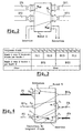
- FIG. 2 is a diagram of a mono-block optical node X which comprises two incoming fibers IF1 and IF2 and two outgoing fibers OF1 and OF2.
- This figure illustrates how the traffic crosses the initial mono-block node and shows an example of the type of information available to the input process.
- the optical path represented in dotted lines comes from the incoming fiber No. 1 IF1 with the last wavelength Wnf of the multiplex, and goes towards the output fiber No. 2 OF2 with the first wavelength W1 of the multiplex .
- the optical path in solid line it is in insertion and it goes to the output fiber No. 2 OF2 with the last wavelength of the Wnf multiplex.
- the second phase of the detection process according to the invention consists in defining the sub-nodes to be sought for their level of granularity and their switching function.
- the complete multiplex includes the twelve lengths ⁇ 1, ⁇ 2, ⁇ 3, ..., ⁇ 12.
- the four bands 1: B11, B12, B13, B14 each include 3 wavelengths. So B11 is composed of the wavelengths ⁇ 1, ⁇ 2 and ⁇ 3; B12 is composed of the wavelengths ⁇ 4, ⁇ 5 and ⁇ 6; B13 is composed wavelengths ⁇ 7, ⁇ 8 and ⁇ 9; and B14 is made up of wavelengths ⁇ 10, ⁇ 11 and ⁇ 12.
- the two bands 2: B21 and B22 each include two strips 1, six lengths wave. Thus, B21 is composed of the six wavelengths ⁇ 1 to ⁇ 6 and B22 is made up of the six wavelengths ⁇ 7 to ⁇ 12.
- Translations can be wavelength translations or tape translations. With a length translation wavelength, any wavelength can be changed in any other wavelength. With a band translation, all wavelengths of a band are translated to the wavelengths of another bandaged. For example, strip B11 from the table in Figure 3 which includes the wavelengths ⁇ 1, ⁇ 2 and ⁇ 3 can be translated to strip B13 which includes the lengths wave ⁇ 7, ⁇ 8 and ⁇ 9.
- optical switching node At an equal level of granularity, we therefore have two blocks of separate switching, one being provided with translation and the other being provided without any translation. So we can consider the optical switching node as a stack of seven blocks.
- Wavelengths can simply be extracted from the fiber or inserted into the fiber, but we always stays in the same fiber.
- the switching process allows traffic to be able to go from one subnode to another, thereby generating internal traffic in the optical switching node.
- the detection method according to the invention imposes a constraint on this internal traffic. This constraint is as follows: no internal traffic can be generated between sub-nodes which have the same level of granularity. The method will not allow, for a subnode considered, to switch part of the multiplex with wavelength translation and the other part of the multiplex without translation. In this case, if a single translation is detected, it will be necessary to switch everything to the sub-node which has the translation function.
- FIG. 4 shows an application of the ricochet verification function of the link with a conversion, based on a wavelength granularity.
- FIG. 4 shows a switching node Z with incoming granularities and outgoing granularities.
- the incoming granularities are composed of two fibers F1 and F2, and a band of wavelengths coming from a node X, B11 X.
- the outgoing granularities are also composed of two fibers FA and FB, and a band of wavelengths which goes towards a node Y, B11 Y.
- the gray diamonds signify an end of connection.
- the wavelengths referenced ⁇ e in the figure are therefore extracted from node Z through extraction ports not shown.
- gray circles they mean that traffic is inserted in the node.
- the wavelengths referenced ⁇ i are therefore inserted into the node Z through insertion ports not shown.
- the half-gray rectangle signifies a link with a wavelength conversion.
- the wavelength ⁇ t therefore undergoes translation.
- the traffic of fiber F1 is not linked with no wavelength conversion, so it could be switched to a WR-OXC sub-node.
- the link with a conversion of the first wavelength ⁇ t of the fiber F2 forces to switch all traffic in a sub-node of the type WT-OXC.
- the example shows us in this specific case, how the verification function works to detect a conversion link with a wavelength.
- the verification function will therefore be recalled for the first wavelength ⁇ 1 of the fiber F1 and for the second wavelength ⁇ 2 of the band B11 X.
- a marking is provided to indicate that a wavelength has already been verified, which avoids redundant tests. This is the case for the first wavelength ⁇ 1 of the fiber F1 which has already been verified.
- the ricochet verification function of the link with a conversion is therefore applied in three stages which repeat in loops.
- a first step first check that none of the wavelengths of a incoming granularity is not related to a translation.
- a second step is to verify that none of the lengths wave of outgoing granularity or granularities corresponding to the incoming granularity is not linked with a translation.
- the incoming granularities and outgoing are said to be corresponding when they have wavelengths in common.
- a third step allows to implement the ricochet effect of the function of verification. This step is to reapply the link verification function with a conversion, for each of the incoming granularities, at all lengths wavelength composing the incoming granularity of the lengths wave making up the outgoing granularity.
- phase a consisting of collecting information about how the traffic passes the initial mono-block node
- phase b consisting in defining the sub-nodes to be sought as for their level of granularity and their switching function.
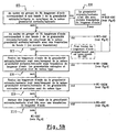
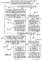
- the sequence of steps E1 to E10, illustrated in FIGS. 5A and 5B, takes place by considering each sub-node successively in an order corresponding to the decrease switching constraints.
- the most switching constraint low corresponds to the lowest level of granularity, either the wavelength, and switching with wavelength translation.
- Detection is therefore done starting from the level of larger granularity towards the level of granularity the lower, first without wavelength translation then with wavelength translation.
- the choice of this order allows for the most complete detection by taking counts all possible subnodes.
- Each of the steps E1 to E10 makes it possible to select, for each subnode considered, all or part of the traffic of an incoming granularity which satisfies the constraints of switching of the considered sub-node.
- a first step E1 is to see if all the wavelengths of the incoming multiplex go towards the same fiber, without wavelength conversion, and see if all wavelengths of the outgoing multiplex come from the same fiber without wavelength conversion. It is necessary imperatively check both directions.
- step E1 When the conditions of step E1 are fulfilled, this means that a fiber granularity level sub-node has been identified.
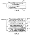
- the output parameters of the detection algorithm will be modified as follows, with reference to FIG. 6 which describes the sub-steps E1-1 and E1-2 of step E1.
- substep E1-1 all the lengths waveform of the considered multiplex will be "marked” as belonging to the F-OXC fiber granularity level sub-node.
- sub-step E1-2 the size of the sub-node F-OXC will be increased by 1, i.e. the number of ports allocated to the F-OXC subnode is going to be incremented by 1.
- step E1 When a multiplex does not meet the criteria for step E1, the same treatment must be applied, but at a lower level of granularity, i.e. the level of band granularity 2.
- a step E2 consists in checking whether at least one group of N2 wavelengths corresponding to a band 2 of the incoming multiplex goes to the same fiber, and if at least one group of N2 wavelengths corresponding to a band 2 of the outgoing multiplex, comes from the same fiber. If step E2 is satisfied, the algorithm must still check in a step E3 if the incoming and outgoing multiplexes are not linked with no wavelength translation. The algorithm will do call to the link ricochet verification function with a conversion to apply it to the incoming multiplex.
- sub-step E3-1 all the wavelengths of the incoming multiplex are "marked” as coming from the B2R-OXC sub-node and all lengths waveform of the outgoing multiplex are marked as going towards the B2R-OXC sub-node.
- marking finds its interest in case of internal traffic in the switching node. Indeed, it gives the possibility to keep track of the passage of the multiplex in the level switching subnode of band granularity 2.
- the detection algorithm allows to deduce that a wavelength of this multiplex is entered in the node at band 2 sub-node. This data has a significant impact on the number of ports because it requires add traffic insertion or extraction ports internal.
- sub-step E3-2 all the wavelengths of the detected band 2 are marked as belonging to the B2R-OXC switching subnode. Also, in substep E3-3, all the other wavelengths of the multiplex also corresponding to band switching 2 are marked as belonging to the switching subnode B2R-OXC. Finally, in substep E3-4, the number of ports input and output of the B2R-OXC switching subnode is increased by the number of bands 2 per fiber.
- a step E4 consists in see if at least one group of N2 wavelengths corresponding to a band 2 of the incoming multiplex goes to the same fiber with a band translation 2, and if this group of N2 wavelengths corresponding to a band 2 of the multiplex outgoing comes from the same fiber with a tape translation 2.
- the B2R-OXC switching subnode If the detection of the B2R-OXC switching subnode is not performed before the detection of the subnode of B2T-OXC switching, the B2R-OXC subnode will never be detected. In this case, so that all the corresponding traffic to band switching 2 is nevertheless taken into account in the B2T-OXC switching sub-node, we add a constraint in step E4 of the detection algorithm.
- This added constraint is shown in parenthesis in block E4 of Figure 5A and consists of looking also if at least one group of N2 wavelengths corresponding to a band 2 of the incoming multiplex goes to the same fiber without any translation, and if this group of N2 wavelengths corresponding to a band 2 of the multiplex outgoing comes from the same fiber without any translation.
- FIG. 5B represents the continuation of the steps of the algorithm concerning the detection of the wavelengths which belong neither to a switching sub-node of the F-OXC type, nor to a switching sub-node of the B2- type OXC.
- the incoming and outgoing granularities can correspond to fiber, band 2 or band 1 traffic of incoming granularity and outgoing granularity in steps of figure 5B in order to keep a notation common at all stages.
- step E5 consists in look if at least one group of N1 wavelengths corresponding to a band 1 of the incoming granularity, ie a fiber or a strip 2, goes towards the same granularity outgoing and if this group of N1 wavelengths corresponding to a band 1 of the outgoing granularity comes of the same incoming granularity. If this condition is satisfied, the algorithm must still check if the incoming granularity is not linked with any conversion of wave length. This verification is carried out at step E6. The algorithm will use the function of ricochet verification of the link with a conversion for apply it to the incoming granularity.
- step E3 In the same way that for the band 2 granularity level in step E3, there it is not necessary to apply this function to the outgoing granularity, the latter being already verified when applying the function to granularity entering.
- the call to the ricochet verification function aims to ensure that the incoming granularity is not related to no wavelength translation before the detect as to be switched in the subnode of band level routing 1.
- sub-step E6-1 consists of mark all wavelengths of the granularity incoming as coming from the B1R-OXC sub-node and to be marked all wavelengths of the outgoing granularity as going to the B1R-OXC sub-node.
- this marking has the function of keeping a trace of the passage of the incoming granularity in the sub-node band granularity level switching 1. So, the detection algorithm makes it possible to deduce that a length wave of this incoming granularity entered the node at band 1 sub-node. This information is important for internal traffic because it takes add the insertion or extraction ports.
- substep E6-2 all lengths waveform of band 1 detected are marked as belonging to the switching subnode B1R-OXC.
- the sub-step E6-3 is to mark all other lengths wave of the incoming granularity also corresponding to a band switching 1 as belonging to the subnode of switching B1R-OXC, and marking all others wavelengths of the corresponding outgoing granularity also at band 1 switching as belonging to the B1R-OXC subnode.
- the increment of inputs of the switching subnode B1R-OXC it is necessary distinguish two cases:
- Sub-step E6-4 distinguishes the case where the granularity incoming is a fiber.
- the number of input ports of the B1R-OXC switch subnode is increased by the number of bands 1 per fiber.
- sub-step E6-4 allows to conclude that the incoming granularity is not a fiber, so the incoming granularity is a band 2.
- the substep E6-4.2 then consists in increasing the number of input ports of the number B1R-OXC switching subnode of bands 1 per band 2.
- the incoming granularity being a band 2
- the sub-step E6-4.3 therefore consists in increasing the number of ports internal B2R / T-OXC subnodes through an extraction port internal to the B1R-OXC sub-node.
- Sub-step E6-5 distinguishes the case where the granularity outgoing is a fiber.
- the output size of the B1R-OXC switching subnode is increased by the number of bands 1 per fiber.
- sub-step E6-5.2 consists in increasing the number of output ports of switching subnode B1R-OXC the number of bands 1 per band 2.
- the outgoing granularity being a band 2 it is also necessary to increase the number of internal ports of the B2R / T-OXC subnode.
- Sub-step E6-5.3 therefore consists of increase the number of internal ports of the B2R / T-OXC sub-node by an internal insertion port coming from the B1R-OXC sub-node.
- step E6 In the event that an incoming granularity does not does not correspond to the constraints of step E5 of the algorithm detection or, if satisfied, the call to the function ricochet verification in step E6 demonstrated a link with a wavelength conversion, the algorithm goes to the next step.
- Step E7 consists in checking whether at least one group of N1 wavelengths corresponding to a band 1 of the incoming granularity goes towards the same outgoing granularity with a tape translation 1, and to see if at least a group of N1 wavelengths corresponding to a band 1 outgoing granularity comes from the same granularity incoming with tape translation 1.
- the B1R-OXC subnode will never be detected. In this case, so that all the corresponding traffic to a band switching 1 is nevertheless taken into account in the switching sub-node B1T-OXC, we add a constraint in step E7 of the detection algorithm.
- This added constraint is shown in parentheses in block E7 of figure 5B and consists in looking also if at least one group of N1 wavelengths corresponding to a band 1 of the incoming granularity going towards the same outgoing granularity without any translation, and if at least one group of N1 wavelengths corresponding to a band 1 of the outgoing granularity comes of the same incoming granularity without any translation.
- Step E8 consists in checking whether all the lengths wave of incoming granularity go to the same outgoing granularity without wavelength translation and if all the wavelengths of the outgoing granularity come from the same incoming granularity without translation of wave length. Step E8 also checks whether the incoming and outgoing granularities are of the same type. This step is planned for the detection of the subnode of WR-OADM switching. In this step, we apply the ricochet verification function of the link with a conversion to ensure that the incoming granularity is not related to no wavelength translation before the detect as to be switched in the subnode of WR-OADM switching.
- sub-step E8-1 consists of mark all wavelengths of the granularity incoming as belonging to the WR-OADM switching subnode and to mark all the wavelengths of the outgoing granularity as belonging to the WR-OADM subnode.
- sub-step E8-2 we check whether the incoming granularity is a fiber. If so, at the substep E8-2.1, the number of input ports of the sub-node WR-OADM is increased by the number of wavelengths per fiber (N), and in substep E8-2.2, all lengths waveform of the incoming multiplex are marked as coming from WR-OADM subnode.
- Sub-step E8-2.3 detects whether the granularity incoming is a strip 2 thanks to the marking of the lengths as coming from B2R / T-0XC. If this is the case, then substep E8-2.4 consists in increasing the number of ports input of the WR-OADM subnode by the number of lengths of wave per band 2, N2. In addition, in step E8-2.5, the number of internal ports of the B2R / T-OXC sub-node is increased by a internal extraction port to the WR-OADM subnode.
- the substep E8-2.6 consists in increasing the number of ports input of the WR-OADM subnode by the number of lengths wave per band 1, N1.
- the number of internal ports of the B1R / T-OXC sub-node will be incremented by an internal extraction port to the WR-OADM sub-node.
- sub-step E8-3 consists in looking if the outgoing granularity is a fiber. If this is the case, sub-step E8-3.1 consists of increase the number of output ports of the WR-OADM subnode by the number of wavelengths per fiber, N. In addition, at sub-step E8-3.2, all the wavelengths of the outgoing multiplex are marked as coming from the sub-node WR-OADM.
- Sub-step E8-3.3 detects whether the granularity outgoing is a strip 2 thanks to the marking of the lengths as going towards B2R / T-OXC.
- the substep E8-3.4 consists in increasing the number of ports of output of the WR-OADM subnode by the number of lengths of wave per band 2, N2.
- the number of internal ports of the B2R / T-OXC subnode is going to be incremented by an internal insert port coming from the sub-node WR-OADM.
- sub-step E8-3.6 consists in increasing the number of output ports of the WR-OADM subnode by the number of wavelengths per band 1, N1.
- the number of internal ports of the B1R / T-OXC sub-node is augmented by an internal insert port from the sub-node WR-OADM.
- step E9 for detection of the WT-OADM switching subnode, consists in checking whether all wavelengths of the incoming granularity go towards the same outgoing granularity and if all the lengths wave of outgoing granularity come from the incoming granularity.
- Step E9 also checks whether the incoming and outgoing granularities are of the same type. Onne not concerned here with whether there are any conversions from wavelengths.
- Step E10 corresponds to the detection of the subnode of lowest granularity level switching, WR / T-OXC.
- This sub-node allows to take into account all the wavelengths that could not be switched to the levels greater granularity.
- the WR / T-OXC sub-node is the last sub-node to be detected in the sequence of algorithm steps, this is the one with the constraints of weakest switching.
- E10 is to check if none of the wavelengths of the incoming granularity is not linked with a conversion of wave length.
- the function of ricochet verification to apply it to the granularity incoming which will thus check for outgoing granularity like before. We do not check if the granularities incoming and outgoing are of the same type.
- a first phase consists in collecting the information about how traffic crosses the initial mono-block node; a second phase consists of define the subnodes to be searched for as to their level of granularity and their switching function; a third phase is to consider each subnode successively in an order corresponding to the decrease switching constraints, i.e. the order given by the sequence of steps E1 to E10; finally a last phase consists in selecting, for each sub-node considered, all or part of the traffic with an incoming granularity which satisfies the switching constraints of the sub-node considered.
- This last phase which is the phase of detection proper, groups all of the steps E1 to E10. These are the conditions set out in each of the steps E1 to E10 who implement this selection phase properly called.
- the last phase of the process is broken down into several sub-phases which provide information usable at the output of the algorithm.
- the information collected makes it possible to give directions on how internal traffic is distributed in the optical switch.
- the algorithm of detection keeps track of traffic flow in this or that subnode of the switch. This result is obtained thanks to the marking of all the granularity traffic incoming, for which all or part of the traffic satisfied the switching constraints of a subnode, as coming of the switching subnode under consideration and the marking of all outgoing granularity traffic like going to the switching subnode considered.
- This sub-phase of marking to keep track of internal traffic is implemented in substeps E3-1, E6-1 and E8-2.2 of detection method which respectively correspond to marking of the wavelengths coming from the B2R / T-OXC sub-node, marking wavelengths from the B1T / T-OXC subnode and marking wavelengths coming from the subnode WR / T-OXC / ADM.
- This result is achieved by marking traffic that meets switching constraints of a subnode considered, such as belonging to this sub-node.
- This marking sub-phase which allows later to distribute traffic in different sub-nodes, is implemented in sub-steps E1-1, E3-2, E3-3, E6-2, E6-3 and E8-1 which correspond respectively to the marking of the wavelengths belonging at the F-OXC sub-node, at the wavelength marking belonging to the B2R / T-OXC sub-node, marking wavelengths belonging to the B1R / T-OXC subnode and the marking of the wavelengths belonging to the WR / T-OXC / ADM subnode.
- the detection algorithm gives the size of each sub-node actually necessary for the switching, i.e. the number of subnode ports. This is achieved by increasing the number of input and output ports as well as the number of ports internal insertion and extraction of a sub-node at each once all or part of the traffic with an incoming granularity satisfies the switching constraints of the sub-node considered.
- This sub-phase which consists in increasing the number of ports of the considered sub-node is carried out at following substeps E1-2, E3-4, E6-4.1 to E6-4.3, E6-5.1 to E6-5.3, E8-2.4 to E8-2.7 and E8-3.4 to E8-3.7 of the algorithm detection.
- the increase in the number of ports is of course related to the incoming and outgoing granularity.
- the detection method according to the invention makes it possible to represent the initial node as a stack of subnodes detected.
Landscapes
- Engineering & Computer Science (AREA)
- Computer Networks & Wireless Communication (AREA)
- Optical Communication System (AREA)
- Data Exchanges In Wide-Area Networks (AREA)
- Use Of Switch Circuits For Exchanges And Methods Of Control Of Multiplex Exchanges (AREA)
- Radio Transmission System (AREA)
- Mobile Radio Communication Systems (AREA)
- Optical Modulation, Optical Deflection, Nonlinear Optics, Optical Demodulation, Optical Logic Elements (AREA)
Abstract
Description
- la figure 1 est un schéma d'un noeud de commutation optique représentant une architecture à multi-granularité selon l'art antérieur, telle que décrite dans le préambule ci-dessus;
- la figure 2 est un schéma d'un noeud optique qui illustre la façon dont le trafic traverse le noeud mono-bloc initial;
- la figure 3 est un tableau récapitulatif des granularités considérées pour la mise en oeuvre du procédé selon l'invention;
- La figure 4 est un schéma illustrant la fonction de vérification par ricochet du lien avec une conversion; et
- les figures 5A, 5B, 6, 7, 8 et 9 illustrent les différentes étapes et sous-étapes du procédé selon l'invention.
- avec quelle longueur d'onde le trafic entre et quitte le noeud,
- si la longueur d'onde est en addition ou en extraction et enfin,
- de quelle fibre vient la longueur d'onde et vers quelle fibre elle va.
- les longueurs d'onde λ1, λ2, λ3, ..., λ12
- les bandes 1 de longueurs d'onde B11, B12, B13, B14
- les bandes 2 de bandes 1 B21, B22, et
- la fibre.
- le sous-noeud de commutation optique de niveau fibre : F-OXC
- le sous-noeud de commutation optique de niveau bande 2 avec une fonction de routage direct, c'est-à-dire sans translation de bande : B2R-OXC
- le sous-noeud de commutation optique de niveau bande 2 avec translation de bande : B2T-OXC
- le sous-noeud de commutation optique de niveau bande 1 avec une fonction de routage direct, c'est-à-dire sans translation de bande : B1R-OXC
- le sous-noeud de commutation optique de niveau bande 1 avec translation de bande : B1T-OXC
- le sous-noeud de commutation optique de niveau longueur d'onde avec fonction de routage direct, c'est-à-dire sans translation de longueur d'onde : WR-OXC
- le sous-noeud de commutation optique de niveau longueur d'onde avec translation de longueur d'onde : WT-OXC
- le sous-noeud correspondant au multiplexeur d'insertion/extraction avec une fonction de routage direct, c'est-à-dire sans translation de longueur d'onde : WR-OADM
- le sous-noeud correspondant au multiplexeur d'insertion/extraction avec translation de longueur d'onde : WT-OADM
- la fonction vérifie qu'aucune longueur d'onde du multiplex rentrant F1 n'est changée;
- la fonction vérifie qu'aucune longueur d'onde du multiplex sortant B11Y n'est changée;
- la fonction est également appliquée à toutes les longueurs d'onde composant le multiplex entrant des longueurs d'onde composant le multiplex sortant, c'est l'effet "ricochet".
- la fonction vérifie qu'aucune longueur d'onde du multiplex entrant B11X n'est changée. A partir de ce multiplex entrant B11X, la fonction va être amenée à tester deux multiplex sortant B11Y et FA, d'où :
- la fonction vérifie qu'aucune longueur d'onde composant le multiplex sortant B11Y n'est changée;
- la fonction vérifie qu'aucune longueur d'onde composant le multiplex sortant FA n'est changée;
- application de l'effet ricochet à partir du premier multiplex sortant pris en considération, B11Y. La fonction de vérification par ricochet est rappelée pour toutes les longueurs d'onde composant le multiplex entrant des longueurs d'onde composant ce multiplex sortant B11Y, soit la première longueur d'onde λ1 de la fibre F1 et la deuxième longueur d'onde λ2 de la bande B11X. Or, grâce au marquage des longueurs d'onde, on sait que ces longueurs d'onde ont déjà été testées. Il est donc inutile de rappeler la fonction de vérification pour ces longueurs d'onde.
- application de l'effet ricochet à partir de l'autre multiplex sortant pris en considération, la fibre FA. La fonction de vérification par ricochet est rappelée pour toutes les longueurs d'onde composant le multiplex entrant des longueurs d'onde composant ce multiplex sortant FA, soit les longueurs d'onde de la fibre F2 et de la bande B11X. Les longueurs d'onde de la bande B11X ont déjà été testées.
- la fonction vérifie qu'aucune longueur d'onde du multiplex entrant F2 n'est changée. Or, il y a une conversion de longueur d'onde. La fonction va détecter cette conversion et le traitement du multiplex entrant F2 est stoppé. On sait alors que le trafic ne pourra pas être commuté dans un sous-noeud de routage du type WR-OXC.
Claims (7)
- Procédé de détection de sous-noeuds de commutation dans un noeud de commutation optique mono-bloc du type multiplex à répartition de longueur d'onde, chaque sous-noeud correspondant à un niveau de granularité donné et à une fonction de commutation donnée, lequel procédé est caractérisé en ce qu'il comprend les phases suivantes consistant à :(a) recueillir des informations concernant la façon dont le trafic traverse le noeud de commutation mono-bloc initial;(b) définir les sous-noeuds devant être recherchés quant à leur niveau de granularité et leur fonction de commutation;(c) considérer chaque sous noeud successivement dans un ordre correspondant à la diminution des contraintes de commutation;(d) sélectionner, pour chaque sous-noeud considéré, tout ou partie du trafic d'une granularité entrante et d'une granularité sortante qui satisfont aux contraintes de commutation du sous-noeud considéré (E1, E2, E3, . . . ., E10);
- Procédé selon la revendication 1, caractérisé en ce que les informations recueillies lors de la phase (a) sont les informations contenues dans la matrice de commutation initiale du noeud monobloc dont on cherche à détecter les sous-noeuds.
- Procédé selon la revendication 1, caractérisé en ce que la phase (b) consiste à rechercher successivement:(b1) le sous-noeud de commutation optique de niveau fibre (F-OXC, E1);(b2) le sous-noeud de commutation optique de niveau bande avec une fonction de routage direct, c'est-à-dire sans translation de bande (B2R-OXC, E2, E3);(b3) le sous-noeud de commutation optique de niveau bande avec translation de bande (B2T-OXC, E4);(b4) le sous-noeud de commutation optique de niveau sous-bande avec une fonction de routage direct, c'est-à-dire sans translation de sous-bande (B1R-OXC, E5, E6);(b5) le sous-noeud de commutation optique de niveau sous-bande avec translation de sous-bande (B1T-OXC, E7);(b6) le sous-noeud de commutation optique de niveau longueur d'onde avec fonction de routage direct, c'est-à-dire sans translation de longueur d'onde (WR-OXC, E10);(b7) le sous-noeud de commutation optique de niveau longueur d'onde avec translation de longueur d'onde (WT-OXC, E10).
- Procédé selon la revendication 3, caractérisé en ce qu'il consiste à rechercher en outre :(b8) le sous-noeud correspondant à un multiplexeur d'insertion/extraction avec une fonction de routage direct, c'est-à-dire sans translation de longueur d'onde (WR-OADM, E8);(b9) le sous-noeud correspondant à un multiplexeur d'insertion/extraction avec translation de longueur d'onde (WT-OADM, E9).
- Procédé selon l'une des revendications 1 à 4, caractérisé en ce que la phase (d) comprend les sous-phases suivantes consistant à :(d1) marquer tout le trafic de la granularité entrante comme venant du sous-noeud considéré et tout le trafic de la granularité sortante comme allant vers le sous-noeud considéré (E3-1, E6-1, E8-2.2);(d2) marquer le trafic qui satisfait aux contraintes de commutation du sous-noeud considéré comme appartenant à ce sous-noeud (E1-1, E3-2, E3-3, E6-2, E6-3, E8-1);(d3) augmenter le nombre de ports du sous-noeud considéré (E1-2, E3-4, E6-4.1 à 3, E6-5.1 à 3, E8-2.4 à 7, E8-3.4 à 7).
- Procédé selon la revendication 3 ou 4, caractérisé en ce que les étapes (b2), (b4), (b6) et (b8) mettent en oeuvre une fonction de vérification par ricochet du lien avec une conversion sur toute granularité entrante susceptible d'être commutée dans un sous-noeud de routage de manière à empêcher tout trafic interne entre des sous-noeuds ayant le même niveau de granularité.
- Procédé selon la revendication 6 caractérisé en ce que la fonction de vérification par ricochet du lien avec une conversion comprend les étapes suivantes se répétant en boucle et consistant à :(i) vérifier qu'aucune des longueurs d'onde de la granularité entrante n'est liée avec une translation;(j) vérifier qu'aucune des longueurs d'onde de la ou des granularités sortantes correspondant à la granularité entrante n'est liée avec une translation;(k) marquer les longueurs d'onde vérifiées de manière à éviter les rebouclages.(l) appliquer de nouveau la fonction de vérification du lien avec une conversion, pour chacune des granularités sortantes, à toutes les longueurs d'onde composant la granularité entrante des longueurs d'onde composant la granularité sortante.
Applications Claiming Priority (2)
| Application Number | Priority Date | Filing Date | Title |
|---|---|---|---|
| FR0012511 | 2000-10-02 | ||
| FR0012511A FR2814903B1 (fr) | 2000-10-02 | 2000-10-02 | Procede de detection de sous-noeuds de commutation pour la commutation de multiplex a repartition de longueur d'onde |
Publications (2)
| Publication Number | Publication Date |
|---|---|
| EP1193996A1 true EP1193996A1 (fr) | 2002-04-03 |
| EP1193996B1 EP1193996B1 (fr) | 2007-11-07 |
Family
ID=8854879
Family Applications (1)
| Application Number | Title | Priority Date | Filing Date |
|---|---|---|---|
| EP01402417A Expired - Lifetime EP1193996B1 (fr) | 2000-10-02 | 2001-09-20 | Procédé de détection de sous-noeuds de commutation pour la commutation de multiplex à répartition de longueur d'onde |
Country Status (6)
| Country | Link |
|---|---|
| US (1) | US7158724B2 (fr) |
| EP (1) | EP1193996B1 (fr) |
| JP (1) | JP2002176393A (fr) |
| AT (1) | ATE377922T1 (fr) |
| DE (1) | DE60131237T2 (fr) |
| FR (1) | FR2814903B1 (fr) |
Cited By (1)
| Publication number | Priority date | Publication date | Assignee | Title |
|---|---|---|---|---|
| EP1401235A1 (fr) * | 2002-09-19 | 2004-03-24 | Alcatel | Brasseur optique d'architecture multigranulaire |
Families Citing this family (2)
| Publication number | Priority date | Publication date | Assignee | Title |
|---|---|---|---|---|
| US20050089027A1 (en) * | 2002-06-18 | 2005-04-28 | Colton John R. | Intelligent optical data switching system |
| FR2860311B1 (fr) * | 2003-09-30 | 2006-06-23 | Cit Alcatel | Methode d'allocation d'au moins une ressource dans un reseau de telecommunications multigranulaire |
Citations (1)
| Publication number | Priority date | Publication date | Assignee | Title |
|---|---|---|---|---|
| EP1030481A1 (fr) * | 1999-01-27 | 2000-08-23 | IMEC vzw | Dispositif de brassage et méthode de commuter, basée sûr commutation spatiale et groupage de canaux |
Family Cites Families (7)
| Publication number | Priority date | Publication date | Assignee | Title |
|---|---|---|---|---|
| JP2928046B2 (ja) * | 1993-04-16 | 1999-07-28 | 日本電気株式会社 | 光ネットワ−ク及びその障害回復方式 |
| US6587240B1 (en) * | 1998-12-21 | 2003-07-01 | Agilent Technologies, Inc. | Optical switching node and method for operating same |
| US6647208B1 (en) * | 1999-03-18 | 2003-11-11 | Massachusetts Institute Of Technology | Hybrid electronic/optical switch system |
| CA2283627C (fr) * | 1999-09-27 | 2008-08-12 | Nortel Networks Corporation | Commutateur de paquets mrl-mrt a grande capacite |
| US7039009B2 (en) * | 2000-01-28 | 2006-05-02 | At&T Corp. | Control of optical connections in an optical network |
| US6882799B1 (en) * | 2000-09-28 | 2005-04-19 | Nortel Networks Limited | Multi-grained network |
| US6999677B2 (en) * | 2000-11-30 | 2006-02-14 | Nortel Networks Limited | Protection switching arrangement for an optical switching system |
-
2000
- 2000-10-02 FR FR0012511A patent/FR2814903B1/fr not_active Expired - Fee Related
-
2001
- 2001-09-20 AT AT01402417T patent/ATE377922T1/de not_active IP Right Cessation
- 2001-09-20 DE DE60131237T patent/DE60131237T2/de not_active Expired - Fee Related
- 2001-09-20 EP EP01402417A patent/EP1193996B1/fr not_active Expired - Lifetime
- 2001-09-27 US US09/963,514 patent/US7158724B2/en not_active Expired - Fee Related
- 2001-09-27 JP JP2001295774A patent/JP2002176393A/ja not_active Withdrawn
Patent Citations (1)
| Publication number | Priority date | Publication date | Assignee | Title |
|---|---|---|---|---|
| EP1030481A1 (fr) * | 1999-01-27 | 2000-08-23 | IMEC vzw | Dispositif de brassage et méthode de commuter, basée sûr commutation spatiale et groupage de canaux |
Non-Patent Citations (3)
| Title |
|---|
| GHANI N: "LAMBDA-LABELING: A FRAMEWORK FOR IP-OVER-WDM USING MPLS", OPTICAL NETWORKS MAGAZINE, SPIE, BELLINGHAM, WA, US, vol. 1, no. 2, April 2000 (2000-04-01), pages 45 - 58, XP000969815, ISSN: 1388-6916 * |
| HOESEL S VAN ET AL: "ROUTING AND MULTIPLEX BUNDLING IN A TRANSMISSION NETWORK", TELETRAFFIC AND DATATRAFFIC IN A PERIOD OF CHANGE. COPENHAGEN, JUNE 19 - 26, 1991, PROCEEDINGS OF THE INTERNATIONAL TELETRAFFIC CONGRESS, AMSTERDAM, NORTH HOLLAND, NL, vol. CONGRESS 13, 19 June 1991 (1991-06-19), pages 401 - 406, XP000303059 * |
| K. HARADA; K. SHIMIZU; T. KUDOU; T. OZEKI: "Hierarchical Optical Path Cross-Connect Systems for Large Scale WDM Networks", IEEE OFC/IOOC'99, 21 February 1999 (1999-02-21) - 26 February 1999 (1999-02-26), pages 356 - 358, XP002175854 * |
Cited By (2)
| Publication number | Priority date | Publication date | Assignee | Title |
|---|---|---|---|---|
| EP1401235A1 (fr) * | 2002-09-19 | 2004-03-24 | Alcatel | Brasseur optique d'architecture multigranulaire |
| FR2844955A1 (fr) * | 2002-09-19 | 2004-03-26 | Cit Alcatel | Brasseur optique d'architecture multigranulaire |
Also Published As
| Publication number | Publication date |
|---|---|
| US7158724B2 (en) | 2007-01-02 |
| US20020039216A1 (en) | 2002-04-04 |
| ATE377922T1 (de) | 2007-11-15 |
| EP1193996B1 (fr) | 2007-11-07 |
| FR2814903B1 (fr) | 2002-12-20 |
| FR2814903A1 (fr) | 2002-04-05 |
| JP2002176393A (ja) | 2002-06-21 |
| DE60131237T2 (de) | 2008-09-04 |
| DE60131237D1 (de) | 2007-12-20 |
Similar Documents
| Publication | Publication Date | Title |
|---|---|---|
| EP0711093B1 (fr) | Système de commutateur pour paquets optiques | |
| FR2735931A1 (fr) | Dispositif reconfigurable pour insertion-extraction de longueurs d'onde | |
| FR2725528A1 (fr) | Ligne a retard optique selectif en longueur d'onde | |
| FR2818059A1 (fr) | Dispositif de demultiplexage de bandes de frequences | |
| WO2011023882A1 (fr) | Representation des degradations physiques dans un reseau de communication optique | |
| EP0838918B1 (fr) | Dispositif d'extraction-insertion de canaux de multiplex de longueurs d'onde | |
| EP1479183B1 (fr) | Procede pour determiner une route spectrale pour une connexion donnee dans un reseau de telecommunication optique | |
| EP1326472B1 (fr) | Noeud de commutation optique à multiplexage à répartition temporelle et répartition sur longueurs d'onde | |
| EP1193996B1 (fr) | Procédé de détection de sous-noeuds de commutation pour la commutation de multiplex à répartition de longueur d'onde | |
| FR2893718A1 (fr) | Dispositif de commutation optique entre des lignes optiques amont et aval, a adjonction de signature de noeud pour le suivi des chemins optiques de connexion | |
| EP1179964A2 (fr) | Commutateur de signaux optiques | |
| EP0697800B1 (fr) | Répartiteur optique | |
| FR2830709A1 (fr) | Dispositif de commutation selective de frequences et circuit a retard optique reconfigurable l'incorporant | |
| FR2814902A1 (fr) | Commutateur pour reseau de transmission optique utilisant le multiplexage en longueur d'onde | |
| FR2736480A1 (fr) | Disposif de coloration de signaux optiques | |
| FR2818065A1 (fr) | Routeur de paquets pour reseau de transmission optique | |
| FR2789538A1 (fr) | Modules de commutation, matrice de commutation comportant de tels modules, et reseau de commutation modulaire non bloquant comportant une telle matrice | |
| FR2818080A1 (fr) | Systeme de demultiplexage/multiplexage en bandes entrelacees | |
| EP1326473B1 (fr) | Dispositif de communication optique et procédé de commande de ce dispositif | |
| EP2606655A1 (fr) | Procede de commutation d'un flot de donnees optiques, produit programme d'ordinateur, moyen de stockage et noeud correspondants | |
| EP0982891B1 (fr) | Dispositif d'insertion/extraction de signaux optiques multiplexés en longueur d'onde | |
| EP1657840B1 (fr) | Réseau de communication (D)WDM à traitement périodique d'un multiplexage spectral | |
| FR2828603A1 (fr) | Systeme de commutation optique tel que brasseur ou routeur pour reseau de transmission | |
| EP1455551A2 (fr) | Module de selection pour commutateur de signaux optiques et commutateur de signaux optiques | |
| FR2935210A1 (fr) | Noeud de commutation de paquets optiques. |
Legal Events
| Date | Code | Title | Description |
|---|---|---|---|
| PUAI | Public reference made under article 153(3) epc to a published international application that has entered the european phase |
Free format text: ORIGINAL CODE: 0009012 |
|
| AK | Designated contracting states |
Kind code of ref document: A1 Designated state(s): AT BE CH CY DE DK ES FI FR GB GR IE IT LI LU MC NL PT SE TR |
|
| AX | Request for extension of the european patent |
Free format text: AL;LT;LV;MK;RO;SI |
|
| 17P | Request for examination filed |
Effective date: 20021004 |
|
| AKX | Designation fees paid |
Free format text: AT BE CH CY DE DK ES FI FR GB GR IE IT LI LU MC NL PT SE TR |
|
| RAP1 | Party data changed (applicant data changed or rights of an application transferred) |
Owner name: ALCATEL LUCENT |
|
| GRAP | Despatch of communication of intention to grant a patent |
Free format text: ORIGINAL CODE: EPIDOSNIGR1 |
|
| GRAS | Grant fee paid |
Free format text: ORIGINAL CODE: EPIDOSNIGR3 |
|
| GRAA | (expected) grant |
Free format text: ORIGINAL CODE: 0009210 |
|
| AK | Designated contracting states |
Kind code of ref document: B1 Designated state(s): AT BE CH CY DE DK ES FI FR GB GR IE IT LI LU MC NL PT SE TR |
|
| REG | Reference to a national code |
Ref country code: GB Ref legal event code: FG4D Free format text: NOT ENGLISH |
|
| REG | Reference to a national code |
Ref country code: IE Ref legal event code: FG4D Free format text: LANGUAGE OF EP DOCUMENT: FRENCH |
|
| REG | Reference to a national code |
Ref country code: CH Ref legal event code: EP |
|
| REF | Corresponds to: |
Ref document number: 60131237 Country of ref document: DE Date of ref document: 20071220 Kind code of ref document: P |
|
| PG25 | Lapsed in a contracting state [announced via postgrant information from national office to epo] |
Ref country code: ES Free format text: LAPSE BECAUSE OF FAILURE TO SUBMIT A TRANSLATION OF THE DESCRIPTION OR TO PAY THE FEE WITHIN THE PRESCRIBED TIME-LIMIT Effective date: 20080218 Ref country code: NL Free format text: LAPSE BECAUSE OF FAILURE TO SUBMIT A TRANSLATION OF THE DESCRIPTION OR TO PAY THE FEE WITHIN THE PRESCRIBED TIME-LIMIT Effective date: 20071107 Ref country code: SE Free format text: LAPSE BECAUSE OF FAILURE TO SUBMIT A TRANSLATION OF THE DESCRIPTION OR TO PAY THE FEE WITHIN THE PRESCRIBED TIME-LIMIT Effective date: 20080207 |
|
| NLV1 | Nl: lapsed or annulled due to failure to fulfill the requirements of art. 29p and 29m of the patents act | ||
| PG25 | Lapsed in a contracting state [announced via postgrant information from national office to epo] |
Ref country code: AT Free format text: LAPSE BECAUSE OF FAILURE TO SUBMIT A TRANSLATION OF THE DESCRIPTION OR TO PAY THE FEE WITHIN THE PRESCRIBED TIME-LIMIT Effective date: 20071107 |
|
| PG25 | Lapsed in a contracting state [announced via postgrant information from national office to epo] |
Ref country code: DK Free format text: LAPSE BECAUSE OF FAILURE TO SUBMIT A TRANSLATION OF THE DESCRIPTION OR TO PAY THE FEE WITHIN THE PRESCRIBED TIME-LIMIT Effective date: 20071107 |
|
| PLBE | No opposition filed within time limit |
Free format text: ORIGINAL CODE: 0009261 |
|
| STAA | Information on the status of an ep patent application or granted ep patent |
Free format text: STATUS: NO OPPOSITION FILED WITHIN TIME LIMIT |
|
| PG25 | Lapsed in a contracting state [announced via postgrant information from national office to epo] |
Ref country code: PT Free format text: LAPSE BECAUSE OF FAILURE TO SUBMIT A TRANSLATION OF THE DESCRIPTION OR TO PAY THE FEE WITHIN THE PRESCRIBED TIME-LIMIT Effective date: 20080407 |
|
| REG | Reference to a national code |
Ref country code: IE Ref legal event code: FD4D |
|
| 26N | No opposition filed |
Effective date: 20080808 |
|
| PG25 | Lapsed in a contracting state [announced via postgrant information from national office to epo] |
Ref country code: IE Free format text: LAPSE BECAUSE OF FAILURE TO SUBMIT A TRANSLATION OF THE DESCRIPTION OR TO PAY THE FEE WITHIN THE PRESCRIBED TIME-LIMIT Effective date: 20071107 |
|
| PGFP | Annual fee paid to national office [announced via postgrant information from national office to epo] |
Ref country code: FR Payment date: 20080912 Year of fee payment: 8 |
|
| PGFP | Annual fee paid to national office [announced via postgrant information from national office to epo] |
Ref country code: GB Payment date: 20080918 Year of fee payment: 8 |
|
| PG25 | Lapsed in a contracting state [announced via postgrant information from national office to epo] |
Ref country code: GR Free format text: LAPSE BECAUSE OF FAILURE TO SUBMIT A TRANSLATION OF THE DESCRIPTION OR TO PAY THE FEE WITHIN THE PRESCRIBED TIME-LIMIT Effective date: 20080208 |
|
| PGFP | Annual fee paid to national office [announced via postgrant information from national office to epo] |
Ref country code: DE Payment date: 20080919 Year of fee payment: 8 |
|
| PG25 | Lapsed in a contracting state [announced via postgrant information from national office to epo] |
Ref country code: FI Free format text: LAPSE BECAUSE OF FAILURE TO SUBMIT A TRANSLATION OF THE DESCRIPTION OR TO PAY THE FEE WITHIN THE PRESCRIBED TIME-LIMIT Effective date: 20071107 |
|
| BERE | Be: lapsed |
Owner name: ALCATEL LUCENT Effective date: 20080930 |
|
| PG25 | Lapsed in a contracting state [announced via postgrant information from national office to epo] |
Ref country code: MC Free format text: LAPSE BECAUSE OF NON-PAYMENT OF DUE FEES Effective date: 20080930 |
|
| REG | Reference to a national code |
Ref country code: CH Ref legal event code: PL |
|
| PG25 | Lapsed in a contracting state [announced via postgrant information from national office to epo] |
Ref country code: BE Free format text: LAPSE BECAUSE OF NON-PAYMENT OF DUE FEES Effective date: 20080930 Ref country code: CY Free format text: LAPSE BECAUSE OF FAILURE TO SUBMIT A TRANSLATION OF THE DESCRIPTION OR TO PAY THE FEE WITHIN THE PRESCRIBED TIME-LIMIT Effective date: 20071107 |
|
| PG25 | Lapsed in a contracting state [announced via postgrant information from national office to epo] |
Ref country code: CH Free format text: LAPSE BECAUSE OF NON-PAYMENT OF DUE FEES Effective date: 20080930 Ref country code: LI Free format text: LAPSE BECAUSE OF NON-PAYMENT OF DUE FEES Effective date: 20080930 |
|
| GBPC | Gb: european patent ceased through non-payment of renewal fee |
Effective date: 20090920 |
|
| REG | Reference to a national code |
Ref country code: FR Ref legal event code: ST Effective date: 20100531 |
|
| PG25 | Lapsed in a contracting state [announced via postgrant information from national office to epo] |
Ref country code: DE Free format text: LAPSE BECAUSE OF NON-PAYMENT OF DUE FEES Effective date: 20100401 Ref country code: FR Free format text: LAPSE BECAUSE OF NON-PAYMENT OF DUE FEES Effective date: 20090930 Ref country code: LU Free format text: LAPSE BECAUSE OF NON-PAYMENT OF DUE FEES Effective date: 20080920 |
|
| PG25 | Lapsed in a contracting state [announced via postgrant information from national office to epo] |
Ref country code: TR Free format text: LAPSE BECAUSE OF FAILURE TO SUBMIT A TRANSLATION OF THE DESCRIPTION OR TO PAY THE FEE WITHIN THE PRESCRIBED TIME-LIMIT Effective date: 20071107 |
|
| PG25 | Lapsed in a contracting state [announced via postgrant information from national office to epo] |
Ref country code: GB Free format text: LAPSE BECAUSE OF NON-PAYMENT OF DUE FEES Effective date: 20090920 |
|
| PG25 | Lapsed in a contracting state [announced via postgrant information from national office to epo] |
Ref country code: IT Free format text: LAPSE BECAUSE OF NON-PAYMENT OF DUE FEES Effective date: 20080930 |
|
| REG | Reference to a national code |
Ref country code: FR Ref legal event code: CA Effective date: 20150521 |
|
| REG | Reference to a national code |
Ref country code: FR Ref legal event code: CA Effective date: 20150521 |