EP1193829A2 - Stator for rotary electromechanical device - Google Patents
Stator for rotary electromechanical device Download PDFInfo
- Publication number
- EP1193829A2 EP1193829A2 EP01120517A EP01120517A EP1193829A2 EP 1193829 A2 EP1193829 A2 EP 1193829A2 EP 01120517 A EP01120517 A EP 01120517A EP 01120517 A EP01120517 A EP 01120517A EP 1193829 A2 EP1193829 A2 EP 1193829A2
- Authority
- EP
- European Patent Office
- Prior art keywords
- coils
- connecting conductors
- stator
- stator core
- disposed
- Prior art date
- Legal status (The legal status is an assumption and is not a legal conclusion. Google has not performed a legal analysis and makes no representation as to the accuracy of the status listed.)
- Granted
Links
Images


Classifications
-
- H—ELECTRICITY
- H02—GENERATION; CONVERSION OR DISTRIBUTION OF ELECTRIC POWER
- H02K—DYNAMO-ELECTRIC MACHINES
- H02K3/00—Details of windings
- H02K3/04—Windings characterised by the conductor shape, form or construction, e.g. with bar conductors
- H02K3/28—Layout of windings or of connections between windings
-
- H—ELECTRICITY
- H02—GENERATION; CONVERSION OR DISTRIBUTION OF ELECTRIC POWER
- H02K—DYNAMO-ELECTRIC MACHINES
- H02K3/00—Details of windings
- H02K3/04—Windings characterised by the conductor shape, form or construction, e.g. with bar conductors
-
- H—ELECTRICITY
- H02—GENERATION; CONVERSION OR DISTRIBUTION OF ELECTRIC POWER
- H02K—DYNAMO-ELECTRIC MACHINES
- H02K3/00—Details of windings
- H02K3/46—Fastening of windings on the stator or rotor structure
- H02K3/52—Fastening salient pole windings or connections thereto
- H02K3/521—Fastening salient pole windings or connections thereto applicable to stators only
- H02K3/522—Fastening salient pole windings or connections thereto applicable to stators only for generally annular cores with salient poles
-
- H—ELECTRICITY
- H02—GENERATION; CONVERSION OR DISTRIBUTION OF ELECTRIC POWER
- H02K—DYNAMO-ELECTRIC MACHINES
- H02K2203/00—Specific aspects not provided for in the other groups of this subclass relating to the windings
- H02K2203/06—Machines characterised by the wiring leads, i.e. conducting wires for connecting the winding terminations
-
- H—ELECTRICITY
- H02—GENERATION; CONVERSION OR DISTRIBUTION OF ELECTRIC POWER
- H02K—DYNAMO-ELECTRIC MACHINES
- H02K2203/00—Specific aspects not provided for in the other groups of this subclass relating to the windings
- H02K2203/12—Machines characterised by the bobbins for supporting the windings
Definitions
- the present invention relates generally to a stator of an inner rotor type rotary electromechanical device and, more particularly, pertains to a wire-connecting structure for electrical connections of coils to the exterior of the device.
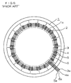
- FIG. 6 is a diagram generally showing the construction of a stator of a conventional rotary electromechanical device disclosed in Japanese Laid-open Patent Publication No. 10-248187.
- designated by the numeral 1 is an annular stator core in which a plurality of magnetic pole teeth 1a projecting radially inward are formed at specific intervals in a circumferential direction
- designated by the numeral 2 are a plurality of coils closely wound around the individual magnetic pole teeth 1a
- designated by the numerals 3, 4 and 5 are first connecting conductors disposed in concentric ringlike form along an axial end face of the stator core 1, joining terminal ends of the coils 2 of each phase (U, V, W) together at one end
- designated by the numeral 6 is a second connecting conductor disposed in ringlike form concentrically with the individual first connecting conductors 3, 4, 5, joining terminal ends of all the coils 2 together at the other end.
- Outlet conductors 3a, 4a, 5a and 6a individually connected to the first and second connecting conductors 3, 4, 5, 6 for establishing electrical connections between the rotary electromechanical device and its exterior extend radially outward as illustrated.
- the coils 2 of the U phase are connected to the first connecting conductor 3 at their one end
- the coils 2 of the V phase are connected to the first connecting conductor 4 at their one end
- the coils 2 of the W phase are connected to the first connecting conductor 5 at their one end, for example, to combine them electrically
- the coils 2 are all connected to the second connecting conductor 6 at their common terminal side and to external equipment via the individual outlet conductors 3a, 4a, 5a, 6a.
- the stator of the conventional rotary electromechanical device is constructed such that the first connecting conductors 3, 4, 5 to which the coils 2 of the individual phases (U, V, W) are connected at one end and the second connecting conductor 6 to which the coils 2 are all connected at the other end are led to the exterior of the device via the respective outlet conductors 3a, 4a, 5a, 6a.
- the outlet conductor 4a runs across the first connecting conductor 3, the outlet conductor 5a runs across the connecting conductors 3 and 4, and the outlet conductor 6a runs across the connecting conductors 3, 4 and 5, and these outlet conductors 4a, 5a, 6a are led to the exterior radially outward.
- This construction has a problem that crossover portions of the outlet conductors 4a, 5a, 6a bulge out in the axial direction of the stator core 1, making it difficult to reduce its thickness.
- the present invention has been made to solve the aforementioned problem of the prior art. Accordingly, it is an object of the invention to provide a stator of a rotary electromechanical device which makes it possible to reduce the stator thickness.
- a stator of a rotary electromechanical device comprises an annular stator core in which a plurality of magnetic pole teeth projecting radially inward are formed at specific intervals in a circumferential direction, a plurality of coils closely wound around the individual magnetic pole teeth with bobbins placed in between, a plurality of first connecting conductors disposed in concentric circular form along an axial end face of the stator core, joining together terminal ends of each group of the coils of the same phase which are connected parallel to one another at one side of the coils, and a second connecting conductor disposed in circular form concentrically with the individual first connecting conductors, joining together terminal ends of all the coils at their opposite side, wherein extreme ends of the first and second connecting conductors are bent into radial directions at specific positions along the circumferential direction of the stator core and led radially outward in a plane perpendicular to the axial direction of the stator core at specific intervals.
- This construction makes it possible to reduce the thickness of the stator of a rotary electromechanical device.
- annular area where the first and second connecting conductors are disposed falls within an annular area where the coils are wound. This enables a further reduction in the thickness of the stator of a rotary electromechanical device.
- the first and second connecting conductors are held by insulating retainer members disposed at specific intervals in the circumferential direction. This enables not only a reduction in the thickness of the stator of a rotary electromechanical device but also an improvement in its reliability.
- the insulating retainer members are fixed to the respective bobbins on which the coils are wound.
- joints between the first and second connecting conductors and the terminal ends of the individual coils are accommodated inside the insulating retainer members. This construction enables a further increase in reliability.
- non-woven fabric is attached to areas of the insulating retainer members where the joints between the first and second connecting conductors and the terminal ends of the individual coils are located. This enables an improvement in insulating performance, not to mention an improvement in reliability.
- the first and second connecting conductors are tied to the respective bobbins by insulating threads.
- FIG. 1 is a plan view generally showing the construction of a stator of a rotary electromechanical device according to the embodiment of the present invention
- FIG. 2 is a wiring diagram showing connections between coils and respective connecting conductors of the stator of the rotary electromechanical device of FIG. 1
- FIG. 3 is an enlarged fragmentary plan view showing the construction of a principal part of the stator of the rotary electromechanical device of FIG. 1
- FIG. 4 is a cross-sectional view taken along lines IV-IV of FIG. 3
- FIG. 5 is an exploded perspective view showing the construction of one each cover 15, insulating retainer member 14 and bobbin 13 shown in FIG. 4. It is to be noted that later-described bobbins 13 and insulating retainer members 14 are not illustrated in FIG. 1.
- each bobbin 13 designated by the numeral 11 is an annular stator core in which a plurality of magnetic pole teeth 11a projecting radially inward are formed at specific intervals in a circumferential direction
- designated by the numeral 12 are a plurality of coils closely wound around the individual magnetic pole teeth 11a with the aforementioned bobbins 13 placed in between
- designated by the numeral 13 is one of the bobbins 13 made of an insulating material, each bobbin 13 including a barrel portion 13a having a U-shaped cross section and a pair of end plates 13b, 13c formed at both ends of the barrel portion 13a as depicted in FIG. 5.
- the bobbins 13 are disposed in pairs in such a manner that each magnetic pole tooth 11a is sandwiched between inner surfaces of the barrel portions 13a of two bobbins 13 located at both ends in the axial direction of the stator.
- the coil 12 is wound around the barrel portions 13a of each bobbin pair 13.
- Designated by the numeral 14 is the aforementioned insulating retainer member which has four grooves 14a formed in a top surface with specific intervals widthwise, grooves 14b and 14c opening upward and downward, respectively, formed at one end by bending operation, and the aforementioned projecting part 14d formed at the opposite end, as shown in FIG. 5.
- the insulating retainer member 14 is locked to the corresponding bobbin 13 by fitting the groove 14c at one end onto the end plate 13b of the bobbin 13 and the projecting part 14d at the other end into the cutout 13e of the end plate 13c.
- Designated by the numeral 15 is the aforementioned cover which is fitted to the top of the insulating retainer member 14, in which a flange 15a for covering the groove 14b of the insulating retainer member 14 is formed at one end of the cover 15 as shown in FIG. 5.
- the insulating retainer member 14 and the cover 15 are attached to each of the bobbins 13 provided at one axial end face of the stator core 11, and later-described first and second connecting conductors 17, 18, 19, 20 are accommodated in the grooves 14a formed in the each insulating retainer member 14. Therefore, an annular area where the first and second connecting conductors 17, 18, 19, 20 are disposed falls within an annular area where the individual coils 12 are wound. This means that the first and second connecting conductors 17, 18, 19, 20 can be run between the end plates 13b, 13c of the individual bobbins 13 so that an increase in physical dimensions in the axial direction of the stator core 11 can be minimized.
- Designated by the numeral 16 are pieces of non-woven fabric which line inside surfaces of both grooves 14a, 14b formed in each insulating retainer member 14, designated by the numerals 17, 18 and 19 are the aforementioned first connecting conductors which are disposed in concentric circular form along the axial end face of the stator core 11 in the annular area where the coils 12 are wound, and designated by the numeral 20 is the aforementioned second connecting conductor disposed concentrically with the first connecting conductors 17, 18, 19 on their outside.
- first and second connecting conductors 17, 18, 19, 20 are retained in the respective grooves 14a formed in the insulating retainer members 14 which are disposed at specific positions along the circumferential direction, the grooves 14a being lined with the non-woven fabric 16, wherein both ends of each of the connecting conductors 17, 18, 19, 20 are bent into radial directions at specific positions along the circumferential direction of the stator core 11 and taken out to the exterior at specific intervals as shown in FIG. 1.
- neither of the connecting conductors 17, 18, 19, 20 is formed into a closed ring, but their extreme ends are led radially outward in a plane perpendicular to the axial direction of the stator core 11 in a manner that they do not overlap one another as shown in FIG. 1.
- the coils 12 are parallel-connected in groups of six to constitute three phases (U, V, W) as shown in FIG. 2, for example.
- the terminal ends of the parallel-connected coils 12 of the U phase are connected to the first connecting conductor 17 at one side
- the terminal ends of the parallel-connected coils 12 of the V phase are connected to the first connecting conductor 18 at one side
- the terminal ends of the parallel-connected coils 12 of the W phase are connected to the first connecting conductor 19 at one side via the respective lead wires 21.
- the terminal ends of all the coils 12 to be joined to a neutral point are connected to the second connecting conductor 20 at the opposite side via the respective lead wires 22.
- the connecting conductors 17, 18, 19, 20 and the lead wires 21, 22 insulated by the non-woven fabric 16 are then accommodated in the grooves 14a, 14b as shown in FIGS. 3 and 4.
- an insulating thread 23 is wound around each assembly of the bobbin pair 13, the insulating retainer member 14 and the cover 15. More specifically, the insulating thread 23 is wound from one end of the assembly to the opposite end over the inside of the barrel portion 13a of each bobbin pair 13 and, folded at the opposite end side, turned back to the starting point of winding over a top surface of the cover 15. The insulating thread 23 is wound around the assembly several times in this fashion to bind the insulating retainer member 14 and the cover 15 to the bobbin pair 13 and to securely hold the connecting conductors 17, 18, 19, 20 and the lead wires 21, 22 in the insulating retainer members 14.
- both ends of each of the first connecting conductors 17, 18, 19 joining together the terminal ends of the parallel-connected coils 12 of the same phase (U, V, W) at one side as well as both ends of the second connecting conductor 20 joining together the terminal ends of all the coils 12 at the opposite side are bent into the radial directions at the specific positions along the circumferential direction of the stator core 11 and led radially outward in the plane perpendicular to the axial direction of the stator core 11 at specific intervals as described above, the four connecting conductors 17, 18, 19, 20 being disposed in concentric circular form.
- the individual connecting conductors 17, 18, 19, 20 do not cross one another, so that they do not bulge out in the axial direction of the stator core 11, making it possible to reduce its thickness.
- first and second connecting conductors 17, 18, 19, 20 are disposed within the annular area where the individual coils 12 are wound, just between the end plates 13b, 13c of the individual bobbins 13, it is possible to prevent the connecting conductors 17, 18, 19, 20 from further bulging out in the axial direction of the stator core 11. Also, since the first and second connecting conductors 17, 18, 19, 20 are accommodated within the insulating retainer members 14, it is possible to hold the connecting conductors 17, 18, 19, 20 in a stably fixed position, and by binding them with the insulating threads 23, it is possible to achieve increased reliability. Furthermore, since the stator core 11 is constructed such that each insulating retainer member 14 can be locked onto its corresponding bobbin 13, the invention serves to improve the efficiency of assembly.
Landscapes
- Engineering & Computer Science (AREA)
- Power Engineering (AREA)
- Insulation, Fastening Of Motor, Generator Windings (AREA)
- Windings For Motors And Generators (AREA)
- Iron Core Of Rotating Electric Machines (AREA)
Abstract
Description
- The present invention relates generally to a stator of an inner rotor type rotary electromechanical device and, more particularly, pertains to a wire-connecting structure for electrical connections of coils to the exterior of the device.
- FIG. 6 is a diagram generally showing the construction of a stator of a conventional rotary electromechanical device disclosed in Japanese Laid-open Patent Publication No. 10-248187.
- In this Figure, designated by the numeral 1 is an annular stator core in which a plurality of
magnetic pole teeth 1a projecting radially inward are formed at specific intervals in a circumferential direction, designated by thenumeral 2 are a plurality of coils closely wound around the individualmagnetic pole teeth 1a, designated by thenumerals coils 2 of each phase (U, V, W) together at one end, and designated by thenumeral 6 is a second connecting conductor disposed in ringlike form concentrically with the individual first connectingconductors coils 2 together at the other end.Outlet conductors conductors - In the conventional rotary electromechanical device whose the stator is constructed as described above, the
coils 2 of the U phase are connected to the first connectingconductor 3 at their one end, thecoils 2 of the V phase are connected to the first connectingconductor 4 at their one end, and thecoils 2 of the W phase are connected to the first connectingconductor 5 at their one end, for example, to combine them electrically, and thecoils 2 are all connected to the second connectingconductor 6 at their common terminal side and to external equipment via theindividual outlet conductors - As stated above, the stator of the conventional rotary electromechanical device is constructed such that the first connecting
conductors coils 2 of the individual phases (U, V, W) are connected at one end and the second connectingconductor 6 to which thecoils 2 are all connected at the other end are led to the exterior of the device via therespective outlet conductors outlet conductor 4a runs across the first connectingconductor 3, theoutlet conductor 5a runs across the connectingconductors outlet conductor 6a runs across the connectingconductors outlet conductors outlet conductors - The present invention has been made to solve the aforementioned problem of the prior art. Accordingly, it is an object of the invention to provide a stator of a rotary electromechanical device which makes it possible to reduce the stator thickness.
- According to a principal feature of the invention, a stator of a rotary electromechanical device comprises an annular stator core in which a plurality of magnetic pole teeth projecting radially inward are formed at specific intervals in a circumferential direction, a plurality of coils closely wound around the individual magnetic pole teeth with bobbins placed in between, a plurality of first connecting conductors disposed in concentric circular form along an axial end face of the stator core, joining together terminal ends of each group of the coils of the same phase which are connected parallel to one another at one side of the coils, and a second connecting conductor disposed in circular form concentrically with the individual first connecting conductors, joining together terminal ends of all the coils at their opposite side, wherein extreme ends of the first and second connecting conductors are bent into radial directions at specific positions along the circumferential direction of the stator core and led radially outward in a plane perpendicular to the axial direction of the stator core at specific intervals.
- This construction makes it possible to reduce the thickness of the stator of a rotary electromechanical device.
- In one aspect of the invention, an annular area where the first and second connecting conductors are disposed falls within an annular area where the coils are wound. This enables a further reduction in the thickness of the stator of a rotary electromechanical device.
- In another aspect of the invention, the first and second connecting conductors are held by insulating retainer members disposed at specific intervals in the circumferential direction. This enables not only a reduction in the thickness of the stator of a rotary electromechanical device but also an improvement in its reliability.
- In still another aspect of the invention, the insulating retainer members are fixed to the respective bobbins on which the coils are wound. This construction makes it possible to provide a stator of a rotary electromechanical device which allows an improvement of the efficiency of assembly, not to mention an improvement in reliability.
- In yet another aspect of the invention, joints between the first and second connecting conductors and the terminal ends of the individual coils are accommodated inside the insulating retainer members. This construction enables a further increase in reliability.
- In a further aspect of the invention, non-woven fabric is attached to areas of the insulating retainer members where the joints between the first and second connecting conductors and the terminal ends of the individual coils are located. This enables an improvement in insulating performance, not to mention an improvement in reliability.
- In a still further aspect of the invention, the first and second connecting conductors are tied to the respective bobbins by insulating threads. This construction makes it possible to achieve a further improvement in reliability, not to mention a reduction in the thickness of the stator.
- These and other objects, features and advantages of the invention will become more apparent upon reading the following detailed description in conjunction with the accompanying drawings.
-
- FIG. 1 is a plan view generally showing the construction of a stator of a rotary electromechanical device according to a preferred embodiment of the present invention;
- FIG. 2 is a wiring diagram showing connections between coils and respective outlet conductors of the stator of the rotary electromechanical device of FIG. 1;
- FIG. 3 is an enlarged fragmentary plan view showing the construction of a principal part of the stator of the rotary electromechanical device of FIG. 1;
- FIG. 4 is a cross-sectional view taken along lines IV-IV of FIG. 3;
- and FIG. 5 is an exploded perspective view showing the construction of a cover, an insulating retainer member and a bobbin shown in FIG. 4; and
- FIG. 6 is a plan view generally showing the construction of a stator of a conventional rotary electromechanical device.
-
- A preferred embodiment of the invention is now described below with reference to the drawings.
- FIG. 1 is a plan view generally showing the construction of a stator of a rotary electromechanical device according to the embodiment of the present invention; FIG. 2 is a wiring diagram showing connections between coils and respective connecting conductors of the stator of the rotary electromechanical device of FIG. 1; FIG. 3 is an enlarged fragmentary plan view showing the construction of a principal part of the stator of the rotary electromechanical device of FIG. 1; FIG. 4 is a cross-sectional view taken along lines IV-IV of FIG. 3; and FIG. 5 is an exploded perspective view showing the construction of one each
cover 15,insulating retainer member 14 andbobbin 13 shown in FIG. 4. It is to be noted that later-describedbobbins 13 andinsulating retainer members 14 are not illustrated in FIG. 1. - In these Figures, designated by the
numeral 11 is an annular stator core in which a plurality ofmagnetic pole teeth 11a projecting radially inward are formed at specific intervals in a circumferential direction, designated by thenumeral 12 are a plurality of coils closely wound around the individualmagnetic pole teeth 11a with theaforementioned bobbins 13 placed in between, and designated by thenumeral 13 is one of thebobbins 13 made of an insulating material, eachbobbin 13 including abarrel portion 13a having a U-shaped cross section and a pair ofend plates barrel portion 13a as depicted in FIG. 5. Thebobbins 13 are disposed in pairs in such a manner that eachmagnetic pole tooth 11a is sandwiched between inner surfaces of thebarrel portions 13a of twobobbins 13 located at both ends in the axial direction of the stator. Thecoil 12 is wound around thebarrel portions 13a of eachbobbin pair 13. There are formedcutouts 13d in theend plate 13b at one end of eachbobbin 13 for passing later-describedlead wires coil 12 while acutout 13e, in which a projectingpart 14d of eachinsulating retainer member 14 is fitted, is formed in theend plate 13c at the other end. - Designated by the
numeral 14 is the aforementioned insulating retainer member which has fourgrooves 14a formed in a top surface with specific intervals widthwise,grooves part 14d formed at the opposite end, as shown in FIG. 5. Theinsulating retainer member 14 is locked to thecorresponding bobbin 13 by fitting thegroove 14c at one end onto theend plate 13b of thebobbin 13 and the projectingpart 14d at the other end into thecutout 13e of theend plate 13c. Designated by thenumeral 15 is the aforementioned cover which is fitted to the top of theinsulating retainer member 14, in which aflange 15a for covering thegroove 14b of theinsulating retainer member 14 is formed at one end of thecover 15 as shown in FIG. 5. - The
insulating retainer member 14 and thecover 15 are attached to each of thebobbins 13 provided at one axial end face of thestator core 11, and later-described first and second connectingconductors grooves 14a formed in the eachinsulating retainer member 14. Therefore, an annular area where the first and second connectingconductors individual coils 12 are wound. This means that the first and second connectingconductors end plates individual bobbins 13 so that an increase in physical dimensions in the axial direction of thestator core 11 can be minimized. - Designated by the
numeral 16 are pieces of non-woven fabric which line inside surfaces of bothgrooves insulating retainer member 14, designated by thenumerals stator core 11 in the annular area where thecoils 12 are wound, and designated by thenumeral 20 is the aforementioned second connecting conductor disposed concentrically with the first connectingconductors conductors respective grooves 14a formed in theinsulating retainer members 14 which are disposed at specific positions along the circumferential direction, thegrooves 14a being lined with thenon-woven fabric 16, wherein both ends of each of the connectingconductors stator core 11 and taken out to the exterior at specific intervals as shown in FIG. 1. - In this arrangement, neither of the connecting
conductors stator core 11 in a manner that they do not overlap one another as shown in FIG. 1. - In this embodiment, the
coils 12 are parallel-connected in groups of six to constitute three phases (U, V, W) as shown in FIG. 2, for example. The terminal ends of the parallel-connectedcoils 12 of the U phase are connected to the first connectingconductor 17 at one side, the terminal ends of the parallel-connectedcoils 12 of the V phase are connected to the first connectingconductor 18 at one side, and the terminal ends of the parallel-connectedcoils 12 of the W phase are connected to the first connectingconductor 19 at one side via therespective lead wires 21. Also, the terminal ends of all thecoils 12 to be joined to a neutral point are connected to the second connectingconductor 20 at the opposite side via therespective lead wires 22. The connectingconductors lead wires non-woven fabric 16 are then accommodated in thegrooves - Finally, after covering the
individual grooves covers 15 to the top of the individualinsulating retainer members 14, aninsulating thread 23 is wound around each assembly of thebobbin pair 13, theinsulating retainer member 14 and thecover 15. More specifically, theinsulating thread 23 is wound from one end of the assembly to the opposite end over the inside of thebarrel portion 13a of eachbobbin pair 13 and, folded at the opposite end side, turned back to the starting point of winding over a top surface of thecover 15. Theinsulating thread 23 is wound around the assembly several times in this fashion to bind theinsulating retainer member 14 and thecover 15 to thebobbin pair 13 and to securely hold the connectingconductors lead wires insulating retainer members 14. - According to the present embodiment, both ends of each of the first connecting
conductors coils 12 of the same phase (U, V, W) at one side as well as both ends of the second connectingconductor 20 joining together the terminal ends of all thecoils 12 at the opposite side are bent into the radial directions at the specific positions along the circumferential direction of thestator core 11 and led radially outward in the plane perpendicular to the axial direction of thestator core 11 at specific intervals as described above, the four connectingconductors conductors stator core 11, making it possible to reduce its thickness. - Since the first and second connecting
conductors individual coils 12 are wound, just between theend plates individual bobbins 13, it is possible to prevent the connectingconductors stator core 11. Also, since the first and second connectingconductors insulating retainer members 14, it is possible to hold the connectingconductors insulating threads 23, it is possible to achieve increased reliability. Furthermore, since thestator core 11 is constructed such that eachinsulating retainer member 14 can be locked onto itscorresponding bobbin 13, the invention serves to improve the efficiency of assembly. - Furthermore, since joints between the first and second connecting
conductors lead wires conductors coils 12, are accommodated inside theinsulating retainer members 14, thelead wires grooves insulating retainer members 14, in which thelead wires fabric 16, so that thenon-woven fabric 16 absorbs liquid resin when it is applied to the aforementioned joints for electrical insulation, and this further improves insulation.
Claims (7)
- A stator for a rotary electromechanical device, comprisingwherein extreme ends of the first and second connecting conductors (17-19; 20) are bent into radial directions at specific positions along the circumferential direction of the stator core (11) and led radially outwardly in a plane perpendicular to the axial direction of the stator core (11) at specific intervals.an annular stator core (11) in which a plurality of magnetic pole teeth (11a) projecting radially inwardly are formed at specific intervals in a circumferential direction;a plurality of coils (12) closely wound around the individual magnetic pole teeth (11a) with bobbins (13) placed in between;a plurality of first connecting conductors (17, 18, 19) disposed in concentric circular form along an axial end face of the stator core (11), joining together terminal ends of each group of the coils (12) of the same phase which are connected parallel to one another at one side of the coils (12); anda second connecting conductor (20) disposed in circular form concentrically with the individual first connecting conductors (17, 18, 19), joining together terminal ends of all the coils (12) at their opposite side;
- The stator according to claim 1,
wherein an annular area where the first and second connecting conductors (17-19; 20) are disposed falls within an annular area where the coils (12) are wound. - The stator according to claim 1 or 2,
wherein the first and second connecting cconductors (17-19; 20) are held by insulating retainer members (14) disposed at specific intervals in the circumferential direction. - The stator according to claim 3,
wherein the insulating retainer members (14) are fixed to the respective bobbins (13) on which the coils (12) are wound. - The stator according to claim 3 or 4,
wherein joints between the first and second connecting conductors (17-19; 20) and the terminal ends of the individual coils (12) are accommodated inside the insulating retainer members (14). - The stator according to claim 5,
wherein non-woven fabric (16) is attached to areas of the insulating retainer members (14) where the joints between the first and second connecting conductors (17-19; 20) and the terminal ends of the individual coils (12) are located. - The stator according to any of claims 1 to 6,
wherein the first and second connecting conductors (17-19; 20) are tied to the respective bobbins (13) by insulating threads (23).
Applications Claiming Priority (2)
| Application Number | Priority Date | Filing Date | Title |
|---|---|---|---|
| JP2000275740A JP3559233B2 (en) | 2000-09-12 | 2000-09-12 | Rotating machine stator |
| JP2000275740 | 2000-09-12 |
Publications (3)
| Publication Number | Publication Date |
|---|---|
| EP1193829A2 true EP1193829A2 (en) | 2002-04-03 |
| EP1193829A3 EP1193829A3 (en) | 2004-09-08 |
| EP1193829B1 EP1193829B1 (en) | 2009-05-27 |
Family
ID=18761315
Family Applications (1)
| Application Number | Title | Priority Date | Filing Date |
|---|---|---|---|
| EP01120517A Expired - Lifetime EP1193829B1 (en) | 2000-09-12 | 2001-08-28 | Stator for rotary electromechanical device |
Country Status (6)
| Country | Link |
|---|---|
| EP (1) | EP1193829B1 (en) |
| JP (1) | JP3559233B2 (en) |
| KR (1) | KR100414624B1 (en) |
| CN (1) | CN1180523C (en) |
| DE (1) | DE60138791D1 (en) |
| TW (1) | TW533654B (en) |
Cited By (16)
| Publication number | Priority date | Publication date | Assignee | Title |
|---|---|---|---|---|
| WO2004114502A1 (en) * | 2003-06-20 | 2004-12-29 | Siemens Aktiengesellschaft | Electric machine comprising a circuit support |
| FR2869472A1 (en) * | 2004-04-21 | 2005-10-28 | Denso Corp | CONCENTRATED WINDING STATOR COIL FOR A ROTATING ELECTRICAL MACHINE |
| FR2869474A1 (en) * | 2004-04-26 | 2005-10-28 | Denso Corp | CONCENTRATED WINDING STATOR COIL FOR A ROTATING ELECTRICAL MACHINE |
| FR2869473A1 (en) * | 2004-04-26 | 2005-10-28 | Denso Corp | CONCENTRATED WINDING STATOR COIL FOR AN ELECTRIC ROTATING MACHINE |
| WO2005096469A3 (en) * | 2004-03-23 | 2005-12-22 | Emerson Electric Co | End cap for interconnecting winding coils of segmented stator |
| WO2005101611A3 (en) * | 2004-03-23 | 2006-01-12 | Emerson Electric Co | End cap for segmented stator |
| WO2006042834A1 (en) * | 2004-10-18 | 2006-04-27 | Siemens Aktiengesellschaft | Electrical machine |
| US7242125B2 (en) | 2004-07-13 | 2007-07-10 | Minebea Co., Ltd. | Device for the insulation of stator slots |
| EP1923981A2 (en) | 2006-11-16 | 2008-05-21 | Fujitsu General Limited | Axail air gap type electric motor |
| EP1713158A4 (en) * | 2004-02-06 | 2012-08-29 | Daikin Ind Ltd | STATOR OF A MOTOR |
| WO2012022563A3 (en) * | 2010-08-17 | 2012-10-26 | Robert Bosch Gmbh | Electrical machine |
| FR3004866A1 (en) * | 2013-04-23 | 2014-10-24 | Valeo Equip Electr Moteur | ELECTRIC MACHINE STATOR WITH INSULATION SLEEVES CONNECTED TO COILS HAVING AN OPTIMIZED LENGTH AND CORRESPONDING ELECTRIC MACHINE |
| US20150123503A1 (en) * | 2012-07-03 | 2015-05-07 | Aisin Aw Co., Ltd. | Stator |
| US20180123433A1 (en) * | 2013-03-29 | 2018-05-03 | Nidec Corporation | Motor and method of manufacturing motor |
| US20240380267A1 (en) * | 2021-08-24 | 2024-11-14 | Meritor Electric Vehicles Germany Gmbh | Dynamoelectric machine as a drive of an electrically driven vehicle |
| WO2025154028A1 (en) * | 2024-01-19 | 2025-07-24 | Tq-Systems Gmbh | Stator for an electric machine, and electric machine |
Families Citing this family (21)
| Publication number | Priority date | Publication date | Assignee | Title |
|---|---|---|---|---|
| JP2003079079A (en) | 2001-09-03 | 2003-03-14 | Honda Motor Co Ltd | Power distribution ring for rotating electric machines |
| DE10327960A1 (en) * | 2003-06-20 | 2005-01-13 | Siemens Ag | Electrical machine with circuit support has start and end of coils fixed to end of stator by at least one circuit carrier and contacted so that definable connections of coils result |
| CN100433505C (en) * | 2004-09-20 | 2008-11-12 | 东洋电装株式会社 | Stator iron core for rotary electric machine |
| JP2006174547A (en) * | 2004-12-14 | 2006-06-29 | Mitsubishi Electric Corp | Rotating electric machine stator |
| JP5041200B2 (en) * | 2006-03-30 | 2012-10-03 | アイシン精機株式会社 | Stator core and its split core |
| JP5111887B2 (en) * | 2007-02-23 | 2013-01-09 | 三菱電機株式会社 | Rotating electric machine stator |
| JP4971025B2 (en) * | 2007-05-02 | 2012-07-11 | 住友電気工業株式会社 | Stator for rotating electrical machine |
| JP4914287B2 (en) * | 2007-05-02 | 2012-04-11 | 住友電気工業株式会社 | Insulator, split stator, and stator for rotating electrical machine |
| JP4914288B2 (en) * | 2007-05-02 | 2012-04-11 | 住友電気工業株式会社 | Bus bar unit |
| JP5109466B2 (en) * | 2007-05-02 | 2012-12-26 | 住友電気工業株式会社 | Stator for rotating electrical machine, bus bar unit used therefor, and connection structure between bus bar terminal and coil terminal |
| JP5334441B2 (en) * | 2008-03-28 | 2013-11-06 | 三洋電機株式会社 | Electric motor |
| JP5150957B2 (en) * | 2008-03-28 | 2013-02-27 | 本田技研工業株式会社 | Rotating electric machine |
| JP5282527B2 (en) * | 2008-10-31 | 2013-09-04 | アイシン精機株式会社 | Motor coil wiring components |
| JP5232618B2 (en) * | 2008-12-16 | 2013-07-10 | 日立オートモティブシステムズ株式会社 | Rotating electric machine |
| JP2013110889A (en) * | 2011-11-22 | 2013-06-06 | Honda Motor Co Ltd | Stator mounting method of rotary electric machine |
| JP5713975B2 (en) * | 2012-09-28 | 2015-05-07 | 三菱電機株式会社 | Electric motor stator, electric motor, hermetic compressor and rotating machine |
| JP6073703B2 (en) * | 2013-02-22 | 2017-02-01 | 住友電装株式会社 | Centralized power distribution member of motor |
| JP5975939B2 (en) * | 2013-06-19 | 2016-08-23 | 三菱電機株式会社 | Rotating electric machine and method of manufacturing rotating electric machine |
| WO2016009523A1 (en) * | 2014-07-17 | 2016-01-21 | 三菱電機株式会社 | Electric motor stator |
| WO2018025375A1 (en) * | 2016-08-04 | 2018-02-08 | 三菱電機株式会社 | Stator for dynamo-electric machine |
| JP2023114692A (en) * | 2022-02-07 | 2023-08-18 | ミネベアミツミ株式会社 | motor stator |
Citations (1)
| Publication number | Priority date | Publication date | Assignee | Title |
|---|---|---|---|---|
| EP0863601A1 (en) | 1997-03-03 | 1998-09-09 | Matsushita Electric Industrial Co., Ltd. | Connection configuration for stator |
Family Cites Families (2)
| Publication number | Priority date | Publication date | Assignee | Title |
|---|---|---|---|---|
| JPS571202A (en) * | 1980-06-04 | 1982-01-06 | Nordson Kk | Electric apparatus to which lead wire is fixed and its manufacture |
| JP4224649B2 (en) * | 1999-01-29 | 2009-02-18 | 株式会社 サーモセッタ | Insulated housing for three-phase AC motor |
-
2000
- 2000-09-12 JP JP2000275740A patent/JP3559233B2/en not_active Expired - Fee Related
-
2001
- 2001-08-03 TW TW090118968A patent/TW533654B/en not_active IP Right Cessation
- 2001-08-28 EP EP01120517A patent/EP1193829B1/en not_active Expired - Lifetime
- 2001-08-28 DE DE60138791T patent/DE60138791D1/en not_active Expired - Lifetime
- 2001-09-11 KR KR10-2001-0055656A patent/KR100414624B1/en not_active Expired - Fee Related
- 2001-09-12 CN CNB011328835A patent/CN1180523C/en not_active Expired - Fee Related
Patent Citations (1)
| Publication number | Priority date | Publication date | Assignee | Title |
|---|---|---|---|---|
| EP0863601A1 (en) | 1997-03-03 | 1998-09-09 | Matsushita Electric Industrial Co., Ltd. | Connection configuration for stator |
Cited By (29)
| Publication number | Priority date | Publication date | Assignee | Title |
|---|---|---|---|---|
| US7692356B2 (en) | 2003-06-20 | 2010-04-06 | Siemens Aktiengesellschaft | Electric machine with a circuit support |
| WO2004114502A1 (en) * | 2003-06-20 | 2004-12-29 | Siemens Aktiengesellschaft | Electric machine comprising a circuit support |
| EP1713158A4 (en) * | 2004-02-06 | 2012-08-29 | Daikin Ind Ltd | STATOR OF A MOTOR |
| US7116023B2 (en) | 2004-03-23 | 2006-10-03 | Emerson Electric Co. | End cap for interconnecting winding coils of a segmented stator to reduce phase-on-phase conditions and associated methods |
| WO2005101611A3 (en) * | 2004-03-23 | 2006-01-12 | Emerson Electric Co | End cap for segmented stator |
| US7586231B2 (en) | 2004-03-23 | 2009-09-08 | Emerson Electric Co. | End cap for segmented stator |
| WO2005096469A3 (en) * | 2004-03-23 | 2005-12-22 | Emerson Electric Co | End cap for interconnecting winding coils of segmented stator |
| US7578047B2 (en) | 2004-03-23 | 2009-08-25 | Emerson Electric Co. | Methods of stitching interconnecting wires on a stator to reduce phase-on-phase conditions |
| US7414347B2 (en) | 2004-03-23 | 2008-08-19 | Emerson Electric Co. | End cap for segmented stator |
| US7382075B2 (en) | 2004-03-23 | 2008-06-03 | Emerson Electric Co. | End cap for segmented stator |
| FR2869472A1 (en) * | 2004-04-21 | 2005-10-28 | Denso Corp | CONCENTRATED WINDING STATOR COIL FOR A ROTATING ELECTRICAL MACHINE |
| US7148593B2 (en) | 2004-04-21 | 2006-12-12 | Denso Corporation | Concentrated winding stator coil for an electric rotary machine |
| FR2869474A1 (en) * | 2004-04-26 | 2005-10-28 | Denso Corp | CONCENTRATED WINDING STATOR COIL FOR A ROTATING ELECTRICAL MACHINE |
| US7262538B2 (en) | 2004-04-26 | 2007-08-28 | Denso Corporation | Concentrated winding stator coil for an electric rotary machine |
| US7126247B2 (en) | 2004-04-26 | 2006-10-24 | Denso Corporation | Concentrated winding stator coil for an electric rotary machine |
| FR2869473A1 (en) * | 2004-04-26 | 2005-10-28 | Denso Corp | CONCENTRATED WINDING STATOR COIL FOR AN ELECTRIC ROTATING MACHINE |
| EP1617543A3 (en) * | 2004-07-13 | 2007-09-05 | Minebea Co., Ltd. | Device for the insulation of stator slots |
| US7242125B2 (en) | 2004-07-13 | 2007-07-10 | Minebea Co., Ltd. | Device for the insulation of stator slots |
| DE102004050646A1 (en) * | 2004-10-18 | 2006-05-04 | Siemens Ag | Electric machine |
| WO2006042834A1 (en) * | 2004-10-18 | 2006-04-27 | Siemens Aktiengesellschaft | Electrical machine |
| EP1923981A3 (en) * | 2006-11-16 | 2009-07-15 | Fujitsu General Limited | Axail air gap type electric motor |
| EP1923981A2 (en) | 2006-11-16 | 2008-05-21 | Fujitsu General Limited | Axail air gap type electric motor |
| WO2012022563A3 (en) * | 2010-08-17 | 2012-10-26 | Robert Bosch Gmbh | Electrical machine |
| US20150123503A1 (en) * | 2012-07-03 | 2015-05-07 | Aisin Aw Co., Ltd. | Stator |
| US20180123433A1 (en) * | 2013-03-29 | 2018-05-03 | Nidec Corporation | Motor and method of manufacturing motor |
| FR3004866A1 (en) * | 2013-04-23 | 2014-10-24 | Valeo Equip Electr Moteur | ELECTRIC MACHINE STATOR WITH INSULATION SLEEVES CONNECTED TO COILS HAVING AN OPTIMIZED LENGTH AND CORRESPONDING ELECTRIC MACHINE |
| WO2014174201A3 (en) * | 2013-04-23 | 2015-08-06 | Valeo Equipements Electriques Moteur | Electrical machine stator provided with insulating sheets of optimized length of wires connected to the coils, and corresponding electrical machine |
| US20240380267A1 (en) * | 2021-08-24 | 2024-11-14 | Meritor Electric Vehicles Germany Gmbh | Dynamoelectric machine as a drive of an electrically driven vehicle |
| WO2025154028A1 (en) * | 2024-01-19 | 2025-07-24 | Tq-Systems Gmbh | Stator for an electric machine, and electric machine |
Also Published As
| Publication number | Publication date |
|---|---|
| KR20020021021A (en) | 2002-03-18 |
| EP1193829B1 (en) | 2009-05-27 |
| CN1344054A (en) | 2002-04-10 |
| TW533654B (en) | 2003-05-21 |
| DE60138791D1 (en) | 2009-07-09 |
| CN1180523C (en) | 2004-12-15 |
| KR100414624B1 (en) | 2004-01-13 |
| JP3559233B2 (en) | 2004-08-25 |
| EP1193829A3 (en) | 2004-09-08 |
| JP2002095199A (en) | 2002-03-29 |
Similar Documents
| Publication | Publication Date | Title |
|---|---|---|
| EP1193829A2 (en) | Stator for rotary electromechanical device | |
| JP6068625B2 (en) | Segmented stator assembly | |
| CN100442640C (en) | electric motor | |
| US9502940B2 (en) | Connection terminal, connection terminal unit, and motor | |
| US20090146523A1 (en) | Stator for rotary electric machine, and rotary electric machine using the stator | |
| US9837869B2 (en) | Stator with bus bar portion embedded between adjacent lane change portions and connected to terminal portion | |
| US20170093239A1 (en) | Rotary electric machine | |
| US7923885B2 (en) | Stator for rotary electric machine, and rotary electric machine using the stator | |
| JPH10248187A (en) | Stator connection structure | |
| CN103427525B (en) | With insulating component that stator module is used together and the method for assembling the stator module | |
| JP6044382B2 (en) | Multi-gap rotating electric machine | |
| JP7639462B2 (en) | Motor | |
| US7026735B2 (en) | Stator of rotating electric machine | |
| JP7362794B2 (en) | Motor stator and motor | |
| JP2010068590A (en) | Stator | |
| CN105931815A (en) | Planar transformer | |
| JP2001275291A (en) | Motor stator | |
| CN114342223B (en) | Stator | |
| JP2015133809A (en) | Method of manufacturing stator | |
| JP3093396B2 (en) | Induction motor stator | |
| JP4826736B2 (en) | Armature | |
| JPH10285841A (en) | Rotating electric machine stator | |
| JPH09219959A (en) | Electric motor stator | |
| JP7632475B2 (en) | Stator assembly | |
| US20240097539A1 (en) | Method for forming a stator winding, sheet-metal stator, and electric motor |
Legal Events
| Date | Code | Title | Description |
|---|---|---|---|
| PUAI | Public reference made under article 153(3) epc to a published international application that has entered the european phase |
Free format text: ORIGINAL CODE: 0009012 |
|
| AK | Designated contracting states |
Kind code of ref document: A2 Designated state(s): AT BE CH CY DE DK ES FI FR GB GR IE IT LI LU MC NL PT SE TR |
|
| AX | Request for extension of the european patent |
Free format text: AL;LT;LV;MK;RO;SI |
|
| PUAL | Search report despatched |
Free format text: ORIGINAL CODE: 0009013 |
|
| AK | Designated contracting states |
Kind code of ref document: A3 Designated state(s): AT BE CH CY DE DK ES FI FR GB GR IE IT LI LU MC NL PT SE TR |
|
| AX | Request for extension of the european patent |
Extension state: AL LT LV MK RO SI |
|
| 17P | Request for examination filed |
Effective date: 20041005 |
|
| AKX | Designation fees paid |
Designated state(s): DE FR GB NL |
|
| RAP1 | Party data changed (applicant data changed or rights of an application transferred) |
Owner name: MITSUBISHI DENKI KABUSHIKI KAISHA |
|
| GRAP | Despatch of communication of intention to grant a patent |
Free format text: ORIGINAL CODE: EPIDOSNIGR1 |
|
| GRAS | Grant fee paid |
Free format text: ORIGINAL CODE: EPIDOSNIGR3 |
|
| GRAA | (expected) grant |
Free format text: ORIGINAL CODE: 0009210 |
|
| AK | Designated contracting states |
Kind code of ref document: B1 Designated state(s): DE FR GB NL |
|
| REG | Reference to a national code |
Ref country code: GB Ref legal event code: FG4D |
|
| REF | Corresponds to: |
Ref document number: 60138791 Country of ref document: DE Date of ref document: 20090709 Kind code of ref document: P |
|
| REG | Reference to a national code |
Ref country code: GB Ref legal event code: S27 Free format text: APPLICATION FILED; APPLICATION TO AMEND SPECIFICATION UNDER SECTION 27 FILED ON 7 AUGUST 2009 |
|
| REG | Reference to a national code |
Ref country code: GB Ref legal event code: S27 Free format text: APPLICATION OPEN FOR OPPOSITION |
|
| PLBE | No opposition filed within time limit |
Free format text: ORIGINAL CODE: 0009261 |
|
| STAA | Information on the status of an ep patent application or granted ep patent |
Free format text: STATUS: NO OPPOSITION FILED WITHIN TIME LIMIT |
|
| 26N | No opposition filed |
Effective date: 20100302 |
|
| REG | Reference to a national code |
Ref country code: GB Ref legal event code: S27 Free format text: SPECIFICATION AMENDED; APPLICATION FOR AMENDMENT UNDER SECTION 27 FILED ON 7 AUGUST 2009, ALLOWED ON 9 JUNE 2010 |
|
| PGFP | Annual fee paid to national office [announced via postgrant information from national office to epo] |
Ref country code: NL Payment date: 20100825 Year of fee payment: 10 |
|
| PGFP | Annual fee paid to national office [announced via postgrant information from national office to epo] |
Ref country code: FR Payment date: 20100909 Year of fee payment: 10 |
|
| PGFP | Annual fee paid to national office [announced via postgrant information from national office to epo] |
Ref country code: GB Payment date: 20100831 Year of fee payment: 10 |
|
| REG | Reference to a national code |
Ref country code: GB Ref legal event code: 746 Effective date: 20110513 |
|
| REG | Reference to a national code |
Ref country code: DE Ref legal event code: R084 Ref document number: 60138791 Country of ref document: DE Effective date: 20110627 Ref country code: DE Ref legal event code: R084 Ref document number: 60138791 Country of ref document: DE Effective date: 20110506 |
|
| REG | Reference to a national code |
Ref country code: NL Ref legal event code: V1 Effective date: 20120301 |
|
| GBPC | Gb: european patent ceased through non-payment of renewal fee |
Effective date: 20110828 |
|
| REG | Reference to a national code |
Ref country code: FR Ref legal event code: ST Effective date: 20120430 |
|
| PG25 | Lapsed in a contracting state [announced via postgrant information from national office to epo] |
Ref country code: NL Free format text: LAPSE BECAUSE OF NON-PAYMENT OF DUE FEES Effective date: 20120301 |
|
| PG25 | Lapsed in a contracting state [announced via postgrant information from national office to epo] |
Ref country code: GB Free format text: LAPSE BECAUSE OF NON-PAYMENT OF DUE FEES Effective date: 20110828 Ref country code: FR Free format text: LAPSE BECAUSE OF NON-PAYMENT OF DUE FEES Effective date: 20110831 |
|
| PGFP | Annual fee paid to national office [announced via postgrant information from national office to epo] |
Ref country code: DE Payment date: 20140821 Year of fee payment: 14 |
|
| REG | Reference to a national code |
Ref country code: DE Ref legal event code: R119 Ref document number: 60138791 Country of ref document: DE |
|
| PG25 | Lapsed in a contracting state [announced via postgrant information from national office to epo] |
Ref country code: DE Free format text: LAPSE BECAUSE OF NON-PAYMENT OF DUE FEES Effective date: 20160301 |