EP1193776A2 - Deformable micro-actuator - Google Patents
Deformable micro-actuator Download PDFInfo
- Publication number
- EP1193776A2 EP1193776A2 EP01203553A EP01203553A EP1193776A2 EP 1193776 A2 EP1193776 A2 EP 1193776A2 EP 01203553 A EP01203553 A EP 01203553A EP 01203553 A EP01203553 A EP 01203553A EP 1193776 A2 EP1193776 A2 EP 1193776A2
- Authority
- EP
- European Patent Office
- Prior art keywords
- actuator
- micro
- elastomer material
- metallic layers
- set forth
- Prior art date
- Legal status (The legal status is an assumption and is not a legal conclusion. Google has not performed a legal analysis and makes no representation as to the accuracy of the status listed.)
- Withdrawn
Links
Images
Classifications
-
- H—ELECTRICITY
- H02—GENERATION; CONVERSION OR DISTRIBUTION OF ELECTRIC POWER
- H02N—ELECTRIC MACHINES NOT OTHERWISE PROVIDED FOR
- H02N1/00—Electrostatic generators or motors using a solid moving electrostatic charge carrier
- H02N1/002—Electrostatic motors
- H02N1/006—Electrostatic motors of the gap-closing type
Definitions
- This invention relates to micro-actuators usable to produce controlled movements.
- U.S. Patent No. 2,896,507 describes an imaging member which includes an elastically deformable layer sandwiched between a pair of electrode plates. In operation, an electrical field is established across the deformable layer, thus causing this layer to deform. The deformation produces relative movement between the electrode plates.
- U.S. Patent No. 3,716,359 discloses improved thin flexible metallic layer electrode plates comprising a plurality of different metals such as, for example, gold, indium, aluminum, silver, magnesium, copper, cobalt, iron, chromium, nickel, gallium, cadmium, mercury, and lead. Various techniques for forming the metallic layers on the elastomer layer are described including, for example, by vacuum evaporation.
- U.S. Patent No. 4,163,667 describes the use of a composition of titanium and silver for use as the flexible conductive metallic layer electrode plates in imaging members.
- a micro-actuator has a pair of conductive metallic layers connectable to an electrical potential source so as to induce a force between the metallic layers upon application of an electrical field.
- a layer of dense elastomer material is sandwiched between the pair of conductive metallic layers such that there will be a change in the volume of the elastomer material in response to relative movement between the conductive metallic layers.
- the elastomer material has at least one void within the elastomer material, whereby the micro-actuator exhibits void-enhanced growth and reduction in size in response to the effected force induced by the applied electrical field.
- At least one of the metallic layers is a flexible electrode plate.
- the other metallic layer may be rigid and essentially non-deformable.
- the elastomer material has substantial plurality of voids.
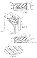
- FIG. 2 is a perspective view of the micro-actuator of FIG. 1 with portions of the figure cut away for clarity.
- Micro-actuator 10 includes an optional support substrate 12, a thin, flexible conductive layer first electrode plate 14, and an optional layer of insulating material 16. Insulating material 16, in turn, carries a deformable elastomer layer 18.
- Overlying elastomer layer 18 is a rigid, essentially non-deformable conductive metallic second electrode plate 20.
- First and second electrode plates 14 and 20, respectively, are connected to an electrical potential source 22 by leads 24.
- Potential source 22 may be A.C., D.C., or a combination thereof.
- the potential source may also include suitable switching apparatus, not shown.
- Conductive layer first electrode plate 14 may be formed as a rigid, essentially non-deformable conductive metallic plate, eliminating the need for support substrate 12.
- second electrode plate 20 may be formed as a thin, flexible conductive layer on a support substrate, not shown.
- a micro-actuator 10' incorporates insulating material in a deformable elastomer layer 18'.
- an electric field is established across deformable elastomer layer 18 (FIGS. 1 and 2) or 18' (FIG. 3) in a direction normal the planes of first and second electrode plates 14 and 20 by applying a potential from source 22 to the electrode plates.
- the mechanical force of attraction between first and second electrode plates 14 and 20 due to the electric field causes deformable elastomer layer to compress.
- first and second electrode plates 14 and 20 will repulse and cause the elastomer layer to deform in expansion if like electrical poles are applied to electrode plates 14 and 20.
- Deformable elastomer layer 18 may comprise any suitable elastomer material, such as for example natural rubber or synthetic polymers with rubber-like characteristics (silicone rubber, styrenebutadiene, polybutadiene, neoprene, butyl, polyisoprene, nitrile, urethane, and ethylene rubbers). Elastomers having relatively high dielectric strength will allow the devices to be operated at higher voltage levels, which in many instances may be preferred.
- Suitable selection of a particular elastomer material which exhibits an elastic modulus appropriate for a predetermined intended use is within ordinary skill given the description herein. For example, a relatively more stiff elastomer will typically recover more rapidly when an electric field is removed. On the other hand, an elastomer material having a relatively low elastic modulus is typically capable of greater deformations for a given value of electric field.
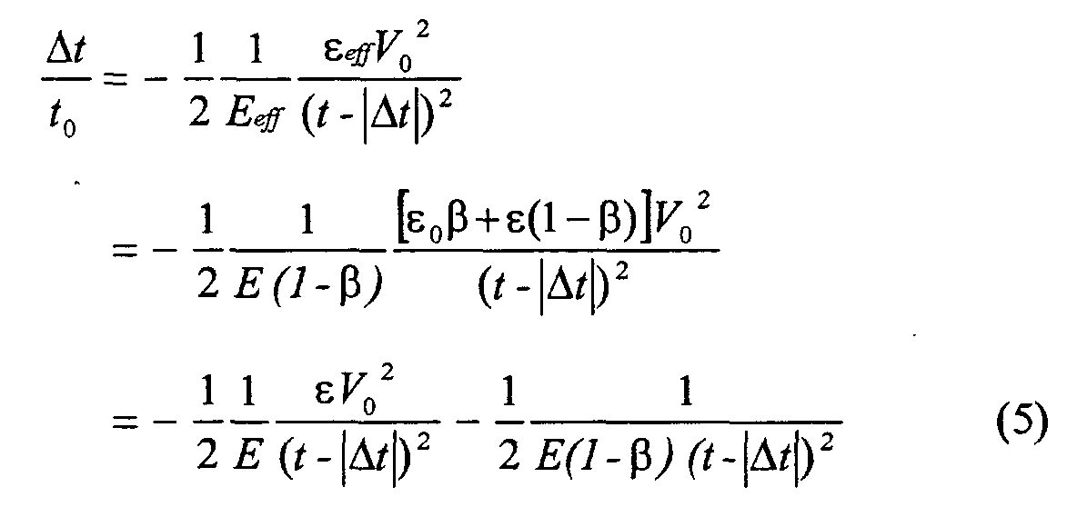
- the voids give rise to effective values for the Young's modulus E eff and permittivity ⁇ eff of deformable elastomer layer 18 or 18'. To first order, these effective values are obtained via a simple volumetric weighting of the respective values of the void and the portion of fully dense solid elastomer.
- E and ⁇ are the Young's modulus and the permittivity of the solid elastomer, respectively
- ⁇ ⁇ V void V tot
- ⁇ V void is the volume occupied by the voids
- V tot is the total volume occupied by deformable elastomer layer 18 or 18' in its undeformed state.
- ⁇ V void is limited to approximately 25% of the total volume. Therefore, 0 ⁇ ⁇ ⁇ 0.25.
- the strain is negative indicating a compressive deformation.
- the first term in equation (5) is the strain due to a fully dense solid elastomer (without voids).
- the thickness t 0 of deformable elastomer layer 18 or 18' should be much smaller that either of the side dimensions of the area A of electrode plate 14.
- the thickness t 0 should be less than 10 ⁇ m.
- the thickness of deformable elastomer layer 18 or 18' may be in the range of from about 0.5 microns to about 200 microns, depending upon the dielectric properties of the elastomer.
- Electrode plate 20 should have good lateral conductivity, excellent stability, and little internal stress; as well as being highly adherent to deformable elastomer layer 18 or 18'. Suitable materials for electrode plate 20 include gold, silver, chromium, nickel, aluminum, conducting polymer, etc. Electrode plate 20 may be formed such as by chemical reaction, precipitation from a solution, electrophoresis, electrolysis, electroless plating, vapor deposition and others. The thickness of electrode plate 20 may, for example, be in the range of from about 200 angstroms to about 5,000 angstroms depending upon any desired flexibility, and the requisite strength and conductivity.
- the number of voids, the size of the individual voids, and the total volume of the voids relative to the volume of elastically deformable elastomer layer 18 are variables selectable during the design of a particular system.
Landscapes
- Micromachines (AREA)
- Laminated Bodies (AREA)
Abstract
Description
Claims (10)
- A micro-actuator comprising:a pair of conductive metallic layers connectable to an electrical potential source so as to induce a force between the metallic layers upon application of an electrical field; anda layer of dense elastomer material sandwiched between the pair of conductive metallic layers such that there will be a change in the volume of the elastomer material in response to relative movement between the conductive metallic layers, said dense elastomer material having at least one void within the elastomer material, whereby the micro-actuator exhibits void-enhanced growth and reduction in size in response to the effected force induced by the applied electrical field.
- A micro-actuator as set forth in Claim 1, wherein at least one of the metallic layers is a flexible electrode plate.
- A micro-actuator as set forth in Claim 2, wherein the other of the metallic layers is rigid and essentially non-deformable.
- A micro-actuator as set forth in Claim 1, wherein said elastomer material has substantial plurality of voids.
- A micro-actuator as set forth in Claim 1, further comprising a support layer integral with one of the conductive metallic layers to inhibit movement of said one conductive metallic layer upon inducement of the force between the metallic layers.
- A micro-actuator as set forth in Claim 1, wherein said elastomer material is electrically conductive, and further comprising a layer of electrically insulating material between at least on of the electrode plates and the elastomer material.
- A micro-actuator as set forth in Claim 1, wherein said elastomer material is a dielectric.
- A micro-actuator as set forth in Claim 1, wherein said elastomer material is natural rubber.
- A micro-actuator as set forth in Claim 1, wherein said elastomer material is synthetic polymer.
- A micro-actuator as set forth in Claim 1, wherein a total volume occupied by the voids is limited to approximately 25% of a total volume occupied by the layer of dense elastomer material.
Applications Claiming Priority (2)
| Application Number | Priority Date | Filing Date | Title |
|---|---|---|---|
| US671438 | 2000-09-27 | ||
| US09/671,438 US6477029B1 (en) | 2000-09-27 | 2000-09-27 | Deformable micro-actuator |
Publications (2)
| Publication Number | Publication Date |
|---|---|
| EP1193776A2 true EP1193776A2 (en) | 2002-04-03 |
| EP1193776A3 EP1193776A3 (en) | 2005-05-18 |
Family
ID=24694505
Family Applications (1)
| Application Number | Title | Priority Date | Filing Date |
|---|---|---|---|
| EP01203553A Withdrawn EP1193776A3 (en) | 2000-09-27 | 2001-09-19 | Deformable micro-actuator |
Country Status (2)
| Country | Link |
|---|---|
| US (1) | US6477029B1 (en) |
| EP (1) | EP1193776A3 (en) |
Cited By (1)
| Publication number | Priority date | Publication date | Assignee | Title |
|---|---|---|---|---|
| NL2003681C2 (en) * | 2009-10-21 | 2011-04-26 | Stichting Materials Innovation Inst M2I | Micro electromechanical switch and method of manufacturing such a micro electromechanical switch. |
Families Citing this family (5)
| Publication number | Priority date | Publication date | Assignee | Title |
|---|---|---|---|---|
| KR100425776B1 (en) * | 2002-04-23 | 2004-04-01 | 전자부품연구원 | Micro actuator |
| US8704423B2 (en) * | 2008-08-22 | 2014-04-22 | The United States Of America As Represented By The Administrator Of The National Aeronautics And Space Administration | Asymmetric dielectric elastomer composite material |
| JP5558876B2 (en) * | 2009-09-18 | 2014-07-23 | 東海ゴム工業株式会社 | Dielectric film, manufacturing method thereof, and transducer using the same |
| EP2400573A1 (en) * | 2010-06-23 | 2011-12-28 | Bayer MaterialScience AG | Electromechanical converter, method for manufacture and use of same |
| US10859101B2 (en) * | 2018-12-10 | 2020-12-08 | Toyota Motor Engineering & Manufacturing North America, Inc. | Soft-bodied actuator with pinched configuration |
Family Cites Families (11)
| Publication number | Priority date | Publication date | Assignee | Title |
|---|---|---|---|---|
| US2896507A (en) | 1952-04-16 | 1959-07-28 | Foerderung Forschung Gmbh | Arrangement for amplifying the light intensity of an optically projected image |
| US3716359A (en) | 1970-12-28 | 1973-02-13 | Xerox Corp | Cyclic recording system by the use of an elastomer in an electric field |
| US4163667A (en) | 1973-10-11 | 1979-08-07 | Xerox Corporation | Deformable imaging member used in electro-optic imaging system |
| US4065308A (en) | 1975-04-24 | 1977-12-27 | Xerox Corporation | Deformation imaging element |
| CA1277415C (en) * | 1986-04-11 | 1990-12-04 | Lorne A. Whitehead | Elastomer membrane enhanced electrostatic transducer |
| US5082242A (en) * | 1989-12-27 | 1992-01-21 | Ulrich Bonne | Electronic microvalve apparatus and fabrication |
| JPH0770469B2 (en) | 1991-10-30 | 1995-07-31 | フラウンホファー・ゲゼルシャフト・ツール・フォルデルング・デル・アンゲバンテン・フォルシュング・アインゲトラーゲネル・フェライン | Lighting equipment |
| US5682075A (en) * | 1993-07-14 | 1997-10-28 | The University Of British Columbia | Porous gas reservoir electrostatic transducer |
| CH688960A5 (en) | 1994-11-24 | 1998-06-30 | Pelikan Produktions Ag | Droplet generator for microdroplets, especially for an inkjet printer. |
| US5867301A (en) | 1996-04-22 | 1999-02-02 | Engle; Craig D. | Phase modulating device |
| WO1998035529A2 (en) * | 1997-02-07 | 1998-08-13 | Sri International | Elastomeric dielectric polymer film sonic actuator |
-
2000
- 2000-09-27 US US09/671,438 patent/US6477029B1/en not_active Expired - Fee Related
-
2001
- 2001-09-19 EP EP01203553A patent/EP1193776A3/en not_active Withdrawn
Cited By (1)
| Publication number | Priority date | Publication date | Assignee | Title |
|---|---|---|---|---|
| NL2003681C2 (en) * | 2009-10-21 | 2011-04-26 | Stichting Materials Innovation Inst M2I | Micro electromechanical switch and method of manufacturing such a micro electromechanical switch. |
Also Published As
| Publication number | Publication date |
|---|---|
| US6477029B1 (en) | 2002-11-05 |
| EP1193776A3 (en) | 2005-05-18 |
Similar Documents
| Publication | Publication Date | Title |
|---|---|---|
| Kornbluh et al. | Ultrahigh strain response of field-actuated elastomeric polymers | |
| KR100286486B1 (en) | Elastomeric Micro Electromechanical Systems | |
| EP3010138B1 (en) | Single-electrode friction nano generator, power generation method and self-driven tracker | |
| US4879698A (en) | Piezopolymer actuators | |
| KR101518191B1 (en) | Electroactive polymer transducers | |
| US10229564B2 (en) | Apparatus and methods for providing tactile stimulus incorporating tri-layer actuators | |
| Pelrine et al. | High‐strain actuator materials based on dielectric elastomers | |
| JP5512834B2 (en) | Pre-strain of electroactive polymer | |
| US10581343B2 (en) | Electret-based electrostatic haptic actuator | |
| US6888291B2 (en) | Electrical system for electrostrictive bimorph actuator | |
| US20050046313A1 (en) | Elastomeric polyphosphazene transducers, methods of making, and methods of use thereof | |
| JP2010068667A (en) | Dielectric actuator | |
| EP3384685B1 (en) | Electro-active loudspeaker | |
| Rosset et al. | The need for speed | |
| DE112016005011T5 (en) | Tactile vibration application device | |
| EP1193776A2 (en) | Deformable micro-actuator | |
| US20220294366A1 (en) | Actuator | |
| KR20170126302A (en) | Pressure sensor device and method for fabricaing the pressure sensor device | |
| US20100237747A1 (en) | Piezoelectric Composite Material | |
| Chiu et al. | PDMS-based flexible energy harvester with Parylene electret and copper mesh electrodes | |
| US6498711B1 (en) | Deformable micro-actuator with grid electrode | |
| US20210218350A1 (en) | Flexible and hybrid energy harvesting device combining piezoelectric and electrostatic conversions | |
| KR101610794B1 (en) | Electrostatic force based actuator including conductive polymer layer | |
| KR100593913B1 (en) | Dielectric polymer actuator and inchworm robot using the same | |
| Kim et al. | Field-actuated behavior of polymers as dielectric material |
Legal Events
| Date | Code | Title | Description |
|---|---|---|---|
| PUAI | Public reference made under article 153(3) epc to a published international application that has entered the european phase |
Free format text: ORIGINAL CODE: 0009012 |
|
| AK | Designated contracting states |
Kind code of ref document: A2 Designated state(s): AT BE CH CY DE DK ES FI FR GB GR IE IT LI LU MC NL PT SE TR |
|
| AX | Request for extension of the european patent |
Free format text: AL;LT;LV;MK;RO;SI |
|
| PUAL | Search report despatched |
Free format text: ORIGINAL CODE: 0009013 |
|
| AK | Designated contracting states |
Kind code of ref document: A3 Designated state(s): AT BE CH CY DE DK ES FI FR GB GR IE IT LI LU MC NL PT SE TR |
|
| AX | Request for extension of the european patent |
Extension state: AL LT LV MK RO SI |
|
| RIC1 | Information provided on ipc code assigned before grant |
Ipc: 7H 02N 1/00 B Ipc: 7H 01L 41/09 A |
|
| STAA | Information on the status of an ep patent application or granted ep patent |
Free format text: STATUS: THE APPLICATION HAS BEEN WITHDRAWN |
|
| 17P | Request for examination filed |
Effective date: 20051007 |
|
| 18W | Application withdrawn |
Effective date: 20051024 |