EP1193640A2 - An optical data form reading apparatus - Google Patents
An optical data form reading apparatus Download PDFInfo
- Publication number
- EP1193640A2 EP1193640A2 EP01122894A EP01122894A EP1193640A2 EP 1193640 A2 EP1193640 A2 EP 1193640A2 EP 01122894 A EP01122894 A EP 01122894A EP 01122894 A EP01122894 A EP 01122894A EP 1193640 A2 EP1193640 A2 EP 1193640A2
- Authority
- EP
- European Patent Office
- Prior art keywords
- light emitting
- projection lens
- optical
- data form
- convex surface
- Prior art date
- Legal status (The legal status is an assumption and is not a legal conclusion. Google has not performed a legal analysis and makes no representation as to the accuracy of the status listed.)
- Granted
Links
Images


Classifications
-
- G—PHYSICS
- G06—COMPUTING OR CALCULATING; COUNTING
- G06K—GRAPHICAL DATA READING; PRESENTATION OF DATA; RECORD CARRIERS; HANDLING RECORD CARRIERS
- G06K7/00—Methods or arrangements for sensing record carriers, e.g. for reading patterns
- G06K7/10—Methods or arrangements for sensing record carriers, e.g. for reading patterns by electromagnetic radiation, e.g. optical sensing; by corpuscular radiation
- G06K7/10544—Methods or arrangements for sensing record carriers, e.g. for reading patterns by electromagnetic radiation, e.g. optical sensing; by corpuscular radiation by scanning of the records by radiation in the optical part of the electromagnetic spectrum
- G06K7/10712—Fixed beam scanning
- G06K7/10722—Photodetector array or CCD scanning
- G06K7/10732—Light sources
-
- G—PHYSICS
- G06—COMPUTING OR CALCULATING; COUNTING
- G06K—GRAPHICAL DATA READING; PRESENTATION OF DATA; RECORD CARRIERS; HANDLING RECORD CARRIERS
- G06K7/00—Methods or arrangements for sensing record carriers, e.g. for reading patterns
- G06K7/10—Methods or arrangements for sensing record carriers, e.g. for reading patterns by electromagnetic radiation, e.g. optical sensing; by corpuscular radiation
- G06K7/10544—Methods or arrangements for sensing record carriers, e.g. for reading patterns by electromagnetic radiation, e.g. optical sensing; by corpuscular radiation by scanning of the records by radiation in the optical part of the electromagnetic spectrum
- G06K7/10554—Moving beam scanning
- G06K7/10594—Beam path
- G06K7/10683—Arrangement of fixed elements
- G06K7/10702—Particularities of propagating elements, e.g. lenses, mirrors
Definitions
- This invention relates to an optical data form reading apparatus for reading an optical data form such as bar code data.
- Optical data form reading apparatuses for reading an optical data form such as bar code data are known.
- Fig. 8 is a partial sectional plan view of a prior art illumination system for a bar code reader
- Fig 9 is a perspective view of a prior art cylindrical lens 2 for projecting illumination light on a label having bar codes thereon.
- the cylindrical lens 2 has the same curvature R along the curved surface of the cylindrical lens 2 as shown in Fig. 9.
- Distances between the LEDs 1 and the cylindrical lens 2 vary in the LED arranging direction. Accordingly, the projected light pattern E is spread in the direction perpendicular to the LED arranging direction as shown in Fig. 10.
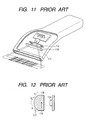
- Japanese patent application provisional publication No. 9-128473 discloses another prior art optical data form reading apparatus as a bar code reader.
- Fig. 11 is a perspective view, partly a cut view, of this prior art bar code reader.
- Fig. 12 is a sectional view of the cylindrical lens 118 for this prior art bar code reader.
- the cylindrical lens 118 has a curved surface 117 as shown in Fig. 12.
- the curved surface 117 has successive three curvatures a, b, and c on the sectional plane in Fig. 12 to condense light from the LEDs 116 to adjust an illumination pattern to the reading area.
- the shape of the sectional area does not vary along the axis 119 of the cylindrical surface 117.
- the aim of the present invention is to provide a superior optical data form reading apparatus.
- a first aspect of the present invention provides an optical data form reading apparatus comprising an objective lens; an optical sensor having a plurality of photosensitive elements arranged in a first direction which is perpendicular to an optical axis defined by said objective lens; a light emitting means for emitting illumination light; and a projection lens for condensing and projecting said illumination light on a readable target, said objective lens focusing reflected light from said readable target onto said optical sensor to generate an optical detection signal from said optical sensor, wherein said projection lens has at least a convex surface having curvature in a second direction which varies in said first direction to make said illumination light substantially collimated regarding said second direction along said projection lens in said first direction, and said second direction is perpendicular to said first direction and said optical axis.
- a second aspect of the present invention provides an optical data form reading apparatus based on the first aspect, wherein said light emitting means includes a plurality of light emitting elements arranged in said first direction beside said optical axis, said projection lens is arranged between said light emitting means and a reading plane of said readable target and extends in a third direction which is inclined to said optical axis, said convex surface curves only in said second direction, and said curvature just in front of each of said light emitting elements provides a focus point substantially at each of said light emitting elements.
- a fourth aspect of the present invention provides an optical data form reading apparatus comprising: an objective lens; an optical sensor having a plurality of photosensitive elements arranged in a first direction which is perpendicular to an optical axis defined by said object lens; a light emitting linear array including a plurality of light emitting elements arranged in said first direction for emitting illumination light; and a projection lens for condensing and projecting said illumination light on a readable target, said objective lens focusing reflected light from said readable target onto said optical sensor to generate an optical detection signal from said optical sensor, wherein said projection lens has at least a convex surface having curvature in a second direction varies in said first direction to make said illumination light substantially collimated regarding said second direction along said projection lens in said first direction, and said second direction is perpendicular to said first direction and said optical axis.
- a fifth aspect of the present invention provides an optical data form reading apparatus based on the fourth aspect, wherein said projection lens is arranged between said light emitting linear array and a reading plane of said readable target and extends in a third direction which is inclined to said optical axis, said convex surface curves only in said second direction, and said curvature just in front of each of said light emitting elements provides a focus point substantially at each of said light emitting elements.
- a seventh aspect of the present invention provides an optical data form reading apparatus comprising an objective lens; an optical sensor having a plurality of photosensitive elements arranged in a first direction which is perpendicular to an optical axis defined by said object lens; light emitting means including a plurality of light emitting elements arranged in said first direction for emitting illumination light; and condensing means for condensing and projecting said illumination light on optical data form, said objective lens focusing reflected light from said optical data form onto said optical sensor to generate an optical detection signal indicative of said optical data form from said optical sensor, wherein said projection lens has at least a convex surface having curvature in a second direction varies in said first direction to make said illumination light substantially collimated such that a width an illuminated pattern on a reading plane of said optical data form in said second direction is substantially constant, and said second direction is perpendicular to said first direction and said optical axis.
- an eighth aspect of the present invention provides an optical data form reading apparatus based on the seventh aspect, wherein said light emitting means is arranged beside said optical axis, said projection lens is arranged between said light emitting means and a reading plane of said optical data form and extends in a third direction which is inclined to said optical axis, said convex surface curves only in said second direction, and said curvature just in front of each of said light emitting elements provides a focus point substantially at each of said photosensitive element.
- a bar code reader will be described as an optical data form reading apparatus according to an embodiment of the present invention with reference to Figs. 1 to 6.
- Fig. 5 shows an outline structure of the bar code reader 11.
- Fig. 6 shows a sectional side elevation view of the bar code reader 11.
- the bar code reader 11 includes a portable case 12.
- the portable case 12 contains and supports a printed circuit board 16.
- the printed circuit board 16 supports a display 14 and key switches 15 on one surface thereof as shown.
- On the other surface of the printed circuit board 16 a line sensor 17 is arranged. In front of the line sensor 17, an objective lens 20 is arranged on the printed circuit board 16.
- Fig. 1 shows a sectional plan view of the bar code reader 11.
- the line sensor 17 includes a plurality of photosensitive elements 30 aligned in line in a first direction 31.
- the line sensor 17 generates an image detection signal 32 indicative of the bar code image from the image formed thereon.
- the objective lens 20 has an optical axis C and a plurality of photosensitive elements 30 are arranged in the first direction 31 perpendicular to the optical axis C.
- the printed circuit board 16 further includes a microprocessor (not shown) for processing the image detection signal to detect the code indicated by the bar codes and executing processes in response to the key switches 15.
- the portable case 12 has a reading opening 18 at one end thereof. Near the reading opening 18, a mirror 19 is provided on the optical axis C to direct the light from the reading opening 18 to the objective lens 20 and the line sensor 17. That is, the mirror 19 bends the optical axis C. Hence, the mirror 19 reflects the image of bar codes on a label L to direct the beam of the image to the objective lens 20.
- the objective lens 20 arranged between the mirror 19 and the line sensor 17 focuses the image of the bar codes on the line sensor 17.
- the reading opening 18 has a rectangular shape on a cross-sectional plane thereof, wherein the longitudinal side thereof (width direction) extends in the first direction 31.
- the printed circuit board 22 extends in the first direction.
- LED arrays 23a are arranged beside the axis C (on both sides of the axis C) substantially in the first direction 31.
- Each LED arrays 23a includes LEDs 23 arranged in the first direction 31.
- projection lenses 24 are arranged, respectively.
- Each of projection lenses 24 extends in a third direction (extending direction) 38 which has an inclined angle ⁇ (not 90°) from the axis C to direct the illumination light therefrom toward a reading plane 34 where the label L is placed.
- the extending direction is inclined from the first direction 31 by ⁇ .
- the reading plane 34 is normal to the axis C and at a predetermined distance D from the objective lens 20 to focus the image of the bar codes on the surface of the line sensor 17.
- the projection lens 24 is made of plastic and has a half circular bar shape extending in the third direction 38.
- the projection lens 24 has a flat surface 24b on the side of the LED arrays 23a and a convex surface 24a of which curvature varies along the projection lens 24 (in the first direction 31 or the third direction 38).
- the convex surface 24a has a curvature of a radius r1 which is greater than the curvature of a radius r2 at the other (inner) end of the projection lens 24.
- the projection lens 23 collimates the illumination light 33 to generate the collimated light 36 regarding the second direction 37.
- the second direction 37 is perpendicular to the optical axis C and the first direction 31.
- the distance between the LED 23c near the portable case 12 and the projection lens 24 is greater than that of the LED 23b near the optical axis C, so that the radius r1 is smaller than the radius r2 at the side of the LED 23b for collimation. That is, the shorter distance requires the shorter radius of the curvature of the lens surface.
- the radius successively varies along the third direction 38. However, it is also possible that the curvature varies stepwise.
- the projection lens 24 has at least a convex surface 24a of which curvatures r1, r2 are arranged substantially in the first direction 31 and varies in the first direction 31 to make the illumination light substantially collimated regarding the second direction 37 along the projection lens 24 (in the third direction 38).
- each LED 23 In general convex lenses, if the curvature varies, the focal distance will varies. Thus, in the above-mentioned projection lens 24, the focal distance varies along its extending direction 38. A radius just in front of (confronting) each LED 23 is determined such that the position of the LED 23 agrees with the focal point derived from the radius there. That is, the curvature confronting each of the LEDs 23 provides a focus point substantially at each of the LEDs 23.
- the radius of curvature Ra on the other side of the projection lens 24 at each point along its extending direction 38 is determined such that focal distance f at the point agrees with the distance between the projection lens 24 and each LED 23.
- each LED 23 positions at a focal point of the projection lens 24, the illumination light emitted by each LED 23 is condensed and made collimated.
- the collimated beam 36 is projected on bar codes on the label L (a readable target) such that the collimated beam provides an illuminated stripe 40 of which width W is substantially constant.
- brightness at the stripe 40 is constant along the stripe 40 (in the first direction 31) as shown in Fig. 4.
- the reflected light 35 from the label L is focused onto the line sensor 17 to form a data form image there.
- Fig. 7 is a perspective view showing a modification of a projection lens according to this invention.
- This projection lens 25 is provided for a portable two-dimensional code reader.
- This code reader includes an area sensor in which photosensitive elements are two-dimensionally arranged, for example, a CCD area sensor.
- the objective lens focuses the light reflected by a two-dimensional code on the area sensor.
- Around the objective lens a plurality of LEDs are equidistantly arranged from the axis of the objective lens at a regular angular position on a printed circuit board.
- the projection lens 25 is formed into substantially a bellmouthed shape to condense and project the illumination light from a plurality of LEDs on the two-dimensional cod label.
- the curvatures of the inner and outer surfaces vary in the arranging direction of the elements of the two-dimensional sensor, that is, the vertically and horizontal directions. This structure provides a circular spot illumination without unevenness in brightness on the two-dimensional code label.
- the number of the LED 23 in portable bar code reader 11 using the line sensor 17 may be one.
- the curvature is determined such that the focal distance at each point along the extending direction 38 agrees with the distance from each point to the position of the LED 23. Accordingly, the radius of the curvature just in front of (confronting) the LED 23 is smaller than radiuses at other points.
Landscapes
- Physics & Mathematics (AREA)
- Engineering & Computer Science (AREA)
- Electromagnetism (AREA)
- General Physics & Mathematics (AREA)
- General Health & Medical Sciences (AREA)
- Artificial Intelligence (AREA)
- Computer Vision & Pattern Recognition (AREA)
- Health & Medical Sciences (AREA)
- Theoretical Computer Science (AREA)
- Toxicology (AREA)
- Image Input (AREA)
- Lenses (AREA)
- Facsimile Scanning Arrangements (AREA)
- Facsimile Heads (AREA)
- Optical Head (AREA)
- Length Measuring Devices By Optical Means (AREA)
- Mechanical Optical Scanning Systems (AREA)
Abstract
Description
Claims (9)
- An optical data form reading apparatus comprising:an objective lens;an optical sensor having a plurality of photosensitive elements arranged in a first direction which is perpendicular to an optical axis defined by said objective lens;a light emitting means for emitting illumination light; anda projection lens for condensing and projecting said illumination light on a readable target, said objective lens focusing reflected light from said readable target on said optical sensor to generate an optical detection signal from said optical sensor, wherein said projection lens has at least a convex surface having curvature in a second direction which varies in said first direction to make said illumination light substantially collimated regarding said second direction along said projection lens in said first direction, and said second direction is perpendicular to said first direction and said optical axis.
- An optical data form reading apparatus as claimed in claim 1, wherein said light emitting means includes a plurality of light emitting elements arranged in said first direction beside said optical axis, said projection lens is arranged between said light emitting means and a reading plane of said readable target and extends in a third direction which is inclined to said optical axis, said convex surface curves only in said second direction, and said curvature just in front of each of said light emitting elements provides a focus point substantially at each of said light emitting elements.
- An optical data form reading apparatus as claimed in claim 2, wherein said projection lens has a flat surface on the side of said light emitting means and said convex surface at the other side, said convex surface curves only in said second direction, if it is assumed that said curvature at each point on said convex surface is Ra, a refraction index of said projection lens is n, and a focal distance at each point is f, (1/f) = (n-1)(1/Ra).
- An optical data form reading apparatus comprising:an objective lens;an optical sensor having a plurality of photosensitive elements arranged in a first direction which is perpendicular to an optical axis defined by said object lens;a light emitting linear array including a plurality of light emitting elements arranged in said first direction for emitting illumination light; anda projection lens for condensing and projecting said illumination light on a readable target, said objective lens focusing reflected light from said readable target on said optical sensor to generate an optical detection signal from said optical sensor, wherein said projection lens has at least a convex surface having curvature in a second direction which varies in said first direction to make said illumination light substantially collimated regarding said second direction along said projection lens in said first direction, and said second direction is perpendicular to said first direction and said optical axis.
- An optical data form reading apparatus as claimed in claim 4, wherein said projection lens is arranged between said light emitting linear array and a reading plane of said readable target and extends in a third direction which is inclined to said optical axis, said convex surface curves only in said second direction, and said curvature just in front of each of said light emitting elements provides a focus point substantially at each of said light emitting elements.
- An optical data form reading apparatus as claimed in claim 5, wherein said projection lens has a flat surface on the side of said light emitting array and said convex surface at the other side, said convex surface curves only in said second direction, if it is assumed that said curvature at each point on said convex surface is Ra, a refraction index of said projection lens is n, and a focal distance at each of said places is f, (1/f) = (n-1)(1/Ra).
- An optical data form reading apparatus comprising:an objective lens ;an optical sensor having a plurality of photosensitive elements arranged in a first direction which is perpendicular to an optical axis defined by said object lens;light emitting means including a plurality of light emitting elements arranged in said first direction for emitting illumination light; andcondensing means for condensing and projecting said illumination light on optical data form, said objective lens focusing reflected light from said optical data form onto said optical sensor to generate an optical detection signal indicative of said optical data form from said optical sensor, wherein said projection lens has at least a convex surface having curvature in a second direction which varies in said first direction to make said illumination light substantially collimated such that a width an illuminated pattern on a reading plane of said optical data form in said second direction is substantially constant, and said second direction is perpendicular to said first direction and said optical axis.
- An optical data form reading apparatus as claimed in claim 7, wherein said light emitting means is arranged beside said optical axis, said projection lens is arranged between said light emitting means and said reading plane of said optical data form and extends in a third direction which is inclined to said optical axis, said convex surface curves only in said second direction, and said curvature just in front of each of said light emitting elements provides a focus point substantially at each of said photosensitive element.
- An optical data form reading apparatus as claimed in claim 8, wherein said projection lens has a flat surface on the side of said light emitting means and said convex surface at the other side, said convex surface curves only in said second direction, if it is assumed that said curvature at each point on said convex surface is Ra, a refraction index of said projection lens is n, and a focal distance at each of said places is f, (1/f) = (n-1)(1/Ra).
Applications Claiming Priority (2)
| Application Number | Priority Date | Filing Date | Title |
|---|---|---|---|
| JP2000294095A JP3511991B2 (en) | 2000-09-27 | 2000-09-27 | Optical information reader |
| JP2000294095 | 2000-09-27 |
Publications (3)
| Publication Number | Publication Date |
|---|---|
| EP1193640A2 true EP1193640A2 (en) | 2002-04-03 |
| EP1193640A3 EP1193640A3 (en) | 2002-05-15 |
| EP1193640B1 EP1193640B1 (en) | 2008-02-27 |
Family
ID=18776767
Family Applications (1)
| Application Number | Title | Priority Date | Filing Date |
|---|---|---|---|
| EP01122894A Expired - Lifetime EP1193640B1 (en) | 2000-09-27 | 2001-09-24 | An optical data form reading apparatus |
Country Status (4)
| Country | Link |
|---|---|
| US (1) | US6698659B2 (en) |
| EP (1) | EP1193640B1 (en) |
| JP (1) | JP3511991B2 (en) |
| DE (1) | DE60132960T2 (en) |
Cited By (2)
| Publication number | Priority date | Publication date | Assignee | Title |
|---|---|---|---|---|
| EP1445639A1 (en) * | 2003-02-06 | 2004-08-11 | Hewlett-Packard Development Company, L.P. | Variable intensity illuminator lens |
| EP1701295A1 (en) * | 2005-03-07 | 2006-09-13 | TÜV Rheinland Industrie Service GmbH | Inspection tag |
Families Citing this family (8)
| Publication number | Priority date | Publication date | Assignee | Title |
|---|---|---|---|---|
| US7028899B2 (en) * | 1999-06-07 | 2006-04-18 | Metrologic Instruments, Inc. | Method of speckle-noise pattern reduction and apparatus therefore based on reducing the temporal-coherence of the planar laser illumination beam before it illuminates the target object by applying temporal phase modulation techniques during the transmission of the plib towards the target |
| JP2004170858A (en) * | 2002-11-22 | 2004-06-17 | Canon Inc | Image reading device |
| JP4169001B2 (en) * | 2004-08-19 | 2008-10-22 | 株式会社デンソーウェーブ | Optical information reader |
| JP4501801B2 (en) * | 2005-07-15 | 2010-07-14 | 株式会社デンソーウェーブ | Optical information reader |
| JP2007334423A (en) * | 2006-06-12 | 2007-12-27 | Shimatec:Kk | Automatic photographing device |
| JP4915321B2 (en) * | 2007-09-25 | 2012-04-11 | 株式会社デンソーウェーブ | Optical information reader |
| EP2657881B1 (en) * | 2012-04-27 | 2014-06-11 | Sick Ag | Illumination device and method for creating an illumination area |
| CN109299625B (en) * | 2018-10-15 | 2023-08-29 | 深圳市民德电子科技股份有限公司 | Image recognition equipment and illumination aiming structure thereof |
Family Cites Families (8)
| Publication number | Priority date | Publication date | Assignee | Title |
|---|---|---|---|---|
| US5280161A (en) | 1988-11-18 | 1994-01-18 | West Electric Company, Ltd. | Apparatus for optically reading a bar code |
| US5144117A (en) * | 1990-02-27 | 1992-09-01 | Alps Electric Co., Ltd. | Illumination type optical recorded information reading device |
| GB2257280A (en) * | 1991-06-26 | 1993-01-06 | Asahi Optical Co Ltd | Non-scanning bar code reading apparatus |
| US5354977A (en) | 1992-02-27 | 1994-10-11 | Alex Roustaei | Optical scanning head |
| US5349172A (en) | 1992-02-27 | 1994-09-20 | Alex Roustaei | Optical scanning head |
| JP2753980B2 (en) | 1995-10-31 | 1998-05-20 | 松下電器産業株式会社 | Barcode reader |
| US6123263A (en) * | 1998-01-29 | 2000-09-26 | Meta Holdings Corporation | Hand held dataform reader having strobing ultraviolet light illumination assembly for reading fluorescent dataforms |
| JP2000231598A (en) | 1999-02-12 | 2000-08-22 | Victor Co Of Japan Ltd | Bar code reader |
-
2000
- 2000-09-27 JP JP2000294095A patent/JP3511991B2/en not_active Expired - Fee Related
-
2001
- 2001-09-13 US US09/950,800 patent/US6698659B2/en not_active Expired - Lifetime
- 2001-09-24 DE DE60132960T patent/DE60132960T2/en not_active Expired - Lifetime
- 2001-09-24 EP EP01122894A patent/EP1193640B1/en not_active Expired - Lifetime
Cited By (3)
| Publication number | Priority date | Publication date | Assignee | Title |
|---|---|---|---|---|
| EP1445639A1 (en) * | 2003-02-06 | 2004-08-11 | Hewlett-Packard Development Company, L.P. | Variable intensity illuminator lens |
| US6866405B2 (en) | 2003-02-06 | 2005-03-15 | Hewlett-Packard Development Company, L.P. | Variable intensity illuminator lens |
| EP1701295A1 (en) * | 2005-03-07 | 2006-09-13 | TÜV Rheinland Industrie Service GmbH | Inspection tag |
Also Published As
| Publication number | Publication date |
|---|---|
| DE60132960D1 (en) | 2008-04-10 |
| JP2002111970A (en) | 2002-04-12 |
| US20020036233A1 (en) | 2002-03-28 |
| EP1193640B1 (en) | 2008-02-27 |
| JP3511991B2 (en) | 2004-03-29 |
| US6698659B2 (en) | 2004-03-02 |
| EP1193640A3 (en) | 2002-05-15 |
| DE60132960T2 (en) | 2009-04-16 |
Similar Documents
| Publication | Publication Date | Title |
|---|---|---|
| US7967210B2 (en) | Imaging bar code reader having light emitting diode for generating a field of view | |
| JP4515502B2 (en) | Aiming light pattern generator of an imaging reader that reads indicia electro-optically | |
| US7726573B2 (en) | Compact autofocus bar code reader with moving mirror | |
| KR100964914B1 (en) | Information reading device for optically reading code | |
| EP1804089B1 (en) | Illumination lens for an optical code reader | |
| US6698659B2 (en) | Optical data form reading apparatus | |
| KR20180019724A (en) | Light emitting device | |
| US8028919B2 (en) | Imaging bar code reader with single prism focus adjustment | |
| US7252237B2 (en) | Code reader | |
| JP2003308475A (en) | Optical information reading device | |
| US8181877B2 (en) | Aiming device | |
| US7360704B2 (en) | Scan engine with guiding light beams | |
| JP2024113915A (en) | Portable code reading device and code reading method | |
| US6866405B2 (en) | Variable intensity illuminator lens |
Legal Events
| Date | Code | Title | Description |
|---|---|---|---|
| PUAI | Public reference made under article 153(3) epc to a published international application that has entered the european phase |
Free format text: ORIGINAL CODE: 0009012 |
|
| PUAL | Search report despatched |
Free format text: ORIGINAL CODE: 0009013 |
|
| AK | Designated contracting states |
Kind code of ref document: A2 Designated state(s): AT BE CH CY DE DK ES FI FR GB GR IE IT LI LU MC NL PT SE TR |
|
| AX | Request for extension of the european patent |
Free format text: AL;LT;LV;MK;RO;SI |
|
| AK | Designated contracting states |
Kind code of ref document: A3 Designated state(s): AT BE CH CY DE DK ES FI FR GB GR IE IT LI LU MC NL PT SE TR |
|
| AX | Request for extension of the european patent |
Free format text: AL;LT;LV;MK;RO;SI |
|
| 17P | Request for examination filed |
Effective date: 20020627 |
|
| AKX | Designation fees paid |
Designated state(s): DE FR GB |
|
| GRAP | Despatch of communication of intention to grant a patent |
Free format text: ORIGINAL CODE: EPIDOSNIGR1 |
|
| GRAS | Grant fee paid |
Free format text: ORIGINAL CODE: EPIDOSNIGR3 |
|
| GRAA | (expected) grant |
Free format text: ORIGINAL CODE: 0009210 |
|
| AK | Designated contracting states |
Kind code of ref document: B1 Designated state(s): DE FR GB |
|
| REG | Reference to a national code |
Ref country code: GB Ref legal event code: FG4D |
|
| REF | Corresponds to: |
Ref document number: 60132960 Country of ref document: DE Date of ref document: 20080410 Kind code of ref document: P |
|
| REG | Reference to a national code |
Ref country code: GB Ref legal event code: 746 Effective date: 20080819 |
|
| ET | Fr: translation filed | ||
| PLBE | No opposition filed within time limit |
Free format text: ORIGINAL CODE: 0009261 |
|
| STAA | Information on the status of an ep patent application or granted ep patent |
Free format text: STATUS: NO OPPOSITION FILED WITHIN TIME LIMIT |
|
| 26N | No opposition filed |
Effective date: 20081128 |
|
| REG | Reference to a national code |
Ref country code: FR Ref legal event code: PLFP Year of fee payment: 15 |
|
| REG | Reference to a national code |
Ref country code: FR Ref legal event code: PLFP Year of fee payment: 16 |
|
| REG | Reference to a national code |
Ref country code: FR Ref legal event code: PLFP Year of fee payment: 17 |
|
| REG | Reference to a national code |
Ref country code: FR Ref legal event code: PLFP Year of fee payment: 18 |
|
| PGFP | Annual fee paid to national office [announced via postgrant information from national office to epo] |
Ref country code: DE Payment date: 20180920 Year of fee payment: 18 Ref country code: FR Payment date: 20180924 Year of fee payment: 18 |
|
| PGFP | Annual fee paid to national office [announced via postgrant information from national office to epo] |
Ref country code: GB Payment date: 20180919 Year of fee payment: 18 |
|
| REG | Reference to a national code |
Ref country code: DE Ref legal event code: R119 Ref document number: 60132960 Country of ref document: DE |
|
| PG25 | Lapsed in a contracting state [announced via postgrant information from national office to epo] |
Ref country code: DE Free format text: LAPSE BECAUSE OF NON-PAYMENT OF DUE FEES Effective date: 20200401 |
|
| GBPC | Gb: european patent ceased through non-payment of renewal fee |
Effective date: 20190924 |
|
| PG25 | Lapsed in a contracting state [announced via postgrant information from national office to epo] |
Ref country code: GB Free format text: LAPSE BECAUSE OF NON-PAYMENT OF DUE FEES Effective date: 20190924 Ref country code: FR Free format text: LAPSE BECAUSE OF NON-PAYMENT OF DUE FEES Effective date: 20190930 |