EP1193470A2 - Detecting material failures in ground locations - Google Patents
Detecting material failures in ground locations Download PDFInfo
- Publication number
- EP1193470A2 EP1193470A2 EP01203555A EP01203555A EP1193470A2 EP 1193470 A2 EP1193470 A2 EP 1193470A2 EP 01203555 A EP01203555 A EP 01203555A EP 01203555 A EP01203555 A EP 01203555A EP 1193470 A2 EP1193470 A2 EP 1193470A2
- Authority
- EP
- European Patent Office
- Prior art keywords
- man
- digital images
- images
- ground
- failures
- Prior art date
- Legal status (The legal status is an assumption and is not a legal conclusion. Google has not performed a legal analysis and makes no representation as to the accuracy of the status listed.)
- Withdrawn
Links
Images


Classifications
-
- G—PHYSICS
- G01—MEASURING; TESTING
- G01C—MEASURING DISTANCES, LEVELS OR BEARINGS; SURVEYING; NAVIGATION; GYROSCOPIC INSTRUMENTS; PHOTOGRAMMETRY OR VIDEOGRAMMETRY
- G01C11/00—Photogrammetry or videogrammetry, e.g. stereogrammetry; Photographic surveying
- G01C11/04—Interpretation of pictures
- G01C11/06—Interpretation of pictures by comparison of two or more pictures of the same area
Definitions
- the present invention relates to remotely detecting material failures in a ground location by using an image sensor.
- ground topography The surveillance of ground topography is well known in the art. It is frequently the case that an aircraft or a satellite includes an image capture device such as a CCD. In ground surveillance it is highly desirable to detect whether there has been a material failure in a man-made object such as a road, a pipeline, an electrical grid, or other man-made structures of practical interest. When detected, a determination is made if remedial action must be taken. Often times a visual inspection of ground topography is provided by a land-based crew that traverses an area by vehicle or foot, to determine if there is a material failure. Airborne photographic systems can also be used for capturing images of adjacent areas. These images are then reviewed to determine if there is a material failure.
- This object is achieved by a method for capturing images of ground locations and for detecting the presence of material failures in man-made structures in such ground locations comprising the steps of:
- a feature of the present invention is that a chemical agent or a chemical change associated with a material failure can be used in a man-made structure of practical interest that is particularly suitable for detection after a material failure.
- a sensor system 1 employed in the capturing of images in order to identify material failures in man-made structures may be mounted on either an aerial or a satellite platform. Images of the ground containing various man-made structures such as roadways, pipelines, electrical power lines, agricultural, mining, real estate activity and the like are captured by this sensor system1.
- the term "man-made structure" can also include other human activities such as insecticide spraying which after application can be detected by sensor system 1. In such a case, an additive can be included in the insecticide spray that can be detected by the image sensor.
- Sequential images may be captured in digital form and either stored in the aerial or satellite platform to be transferred later or transmitted via a radio link to a control ground station.
- the capture device 2 includes an electronic sensor, typically a CCD or CMOS imaging array that along with some imaging optics captures a picture of the scene in electronic form.
- a special optical filter 3 is attached to the input to the CCD or CMOS detector to filter the light wavelengths which are incident upon the detector. This optical filter 3 is chosen so as to maximize the signal-to-noise ratio for the detection of a specific type of material failure.
- the ground location image can be captured by conventional photographic cameras. Film images would then have to be converted to digital images by an image scanner that includes an image sensor.
- the system 1 also has an image capture control circuit 4 that sequences the operation of the capture device 2. As will be clear from FIG. 1, the operation of the various elements shown in system 1 are under the control of a control computer 31.
- the image capture control circuit 4 controls capture device 2 and sends position and orientation information to a position and orientation storage circuit 5 with each captured image.
- Position information in the form of spatial coordinates is provided by the customer in order to identify the location of man-made structures of interest. Such position information is also stored in position and orientation storage circuit 5.
- Position and orientation data are used along with predetermined coordinate positions to locate the man-made structures in the captured image.
- Control computer 31 causes image data to be stored in image storage 6 and can be processed to identify features of a scene in image processing circuit 7. The processing sequence is also directed by control computer 31 of the image data in this instance is to enhance the capability of the system 1 to identify material failures in man-made structures.
- the image processing circuit 7 includes a storage memory (not shown) that includes a representation of different material failures to be detected and comparing the captured digital image with the material failures to determine the presence of a material failure, type of material failures and location of the material failures.
- a storage memory not shown
- the various elements of the system 1 may be located either in the remote platform or at the ground station location.
- many of the elements described can be embodied in software which can be understood to be within the control computer 31.
- the capture device 2 is located in either the aerial or satellite platform or a fixed structure spaced above the ground.
- the overall process for detecting material failures in man-made structures is depicted in flowchart form in FIG. 2.
- the flowchart is in block diagram form and those skilled in the art will appreciate that many of the functions are controlled by the control computer 31.
- the starting event includes initializing the capture device 2 and image storage 6 to erase any previously captured scene data.
- a new scene is captured in block 9 using the position information supplied by the customer to trigger recording of the images.
- the image data along with position and time information necessary to identify the location and time of the current scene is stored in order to facilitate comparison with the same scene taken at other times.
- Image and other data are stored in a scene database 10 in order to perform such comparisons at a future time.
- Image analysis 11 is next performed in order to identify changes in the scene and facilitate identification of material failures in the man-made structures that appear in the scene.
- the latest scene image is compared with image data that has been previously stored in the scene database 10. If a material failure is not detected the process stops. Detection of a material failure may initiate further image analysis 12 as required by a customer 13.
- the identification process finishes with the results of the analysis communicated to the customer 13.
- the communication take many forms, for example a telephone contact or e-mail notification of the detection of the material failure.
- the final step in the process is to correct the material failure.
- FIG. 3 depicts the algorithm used to process image data files from a database and identifies material failures if they have occurred.
- Two separate data files, scene (1) 14 and scene (2) 15, are made available for comparison. Both data files contain the same scene content, but they typically record images taken at different times. That is, the time between capturing the two images differs by a time ⁇ t.
- Both image files or scenes undergo the process of orthorectification 16, that is, compensation for variations in position and angle at the time the scenes were recorded. This process is performed in order to allow an exact pixel by pixel comparison of the elements of a scene or image. It may or may not be necessary to correct the data in each scene for differences in the illumination 17 at the time each scene was recorded.
- Changes in the scene are identified in block 18 are used by the control computer 31 by detecting, using software, differences in the pixel content of the two scenes to be compared. Such changes may be reflected in the intensity of the pixels, or in the shape of an object, corresponding to a finite collection of pixels. Such methods for identification of pixel or object changes are well known to those skilled in the art. On the basis of such pixel changes the material failure type is identified in block 19 and the customer 13 is notified 20 of the existence of the failure.
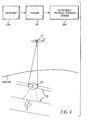
- FIG. 4 illustrates a somewhat different embodiment of the present invention that uses an agent to aid in detecting material failures in a man-made object.
- An aerial platform 21 performs image capture 22 of a man-made structure (in this case a roadway, 23) in the manner previously described.
- FIG. 4 also shows image capture of a roadway 23 with an isolated man-made failure 24.
- the detection of the man-made material failure is enhanced by the presence of a chemical or physical image contrast-enhancing agent.
- the contrast agent for example, could be released to the environment as a consequence of the material failure occurring.
- encapsulated fluorescent dyes either as isolated molecular species or in crystalline form, embedded in a roadway could be released with crack formation.
- Triboluminescent materials that emit light upon mechanical impact could be sensed to determine the likelihood of material failure as a result of mechanical impact.
- Yellow-emitting halophosphate phosphors are well established as sensors when used in this mode of operation.
- the contrast agent is incorporated into a man-made structure in a form where it becomes activated upon the occurrence of a material failure.
- certain chemical species may undergo a color change upon exposure to air or other chemical species.
- An example is the use of corrosion-sensitive paints applied to pipelines.
- Color-changing chemical compounds (indicators) such as phenolphthalein or bromothymol blue, or fluorescing chemical compounds such as coumarins, can be incorporated into acrylic paints and applied to pipelines.
- Corrosion of the pipe causes a pH change in the paint; the consequence of which is a color change in the indicator or fluorescence. Such color changes are recorded remotely.
- Color-change materials exist that are sensitive to changes in pH, oxygen concentration, and the presence of trace quantities of various metal ions in the environment (chelating agents). The use of such materials is well known to those skilled in the art, and may be used singly or in combination, in remote sensing applications.
- Such materials in combination with the optical filter 3 in FIG. 1 significantly improve the signal-to-noise ratio, and hence the detectability for remote sensing.
- the combination of the optical filter transmission function and the color-change to be detected as a result of a material failure will be optimized for each application. This optimization is well known to those skilled in the art.
- FIG 5 illustrates the capturing of an image, analysis to identify a material failure and communication over a computer network to deliver information to and receive payment from the customer 13.
- a satellite 25 or an aerial platform 26 captures an image of a scene 27 that contains a man-made structure (in this case electrical utility lines) to be analyzed.
- the image data is transmitted to a ground station 28 and transferred to the service provider's computer system 29.
- the image data is analyzed as previously described to determine whether a material failure has occurred. If a failure is detected the customer 13 for the service receives notification of the failure via a channel for example, a computer network such as the Internet, or via other means, such as telephony.
- the customer computer 30 receives the notification directly from over the computer network.
- the customer 13 subscribes to the service and pays for the service via the computer network. In this manner, the timely delivery of information regarding the status of a failure can be transmitted to the customer and the quality of service can be assured to be at a sufficiently high
- the method further including providing a chemical agent that includes which materials which when released reacts with substances in the ground to provide a detectable material failure to the image sensor.
- the method wherein the image processing includes comparing previously captured images with newly captured images to determine variations in a ground condition which could contain the material failure.
Landscapes
- Engineering & Computer Science (AREA)
- Multimedia (AREA)
- Physics & Mathematics (AREA)
- General Physics & Mathematics (AREA)
- Radar, Positioning & Navigation (AREA)
- Remote Sensing (AREA)
- Image Processing (AREA)
- Geophysics And Detection Of Objects (AREA)
- Investigating Materials By The Use Of Optical Means Adapted For Particular Applications (AREA)
- Processing Or Creating Images (AREA)
- Image Analysis (AREA)
Abstract
Description
Claims (10)
- A method for capturing images of ground locations and for detecting the presence of material failure(s) or failures in man-made structures in such ground locations comprising the steps of:(a) providing an image sensor spaced remotely from the ground and which sequentially captures a number of images of various ground locations to provide digital images;(b) processing captured digital images to determine the presence of a potential material failure in a man-made structure in accordance with predetermined coordinate positions which locate the man-made structures in one or more of the captured digital images; and(c) indicating to a customer that a potential material failure has been detected in a predetermined coordinate position.
- The method of claim 1 further including:(d) sending captured processed digital images with detected potential material failures to a customer.
- The method of claim 1 wherein the digital image processing includes comparing previously captured digital images with newly captured digital images to determine variations in the captured digital images at the predetermined coordinates which indicate a potential material failure in a man-made structure.
- The method according to claim 1 wherein the digital images are captured by a capture device which is located in a fixed structure position above the ground location or in a moving structure such as an aircraft or satellite.
- The method of claim 3 wherein the image processing includes storing in memory a representation of different material failures to be detected and comparing the captured digital image with the material failures to determine the presence of a material failure, type of material failures and location of the material failures.
- A method for capturing images of ground locations and for detecting the presence of material failure(s) or failures in man-made structures having a detectable chemical agent in such ground locations comprising the steps of:(a) providing an image sensor spaced remotely from the ground and which sequentially captures a number of images of various ground locations to provide digital images;(b) processing captured digital images to determine changes in the chemical agent which indicate the presence of a potential material failure in a man-made structure in accordance with predetermined coordinate positions which locate the man-made structures in one or more of the captured digital images; and(c) indicating to a customer that a potential material failure has been detected in a predetermined coordinate position.
- The method of claim 6 wherein the chemical agent includes materials which when leaked from a receptacle are adapted to be detected.
- The method of claim 6 wherein the chemical agent includes materials which when released react with substances in the ground to provide a detectable material failure to the image sensor.
- A method for capturing images of ground locations and for detecting the presence of material failure(s) or failures in man-made structures in such ground locations comprising the steps of:(a) providing an image sensor spaced remotely from the ground and which sequentially captures a number of images of various ground locations to provide digital images;(b) processing captured digital images to determine the presence of a potential material failure in a man-made structure in accordance with predetermined coordinate positions which locate the man-made structures in one or more of the captured digital images;(c) indicating to a customer that a potential material failure has been detected in a predetermined coordinate position; and(d) correcting material failures.
- A method for capturing images of ground locations and for detecting the presence of failure(s) or material failures in man-made structures in such ground locations and making payment for the detection or correction of detected material failures comprising the steps of:(a) providing an image sensor spaced remotely from the ground and which sequentially captures a number of images of various ground locations to provide digital images;(b) processing captured digital images to determine the presence of a potential material failure in a man-made structure in accordance with predetermined coordinate positions which locate the man-made structures in one or more of the captured digital images;(c) indicating to a customer that a potential material failure has been detected in a predetermined coordinate position;(d) correcting material failures; and(e) making payment for the material failure.
Applications Claiming Priority (2)
| Application Number | Priority Date | Filing Date | Title |
|---|---|---|---|
| US672281 | 2000-09-28 | ||
| US09/672,281 US6842534B1 (en) | 2000-09-28 | 2000-09-28 | Detecting material failures in ground locations |
Publications (2)
| Publication Number | Publication Date |
|---|---|
| EP1193470A2 true EP1193470A2 (en) | 2002-04-03 |
| EP1193470A3 EP1193470A3 (en) | 2003-12-03 |
Family
ID=24697902
Family Applications (1)
| Application Number | Title | Priority Date | Filing Date |
|---|---|---|---|
| EP01203555A Withdrawn EP1193470A3 (en) | 2000-09-28 | 2001-09-19 | Detecting material failures in ground locations |
Country Status (3)
| Country | Link |
|---|---|
| US (1) | US6842534B1 (en) |
| EP (1) | EP1193470A3 (en) |
| JP (1) | JP2002175517A (en) |
Cited By (5)
| Publication number | Priority date | Publication date | Assignee | Title |
|---|---|---|---|---|
| EP1248074A3 (en) * | 2001-04-06 | 2003-11-05 | Eastman Kodak Company | Detecting the presence of failure(s) in existing man-made structures |
| EP1416258A1 (en) * | 2002-10-31 | 2004-05-06 | Eastman Kodak Company | Detecting natural gas pipeline failures |
| US7312452B2 (en) | 2003-04-24 | 2007-12-25 | Deutsches Zentrum Fur Luft- Und Raumfahrt E.V. | Mobile remote detection device and remote detection method for methane gas accumulations |
| EP2679973A1 (en) * | 2012-06-28 | 2014-01-01 | Commissariat A L'energie Atomique Et Aux Energies Alternatives | Location of a leak in a pipeline |
| CN107607543A (en) * | 2017-09-08 | 2018-01-19 | 上海振华重工(集团)股份有限公司 | The inspection device and method for inspecting of harbour machinery |
Families Citing this family (7)
| Publication number | Priority date | Publication date | Assignee | Title |
|---|---|---|---|---|
| EP1590692A2 (en) * | 2003-01-30 | 2005-11-02 | DEL GRANDE, Nancy K. | Thermal imaging method to detect subsurface objects |
| US8044437B1 (en) * | 2005-05-16 | 2011-10-25 | Lsi Logic Corporation | Integrated circuit cell architecture configurable for memory or logic elements |
| CN101364259B (en) * | 2008-04-09 | 2010-06-02 | 武汉大学 | Road Change Information Extraction Method for Panchromatic Remote Sensing Image Driven by Multi-level Knowledge |
| FR2953313B1 (en) * | 2009-11-27 | 2012-09-21 | Thales Sa | OPTRONIC SYSTEM AND METHOD FOR PREPARING THREE-DIMENSIONAL IMAGES FOR IDENTIFICATION |
| US20150300148A1 (en) * | 2014-04-16 | 2015-10-22 | Trc Services, Inc. | Methods of inspecting oilfield tools |
| JP2015220693A (en) * | 2014-05-20 | 2015-12-07 | キヤノン株式会社 | Imaging apparatus, imaging system, control method therefor, and program |
| CN106548469A (en) * | 2016-10-14 | 2017-03-29 | 深圳市深水水务咨询有限公司 | A kind of method for detecting pipeline and device |
Family Cites Families (23)
| Publication number | Priority date | Publication date | Assignee | Title |
|---|---|---|---|---|
| US4037189A (en) * | 1975-10-20 | 1977-07-19 | Western Gear Corporation | Method and apparatus for determining the profile of an underwater pipeline |
| US5026141A (en) * | 1981-08-24 | 1991-06-25 | G2 Systems Corporation | Structural monitoring system using fiber optics |
| US4653316A (en) * | 1986-03-14 | 1987-03-31 | Kabushiki Kaisha Komatsu Seisakusho | Apparatus mounted on vehicles for detecting road surface conditions |
| GB8619910D0 (en) | 1986-08-15 | 1986-09-24 | British Aerospace | Detection of damage in structural materials |
| US4987412A (en) * | 1988-08-25 | 1991-01-22 | The United States Of America As Represented By The United States Department Of Energy | Method and apparatus for the simultaneous display and correlation of independently generated images |
| US5126654A (en) * | 1989-02-10 | 1992-06-30 | New York Gas Group | Non-invasive, high resolution detection of electrical currents and electrochemical impedances at spaced localities along a pipeline |
| JPH06103967B2 (en) * | 1989-07-26 | 1994-12-14 | 三菱電機株式会社 | Image processor for overhead line inspection |
| JPH03215334A (en) | 1990-01-19 | 1991-09-20 | Yujiro Komatsu | Aggregate for discovering crack of concrete |
| US5042055A (en) * | 1990-03-12 | 1991-08-20 | Art Wirt | X-ray threaded pipe joint analysis system |
| JPH04240555A (en) * | 1991-01-23 | 1992-08-27 | Tokimec Inc | Apparatus for measuring crack of road surface |
| US5557518A (en) * | 1994-04-28 | 1996-09-17 | Citibank, N.A. | Trusted agents for open electronic commerce |
| US5444241A (en) * | 1993-10-01 | 1995-08-22 | The Regents Of The University Of California | Emissivity corrected infrared method for imaging anomalous structural heat flows |
| JP3376090B2 (en) | 1994-04-14 | 2003-02-10 | 株式会社常盤産業 | Inspection method of seal failure of package |
| JP2816950B2 (en) * | 1995-06-13 | 1998-10-27 | 中国電力株式会社 | Transmission line construction site management system and site photo transmission method |
| US5686674A (en) * | 1995-08-14 | 1997-11-11 | Science And Engineering Associates, Inc. | System for characterizing surfaces of pipes, ducts or similar structures |
| JP3199108B2 (en) * | 1995-11-20 | 2001-08-13 | 株式会社大林組 | Concrete member and its crack detection method |
| US5657003A (en) * | 1996-02-26 | 1997-08-12 | Fuentes; Alfredo | Structure movement monitoring and emergency alarm system |
| US5817945A (en) | 1996-04-15 | 1998-10-06 | Mcdonnell Douglas | System and method of determining strain |
| US5656786A (en) * | 1996-05-03 | 1997-08-12 | Ico, Inc. | Oilfield tubular inspection method and apparatus |
| US6178253B1 (en) * | 1997-10-10 | 2001-01-23 | Case Corporation | Method of determining and treating the health of a crop |
| AUPP107597A0 (en) | 1997-12-22 | 1998-01-22 | Commonwealth Scientific And Industrial Research Organisation | Road pavement deterioration inspection system |
| US6560729B1 (en) * | 2000-07-03 | 2003-05-06 | Advanced Micro Devices, Inc. | Automated determination and display of the physical location of a failed cell in an array of memory cells |
| US6952487B2 (en) | 2001-04-06 | 2005-10-04 | Itt Manufacturing Enterprises, Inc. | Detecting the presence of failure(s) in existing man-made structures |
-
2000
- 2000-09-28 US US09/672,281 patent/US6842534B1/en not_active Expired - Fee Related
-
2001
- 2001-09-19 JP JP2001285066A patent/JP2002175517A/en active Pending
- 2001-09-19 EP EP01203555A patent/EP1193470A3/en not_active Withdrawn
Cited By (10)
| Publication number | Priority date | Publication date | Assignee | Title |
|---|---|---|---|---|
| EP1248074A3 (en) * | 2001-04-06 | 2003-11-05 | Eastman Kodak Company | Detecting the presence of failure(s) in existing man-made structures |
| US6952487B2 (en) | 2001-04-06 | 2005-10-04 | Itt Manufacturing Enterprises, Inc. | Detecting the presence of failure(s) in existing man-made structures |
| EP1416258A1 (en) * | 2002-10-31 | 2004-05-06 | Eastman Kodak Company | Detecting natural gas pipeline failures |
| US7027924B2 (en) | 2002-10-31 | 2006-04-11 | Itt Manufacturing Enterprises, Inc | Detecting natural gas pipeline failures |
| US7312452B2 (en) | 2003-04-24 | 2007-12-25 | Deutsches Zentrum Fur Luft- Und Raumfahrt E.V. | Mobile remote detection device and remote detection method for methane gas accumulations |
| EP2679973A1 (en) * | 2012-06-28 | 2014-01-01 | Commissariat A L'energie Atomique Et Aux Energies Alternatives | Location of a leak in a pipeline |
| FR2992722A1 (en) * | 2012-06-28 | 2014-01-03 | Commissariat Energie Atomique | LOCALIZATION OF LEAKAGE IN A CANALIZATION |
| US9097605B2 (en) | 2012-06-28 | 2015-08-04 | Commissariat à l'énergie atomique et aux énergies alternatives | Location of a leak in a pipe |
| CN107607543A (en) * | 2017-09-08 | 2018-01-19 | 上海振华重工(集团)股份有限公司 | The inspection device and method for inspecting of harbour machinery |
| WO2019047338A1 (en) * | 2017-09-08 | 2019-03-14 | 上海振华重工(集团)股份有限公司 | Port machinery inspection device and inspection method |
Also Published As
| Publication number | Publication date |
|---|---|
| US6842534B1 (en) | 2005-01-11 |
| JP2002175517A (en) | 2002-06-21 |
| EP1193470A3 (en) | 2003-12-03 |
Similar Documents
| Publication | Publication Date | Title |
|---|---|---|
| US6987877B2 (en) | Superimposing graphic representations of ground locations onto ground location images after detection of failures | |
| US6952487B2 (en) | Detecting the presence of failure(s) in existing man-made structures | |
| US7027924B2 (en) | Detecting natural gas pipeline failures | |
| US6842534B1 (en) | Detecting material failures in ground locations | |
| CA2315188C (en) | Road pavement deterioration inspection system | |
| Chavez | Image-based atmospheric corrections-revisited and improved | |
| US8288726B2 (en) | Remote sensing of subsurface artifacts by use of visual and thermal imagery | |
| US20200125890A1 (en) | Systems and Methods for Identifying Threats and Locations, Systems and Method for Augmenting Real-Time Displays Demonstrating the Threat Location, and Systems and Methods for Responding to Threats | |
| KR101503213B1 (en) | Visual range measurement device and method using a geographical information and perspective of a visual image | |
| CN105911060B (en) | A kind of visible detection method and device of the pollution of transmission-type visual range visibility meter window mirror | |
| KR101954899B1 (en) | Method for automatic water level detection based on the intelligent CCTV | |
| JPWO2019064581A1 (en) | Construction machine inspection support system, management server and inspection report creation system | |
| EP3665512B1 (en) | Real-time computation of an atmospheric precipitation rate from a digital image of an environment where an atmospheric precipitation is taking place | |
| KR100715140B1 (en) | Visibility measuring apparatus and method | |
| KR101564223B1 (en) | Sewer inspection system to prevent sinkhole | |
| KR102673902B1 (en) | Radio frequency recognition tag-based object scanning device, indoor vehicle management system using same, and method therefor | |
| CN116631144A (en) | Disaster identification monitoring method and system for satellite optical remote sensor formation | |
| KR102133386B1 (en) | Safety inspection system for facilities to prevent leakage | |
| JP7833375B2 (en) | Communication system and shooting method | |
| AU740395B2 (en) | Road pavement deterioration inspection system | |
| US20250102424A1 (en) | Systems and Methods For An Open Path Gas Detector With An Integrated Optical Sensor | |
| JP2020027067A (en) | Container damage inspection device and container damage inspection method | |
| WO2023279079A1 (en) | Systems and methods for identifying threats and locations, systems and method for augmenting real-time displays demonstrating the threat location, and systems and methods for responding to threats | |
| WO2025109911A1 (en) | Information processing device, information processing method, and inspection system |
Legal Events
| Date | Code | Title | Description |
|---|---|---|---|
| PUAI | Public reference made under article 153(3) epc to a published international application that has entered the european phase |
Free format text: ORIGINAL CODE: 0009012 |
|
| AK | Designated contracting states |
Kind code of ref document: A2 Designated state(s): AT BE CH CY DE DK ES FI FR GB GR IE IT LI LU MC NL PT SE TR |
|
| AX | Request for extension of the european patent |
Free format text: AL;LT;LV;MK;RO;SI |
|
| PUAL | Search report despatched |
Free format text: ORIGINAL CODE: 0009013 |
|
| AK | Designated contracting states |
Kind code of ref document: A3 Designated state(s): AT BE CH CY DE DK ES FI FR GB GR IE IT LI LU MC NL PT SE TR |
|
| AX | Request for extension of the european patent |
Extension state: AL LT LV MK RO SI |
|
| 17P | Request for examination filed |
Effective date: 20040521 |
|
| AKX | Designation fees paid |
Designated state(s): DE FR GB |
|
| RAP1 | Party data changed (applicant data changed or rights of an application transferred) |
Owner name: ITT MANUFACTURING ENTERPRISES, INC. |
|
| 17Q | First examination report despatched |
Effective date: 20061110 |
|
| STAA | Information on the status of an ep patent application or granted ep patent |
Free format text: STATUS: THE APPLICATION HAS BEEN WITHDRAWN |
|
| 18W | Application withdrawn |
Effective date: 20110325 |