BACKGROUND OF THE INVENTION
Field of the Invention
The present invention relates methods of and apparatus for determining wood grain
orientation for use, for example, in lumber grading, defect inspection and quality control.
Description of the Related Art
The detection of wood grain orientation is normally carried out by human observation and
decision. However, modem forest industry requires scanning technology to measure wood
grain orientation automatically, reliably and precisely.
Wood is generally regarded as an orthogonal anisotropic material. The anatomic anisotropy
of wood cells gives rise to a grain structure with a grain orientation determined by
longitudinal axes of the wood cells. The interaction of wood materials with various types
of radiation brings about an anisotropic distribution of the radiation, which can be used as
an indication of the wood grain orientation.
Based on the anisotropic distribution of the dielectric constant of wood materials, a slope-of-grain
indicator (SGI) has been developed to determine the grain orientation of softwood
and hardwood species. For this purpose, a transducer with capacitor plates is mounted in
close proximity to a wood surface and rotated for dielectric constant scanning and sensing.
When the direction of an electric field applied to the capacitor plates is parallel to the wood
grain orientation, the transducer capacitance, which is proportional to the wood dielectric
constant, reaches its maximum. The resolution of the SGI depends on the transducer
diameter (3/4 or 1-3/8 inch). The speed could be up to 3600 rpm. The precision might
approach ±1°, provided the transducer-to-wood distance is maintained within a prescribed
limit (1/8 or 1/4 inch).
However, when SGI is employed, the measurement of the grain orientation is not
independent of the gradients of wood moisture and density. SGI is also sensitive to the
transducer-to-wood distance, unless the distance is maintained within the above prescribed
limit, resulting in close-contact measurement with less flexibility.
Based on the attenuation, phase shift and depolarization of a polarized microwave
transmitted through wood, a microwave transmission method has been suggested to probe
the amplitude, phase and polarization of a microwave field and to measure the moisture,
density and grain orientation of wood materials. Approximately, the attenuation reflects
moisture, the phase shift reflects both moisture and density, and the depolarization reflects
grain orientation. This method was improved to cope with the dependence of
depolarization on moisture and density, which makes grain orientation prediction rather
complicated. The experimental data show that the method can measure the grain
orientation reliably up to 30° at a speed up to 40 kHz and a resolution about 2 cm.
It is, however, a disadvantage of the microwave transmission method that calibrations are
complicated because of a considerable interaction between the parameters. The grain
orientation can be deduced reliably only when the specimen thickness and moisture are
great enough to introduce sufficient dielectric anisotropy to appreciably depolarize the
incident wave. The apparatus and techniques are very complex, although the principles and
experiments show the method to be feasible for on-line lumber grading by recording
moisture, density and grain orientation in real time.
Instead of employing human observation and decision, a scanning system consisting of a
camera and a computer for pattern recognition has been used to detect wood defects. This
system can be used to determine wood grain orientation based on wood splits, seasoning
checks, and mainly demarcations between earlywood and latewood. The precision and
speed depend on the algorithms designed for pattern recognition.
However, this scanning system for pattern recognition, which is time consuming, may not
give correct grain orientation because the demarcations between earlywood and latewood,
especially in the case of flatsawn surfaces, are not reliable indicators of grain orientation.
Several scanning systems based on the interaction of wood materials with laser light have
been proposed to detect wood grain orientation. When a laser light strikes a wood surface,
the laser light is split into two parts: a reflected light bouncing off the wood surface and a
transmitted light propagated in the wood material, which is an anisotropic absorbing
medium. Light propagated across wood cell walls will be attenuated more than light
propagated along wood cell lumens, where the attenuation constant of air or water is almost
zero. In the process of propagation, some of the transmitted light will emerge from the
wood surface, forming an elongate laser spot having its major axis along the grain
orientation as a result of the highly directional propagation beneath the wood surface.
Therefore, the light on the wood surface is a mixture of emergent laser light, reflected laser
light, and non-laser illumination.
The shape of the reflected laser spot is affected by wood surface qualities (planed, sanded,
or sawn). Generally, a roughsawn surface will cause more jagged edges on the reflected
laser spot than other wood surfaces. The elongate emergent laser spot (caused by wood cell
structure) is mixed with the jagged reflected laser spot (caused by wood surface
roughness), bringing about the inaccurate information of wood grain orientation.
The shape of the emergent laser spot is affected by wood species. Because the cells of
hardwood species are thicker and shorter than those of softwood species, the transmitted
laser light will be attenuated more and propagated less in hardwood materials, resulting in
a smaller emergent laser spot appearing on the hardwood surface. For the same incident
light, the length of the emergent laser spot on a hardwood surface is less than half of that
on a softwood surface. The aspect ratio of the emergent laser spot on a hardwood surface
could be as low as 1.2:1, while that on a softwood surface is around 2:1. The shape of the
emergent laser spot is also affected by wood abnormalities, such as pores in hardwood
species and rays in radial sections, resulting in the distortion of the emergent laser spot.
For precision measurement, softwood species and planed wood materials are preferable.
The small aspect ratio of the emergent laser spot on a hardwood surface, or jagged edges
of the reflected laser spot on a roughsawn surface, will impair the anisotropic distribution
of the laser light and make it difficult to determine the grain orientation of hardwood
species and roughsawn materials by means of laser scanning.
BRIEF SUMMARY OF THE INVENTION
The present inventors have, however, found that wood grain orientation can be
satisfactorily determined by means of laser scanning by taking into account the fact that the
anisotropic distribution of laser light on a wood surface, which is an indication of the wood
grain orientation, can be enhanced by employing a polarizer to separate the emergent laser
light from the reflected laser light, and using phase demodulation to eliminate noise from
the image.
According to the present invention, a method of determining the grain orientation of a
piece of wood comprises the steps of projecting a beam of linearly polarized laser light
onto a wood surface to produce an image comprising elliptically polarized emergent laser
light and linearly polarized reflected laser light, in addition to non-laser illumination;
employing a polarizer to suppress the reflected laser light and a filter to block the non-laser
illumination; and capturing, digitizing and processing the image of the emergent laser light
to extract the image orientation indicative of the grain orientation.
More particularly, the present inventors have found that:
Based on the above findings, the present inventors have developed a laser scanning system
for wood grain orientation determination. The system includes a polarizing prism for
separating the emergent laser light from the reflected laser light, and a function generator
for enlarging the emergent laser spot or maximizing the signal contrast, and may employ
an algorithm of phase demodulation for signal transformation, phase demodulation, and
contrast feedback. The system is capable of extracting wood grain orientation quickly and
precisely from laser images with low signal-to-noise ratio, such as the images on the
surfaces of hardwood species and roughsawn materials.
BRIEF DESCRIPTION OF THE DRAWINGS
The invention will be more readily understood from the following description of
embodiments thereof given, by way of example, with reference to the accompanying
drawings, in which;
DESCRIPTION OF THE PREFERRED EMBODIMENTS
In FIG. 1 of the accompanying drawings, there is shown a wood grain orientation detecting
system indicated generally by reference numeral 10. The hardware of the system 10
comprises two major components, a laser scanner 20 and a controller 80.
The laser scanner 20 comprises a laser projector 21 and a laser detector 23. The laser
projector 21 includes a diode laser 22 and other diode laser components, and is designed
to project a beam of laser light to form on the surface of a wood panel 70 a light spot 72
or spot-matrix 74. The laser detector 23 includes a polarizing prism 24, an interference
filter 26 and a CCD camera 28, and is designed to capture the image of the emergent laser
light from the light spot 72 or spot-matrix 74.
The controller 80 is an integrated computer platform and comprises a function generator
81, a computer 82, and an image grabber 83.
The software of the system 10 is a Windows program. It is designed to interface the
computer 82 to the function generator 81 and the image grabber 83 to control the laser
projector 21 and the laser detector 23, respectively. The software runs under the Windows
environment, controls the operation of the system 10, and provides a user-friendly interface
on the screen of a monitor 90 with a captured oriented laser image 92 or 94 and a
demodulated wood grain orientation 96 displayed.
In operation of the above-described system, as illustrated in FIG. 2, the laser projector 21,
under the control of the function generator 81, emits a beam of linearly polarized laser light
onto the wood panel 70. In the process of the interaction of the wood material with the
laser light, in the manner described above, the light spot 72 or spot-matrix 74, consisting
of an elliptically polarized emergent laser light and a linearly polarized reflected laser light,
in addition to non-laser illumination, is formed on the surface of the wood panel 70.
After the light from the light spot 72 or spot-matrix 74 passes through the polarizing prism
24, which is set to suppress the linearly polarized reflected laser light, and the interference
filter 26, which is set to block non-laser illumination, the elliptically polarized emergent
laser light reaches the CCD camera 28, forming an oriented laser image on the CCD array
of the CCD camera 28.
The oriented laser image is digitized by and stored in the
image grabber 83 in the form of
an
I ×
J two-dimensional image array
g(
i,
j) is the gray level of the pixel on
ith column and
jth row of the image. The two-dimensional
image array is then sent to the
computer 82 for image processing and to the
monitor 90 for image display.
The core of the Windows program for image processing is a phase demodulation
algorithm, which can be divided into three parts: signal transformation, phase
demodulation, and contrast feedback.
The signal transformation for an oriented
laser spot 92 includes three steps:
The signal transformation for an oriented laser spot-
matrix 94 includes three steps:
A simple mask of the circular operator is
The cross-correlations of the operator mask W with the image array G are
2. Scan the orientation vector of each pixel of the image
a(i, j) = ax (i, j)2 + ay (i, j)2 ,
(i, j) = tg -1 ay (i, j) ax (i, j) . 3. Calculate the histogram of the orientation
as a function of image orientation
(n)=2πn/N ,
forming a one-dimensional periodic signal.
The phase demodulation includes calculating the real and imaginary parts of the second
spectrum of the one-dimensional periodic signal
G(
n)
and calculating the phase of the spectrum
= 12 tg -1 I 2 R 2 ,
as an indication of wood grain orientation, which is sent to the
monitor 90 for data display.
The contrast feedback includes calculating the contrast of the one-dimensional periodic
signal G(n)
γ = G(n) max - G(n) min G(n) max + G(n) min ,
and creating a feedback signal when the signal contrast is decreased due to the variation of
the laser output. The feedback signal is sent to the function generator 81 to adjust its laser
control voltage, which is sent to the laser projector 21 to change its laser output, in a closed-loop
operation.
From a signal viewpoint, the light spot 72 or spot-matrix 74, consisting of the emergent
and reflected laser light, in addition to non-laser illumination, can be considered as a
superposition of a signal (elongate shapes indicating the grain orientation) and noise
(jagged edges showing the surface qualities). The signal-to-noise ratio of the image on a
hardwood surface, where the signal is weak, or a roughsawn surface, where the noise is
high, is much lower than that on a planed softwood surface. As a result, previous laser
scanning systems, which can measure the grain orientation of a planed softwood surface,
have been limited by wood species and surface qualities and have hitherto not been
reported to perform well for hardwood species and roughsawn materials.
The system 10 of FIG. 1, however, is capable of improving the signal-to-noise ratio of the
image on a wood surface. On the one hand, the combination of the function generator 81
for adjusting the incident laser light and the polarizing prism 24 for suppressing the
reflected laser light is used to increase the signal and decrease the noise of the image. On
the other hand, the phase demodulation algorithm, which can quickly and precisely extract
the laser image orientation, is used to further improve the signal-to-noise ratio of the
image. The present method therefore leads to the solution that laser scanning. with its
advantages of non-contact, low cost, high flexibility and good performance, can effectively
detect the grain orientation not only for planed softwood surfaces, but for hardwood
species and roughsawn materials.
The speed of the system 10 is determined by the time required for the image grabbing and
processing. It could be higher than 10 data/sec. by using a high speed CCD camera and a
high speed image grabber. The precision of the system 10 is determined by the wood
species and surface qualities. The maximum standard deviation of measured grain
orientation could be as low as 0.1° for planed softwood surfaces and as high as 1° for
roughsawn hardwood surfaces.
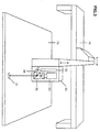
Embodiments of the laser scanners for laser spot scanning and laser spot sampling are
illustrated in FIG. 3 ∼ FIG. 6.
In FIG. 3, the laser projector of a laser scanner 30 includes a diode laser 32, a diode laser
mirror 34 and a diode laser beam splitter 36. The mirror 34 and the beam splitter 36 are
used to change the direction of the laser beam to be coaxial to a laser detector 33 to
correspondingly decrease the geometric distortion of the light spot 72. The laser scanner
30 is connected to a motorized linear positioning table 76 and moved horizontally and
vertically over the wood panel 70 to perform the laser spot scanning.
In FIGS. 4(a) to 4(c), the laser projector of a laser scanner 40 includes a diode laser 42, a
diode laser mirror 44 and a rotating polygon 46. The laser beam is reflected by the mirror
44 and scanned by the rotating polygon 46, producing the light spot 72 moving on the
surface of the wood panel 70 and sensed by a laser detector 43. The wood panel 70 is
travelling on the conveyor represented by rollers 78.
In FIGS. 5(a) to 5(c), the laser projector of a laser scanner 50 includes two diode lasers 52-1
and 52-2 with dot-matrix elements 58-1 and 58-2 attached. The laser projector generates
a low-density light spot-matrix 74 on the surface of the wood panel 70 for low-density laser
spot sampling. A laser detector 53 is in a low-rate scan mode for capturing the whole
image. The wood panel 70 is travelling on the conveyor represented by rollers 78.
In FIGS. 6(a) to 6(c), the laser projector of a laser scanner 60 includes seven diode lasers
62-1 to 62-7 with dot-matrix elements 68-1 to 68-7 attached. The laser projector generates
a high-density light spot-matrix 74 on the surface of the wood panel 70 for high-density
laser spot sampling. A laser detector 63 is in a high-rate scan mode for capturing a fourth
of the image. The wood panel 70 is travelling on the conveyor represented by rollers 78.
The hardware components of the above-described systems are all commercially available.
The diode laser 22, or any of the diode lasers 32 to 62, is capable of adjusting its laser
output and focal point. With a laser output control installed, the diode laser can change its
laser output according to an external laser control voltage. To give consideration to
adjusting the laser output linearly and enlarging the emergent laser spot, the diode laser is
preferably of 30 mW. With the capability of adjusting the focussing lens of the diode laser,
the laser spot size on a wood surface, which determines the resolution of the system 10, can
be changed from millimeters to centimeters.
While preferred embodiments of the present invention have been described, it will be
evident to those skilled in the art that further modifications of the illustrated embodiments
are possible without departing from the scope of the invention. For example, it is not
essential to install the function generator 81 to control the laser output. A computer I/O
board could alternatively be used to provide laser control voltage. Therefore, the scope of
the invention is not restricted to the particular embodiments that have been described, but
rather includes any modification falling within the following claims.