EP1193076B1 - Ink-jet recording apparatus with print head gap and pressing force adjustment - Google Patents
Ink-jet recording apparatus with print head gap and pressing force adjustment Download PDFInfo
- Publication number
- EP1193076B1 EP1193076B1 EP01123248A EP01123248A EP1193076B1 EP 1193076 B1 EP1193076 B1 EP 1193076B1 EP 01123248 A EP01123248 A EP 01123248A EP 01123248 A EP01123248 A EP 01123248A EP 1193076 B1 EP1193076 B1 EP 1193076B1
- Authority
- EP
- European Patent Office
- Prior art keywords
- paper
- pressing
- ink jet
- recording apparatus
- force adjustment
- Prior art date
- Legal status (The legal status is an assumption and is not a legal conclusion. Google has not performed a legal analysis and makes no representation as to the accuracy of the status listed.)
- Expired - Lifetime
Links
- 238000003825 pressing Methods 0.000 title claims abstract description 27
- 230000007246 mechanism Effects 0.000 claims description 25
- 230000002457 bidirectional effect Effects 0.000 abstract description 7
- 238000013461 design Methods 0.000 description 11
- 238000004519 manufacturing process Methods 0.000 description 11
- 230000006870 function Effects 0.000 description 9
- 230000005540 biological transmission Effects 0.000 description 6
- 238000000034 method Methods 0.000 description 5
- 230000008569 process Effects 0.000 description 5
- 238000012937 correction Methods 0.000 description 3
- 238000010586 diagram Methods 0.000 description 3
- 238000007599 discharging Methods 0.000 description 3
- 230000002452 interceptive effect Effects 0.000 description 2
- 239000000463 material Substances 0.000 description 2
- 230000004048 modification Effects 0.000 description 2
- 238000012986 modification Methods 0.000 description 2
- 230000035807 sensation Effects 0.000 description 2
- 230000001419 dependent effect Effects 0.000 description 1
- 239000013013 elastic material Substances 0.000 description 1
- 238000003780 insertion Methods 0.000 description 1
- 230000037431 insertion Effects 0.000 description 1
- 230000004044 response Effects 0.000 description 1
- 238000006467 substitution reaction Methods 0.000 description 1
Images


Classifications
-
- B—PERFORMING OPERATIONS; TRANSPORTING
- B41—PRINTING; LINING MACHINES; TYPEWRITERS; STAMPS
- B41J—TYPEWRITERS; SELECTIVE PRINTING MECHANISMS, i.e. MECHANISMS PRINTING OTHERWISE THAN FROM A FORME; CORRECTION OF TYPOGRAPHICAL ERRORS
- B41J25/00—Actions or mechanisms not otherwise provided for
- B41J25/304—Bodily-movable mechanisms for print heads or carriages movable towards or from paper surface
- B41J25/308—Bodily-movable mechanisms for print heads or carriages movable towards or from paper surface with print gap adjustment mechanisms
- B41J25/3082—Bodily-movable mechanisms for print heads or carriages movable towards or from paper surface with print gap adjustment mechanisms with print gap adjustment means on the print head carriage, e.g. for rotation around a guide bar or using a rotatable eccentric bearing
-
- B—PERFORMING OPERATIONS; TRANSPORTING
- B41—PRINTING; LINING MACHINES; TYPEWRITERS; STAMPS
- B41J—TYPEWRITERS; SELECTIVE PRINTING MECHANISMS, i.e. MECHANISMS PRINTING OTHERWISE THAN FROM A FORME; CORRECTION OF TYPOGRAPHICAL ERRORS
- B41J19/00—Character- or line-spacing mechanisms
- B41J19/14—Character- or line-spacing mechanisms with means for effecting line or character spacing in either direction
- B41J19/142—Character- or line-spacing mechanisms with means for effecting line or character spacing in either direction with a reciprocating print head printing in both directions across the paper width
- B41J19/145—Dot misalignment correction
-
- B—PERFORMING OPERATIONS; TRANSPORTING
- B41—PRINTING; LINING MACHINES; TYPEWRITERS; STAMPS
- B41J—TYPEWRITERS; SELECTIVE PRINTING MECHANISMS, i.e. MECHANISMS PRINTING OTHERWISE THAN FROM A FORME; CORRECTION OF TYPOGRAPHICAL ERRORS
- B41J25/00—Actions or mechanisms not otherwise provided for
- B41J25/304—Bodily-movable mechanisms for print heads or carriages movable towards or from paper surface
- B41J25/308—Bodily-movable mechanisms for print heads or carriages movable towards or from paper surface with print gap adjustment mechanisms
-
- B—PERFORMING OPERATIONS; TRANSPORTING
- B41—PRINTING; LINING MACHINES; TYPEWRITERS; STAMPS
- B41J—TYPEWRITERS; SELECTIVE PRINTING MECHANISMS, i.e. MECHANISMS PRINTING OTHERWISE THAN FROM A FORME; CORRECTION OF TYPOGRAPHICAL ERRORS
- B41J25/00—Actions or mechanisms not otherwise provided for
- B41J25/304—Bodily-movable mechanisms for print heads or carriages movable towards or from paper surface
- B41J25/312—Bodily-movable mechanisms for print heads or carriages movable towards or from paper surface with print pressure adjustment mechanisms, e.g. pressure-on-the paper mechanisms
Definitions
- the present invention relates to an ink jet recording apparatus that ejects ink droplets from a recording head toward a recording medium that is being fed by paper-feeding rollers and following rollers while being held between the rollers.
- An ink jet printer that is one of an ink jet recording apparatus, generally supplies a recording medium such as paper via an auto-sheet feeder (automatic successive sheet-feeding mechanism) or manually via a paper feed-in openings, and then feed the recording medium into a gap between a paper-feeding roller and a following roller. While the paper is transported by rotating the paper-feeding roller, a pressure is applied to ink in a pressure-generating chamber of a recording (printing) head so as to eject ink droplets toward the paper, thereby information is printed onto the paper.
- JP-A-63144063 shows a needle printer with combined paper gap and pressure adjustment. It is silent concerning the spatial relation of medium and printhead.
- the above ink jet printer can normally perform printing on both plain paper and thick paper.
- a distance defined between a paper surface and a plane on which nozzle openings are arranged i.e., a paper gap, is required to be always kept approximately constant by moving and adjusting the print head by means of a moving means for the print head.
- the plain paper has a thickness of about 0.6 mm or less, containing the variation, for example.
- the print head is controlled to move to adjust the paper gap to realize about 1.2 mm.
- the thick paper has a thickness of about 0.7 mm to 1.5 mm containing the thickness variation.
- a position of the print head for the thick paper is moved upward from the position for the plain paper by about 0.9 mm.
- an information recordable disk in which information can be personally recorded such as a CD-R, CD-RW, DVD-RAM or the like
- demands for personally printing a label on the printed disk have been increased.
- the label on the information recordable disk can be printed by supplying the information recordable disk with a tray made of extra-thick paper to the ink jet printer.
- the performances of the ink jet printers have been enhanced in recent years, so that some ink jet printers can perform a high accuracy full-color printing not only on plain paper and special-purpose paper but also on various types of thick paper.
- the conventional ink jet printer is designed, based on the assumption that the maximum thickness of paper handled by the ink jet printer is that of the thick paper, in such a manner that the thick paper manually fed in is allowed to press up against the following roller by its leading end and to be sandwiched between the paper-feeding roller and the following roller even if the following roller is pressed against the paper-feeding roller.
- the extra-thick paper used for the tray for fixing the information recordable disk has the thickness of about 1.6 mm to 2.5 mm.
- the pressing force F at the end of the extra-thick paper PPP works in a direction to rotate the following roller 1, as shown in Fig. 1 8 , failing to push up the following roller 1. Therefore, it is difficult to clamp the extra-thick paper PPP between the paper-feeding roller 2 and the following roller 1.
- the above problems can be solved by providing a release member for the following roller in the ink jet printer, which urges the following roller against the paper-feeding roller after the following roller has been released from the paper-feeding roller and then the extra-thick paper has been manually inserted into a space between the paper-feeding roller and the following roller.
- a release member for the following roller in the ink jet printer having such a release member, however, an operation lever for the moving means for the print head and an operation lever for the release member for the following roller are provided separately from each other.
- the mechanism becomes complicated and cannot be determined uniquely, and therefore the design of the mechanism also becomes complicated and the design error tends to occur.
- the thick paper has the thickness of about 0.7 mm to 1.5 mm, as described above. This means the thickness of the thick paper has variation of about 0.8 mm. Moreover, in a case of extra-thick paper for printing CD-R or the like, the thickness is in the range of about 1.6 mm to 2.5 mm. Thus, the variation range of the thickness reaches about 0.9 mm. As described above, the thickness of the thick paper or the extra-thick paper changes depending on the type of paper, thus causing large differences of the paper gap between the types of paper.
- an ink jet recording apparatus having a feed roller and a following roller operable to interpose recording medium and to feed the recording medium, and a recording head operable to eject ink droplets onto the recording medium
- the apparatus comprises: a paper gap switching portion operable to switch paper gaps by moving the recording head; wherein said recording head remains substantially parallel to said recording medium as said paper gap is changed; a pressing-force adjustment portion operable to apply a pressure to the following roller or release the pressure to adjust a pressing force applied to the recording medium; and an operation member operable to operate in series two series of driving operations including a driving operation of the paper gap switching portion and a driving operation of the pressing-force adjustment portion.
- the paper gap switching portion and the pressing-force adjustment portion can be operated by the operation of the operation member only, it is possible to smoothly perform the switching of the paper gaps and the adjustment of the pressing force without fail, improving the user's operability.
- the functions of switching the paper gaps and adjusting the pressing force are integrated with the function of operating those functions, the structures of the operation member, the paper gap switching portion and the pressing-force adjustment portion can be made simple, so that the design can be simplified and, therefore, the design error can be reduced.
- the cost for the manufacture and assembly and the number of the processes of the manufacture and assembly can be reduced.
- the operation member may include an intermittent gear operable to switch and transmit the two series of-driving operations.
- the operation member, the pressing-force adjustment portion and the paper gap switching portion may be formed by a gear mechanism and a link mechanism.
- the operation member, the paper gap switching portion and the pressing-force adjustment portion can be formed by components having a relatively simple structure, the manufacturing cost can be reduced.
- the operation member may include a first intermittent gear having an operation lever, a second intermittent gear arranged to be engageable with the first intermittent gear, and a third intermittent gear arranged to have the same rotation axis as the second intermittent gear;
- the pressing-force adjustment portion may include a fourth intermittent gear arranged to be engageable with the second intermittent gear and to have a shaft in which a part of a circumference is formed to be a flat surface, a fifth intermittent gear arranged to be engageable with the third intermittent gear, a following roller arm having one end onto which the following roller is rotatably mounted and another end rotatably attached to the shaft of the fourth intermittent gear, and a coil spring having an end fixed to the following roller, another end that is in contact with the shaft of the fourth intermittent gear and a center part fitted to approximately at a center of the following roller arm; and the paper gap switching portion may include a first link fitted to a shaft of the fifth intermittent gear at its one end, a second link hinged at its one end to another end of the first link, a third link hinge
- the operation member, the paper gap switching portion and the pressing-force adjustment portion can be formed by components having a relatively simple structure, the manufacturing cost can be reduced. Moreover, since the switching of the two series of driving operations can be mechanically realized by simple components, the switching operations can be performed with high accuracy without fail.
- the ink jet recording apparatus may further include a click mechanism, formed integrally with the operation lever, operable to position the operation lever when the pressing force adjustment portion applies the pressure and when the pressing force adjustment portion release the pressure.
- a click mechanism formed integrally with the operation lever, operable to position the operation lever when the pressing force adjustment portion applies the pressure and when the pressing force adjustment portion release the pressure.
- a position of the operation lever when the pressing-force adjustment portion applies the pressure may be arranged to be apart from a further position of the operation lever when the pressing-force adjustment portion releases the pressure.
- the second link and the forth link may be arranged on the same side of the body of the recording apparatus.
- the operation of the second link can be transmitted directly to the fourth link, it is possible to prevent the transmission failure caused by an unstable connection between the second and fourth links in a case where the second and fourth links are arranged on both side of the body, respectively.
- the maximum one of the paper gaps is provided when the pressing-force adjustment portion release the pressure.
- an ink jet recording apparatus having a feeding roller and a following roller operable to feed a recording medium while interposing the recording medium, and a recording head operable to eject ink droplets on the recording medium
- the apparatus includes: a paper gap switching portion operable to switch a first paper gap and a second paper gap by moving the print head, the second paper gap being larger than the first paper gap; wherein said recording head remains substantially parallel to said recording medium as said paper gap is changed; and a pressing-force adjustment portion operable to apply a pressure to the following roller or release the pressure to adjust a pressing force applied to the recording medium, wherein three states are switched by a single operation lever, the three states including a state where the first paper gap is set and the pressure is applied, another state where the second paper gap is set and the pressure is applied, and still another state where the pressure is released.
- the paper gap switching portion and the pressing-force adjustment portion can be operated by the operation of the operation member only, it is possible to smoothly perform the switching of the paper gaps and the adjustment of the pressing force without fail, improving the user's operability.
- the functions of switching the paper gaps and adjusting the pressing force are integrated with the function of operating those functions, the structures of the operation member, the paper gap switching portion and the pressing-force adjustment portion can be made simple, so that the design can be simplified. Therefore, the design error can be reduced, and the cost for the manufacture and assembly and the number of the processes of the manufacture and assembly can be reduced.
- Switching positions of the operation lever for switching the three states may be arranged in series.
- the operations of the operation lever can be performed in series, so that the printing setting can be performed more quickly.
- Operations at the switching positions may be arranged in an order of setting the first paper gap and applying the pressure, setting the second paper gap and applying the pressure, and releasing the pressure.
- the operations are arranged in an order of the printing for plain paper having a normal thickness, the printing for thick paper thicker than the plain paper, insertion/discharge of the paper, and various types of printing can be performed more quickly.
- the paper gap switching portion and the pressing-force adjustment portion may be formed by a gear mechanism and a link mechanism.
- the operation member, the paper gap switching portion and the pressing-force adjustment portion can be formed by components having a relatively simple structure, the manufacturing cost can be reduced.
- the pressure applied by the pressing-force adjustment portion maybe applied by an elastic member.
- the application and the release of the pressing force canbe performed simply without fail.
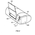
- Figs. 1 and 2 are perspective views of an ink jet printer as an exemplary ink jet recording apparatus according to an embodiment of the present invention, seen from a front side and a rear side, respectively.
- the ink jet printer includes a recording (print) head 100, a head driving section (not shown), an auto sheet feeder (automatic successive feeding section, not shown), a paper gap switching portion/pressing-force adjustment portion 200 that are provided in a body 101.
- a paper discharging opening 102 On the front side of the body 101 is provided a paper discharging opening 102.
- On the rear side of the body 101 is provided a paper feeding-in opening 103.
- a tray 104 for the auto sheet feeder is provided above the paper feeding-in opening 103 on the rear side of the body 101.
- an operation lever 201 that serves as an operation portion 200C ( Fig. 3 ) of the paper gap switching portion/pressing-force adjustment portion 200 is provided to project from the body 101.
- the print head 100 includes, for example, four color ink cartridges 105 including yellow, magenta, cyan and black ink cartridges and is arranged to allow full-color printing to be performed. Timings of ejecting ink droplets from the print head 100 and scan of the print head 100 by the head driving section are controlled by an exclusive controller board or the like, that is incorporated in the body 101, thereby realizing ink-dot control with high accuracy, half-tone process and the like.
- Recording paper placed on the tray 104 is automatically fed by the auto sheet feeder to a space between a paper-feeding roller and a following roller (both not shown) and is further transported by the rollers while being sandwiched between the rollers. Finally, the paper is discharged via the paper discharging opening 102. Recording paper manually fed into the paper feeding-in opening 103 is similarly transported by the paper-feeding roller and the following roller while being sandwiched between the rollers, and is then discharged via the paper discharging opening 102.
- the recording paper fed from the tray 104 plain paper, special paper, recommended OHP sheet, coated paper, coated film, label sheet, official postcards and the like can be used.
- the recording paper manually fed via the paper feeding-in opening 103 the above-mentioned types of paper, film and card, and thick material including thick paper and extra-thick paper (including a tray for an information recordable disk), that is, the material difficult to be folded can be used.
- the operation lever 201 serving as the operation member 200C is arranged to be slidable along a slit 110 provided on the body 101 like a straight line along direction a, shown with double headed arrow in Fig. 2 , in a step-like manner so as to set the paper gap switching portion/pressing-force adjustment portion 200.
- the paper gap switching portion is arranged to move and adjust the print head 100 so as to make the distance between the paper surface and a plane of nozzle openings of the print head 100, that is, the paper gap, approximately constant, in order to keep the printing precision high and approximately constant regardless of the thickness of the recording paper.
- the pressing-force adjustment portion is arranged to press the following roller against the paper-feeding roller by applying pressure to the following roller in order to sandwich the recording paper between the rollers, or to release the following roller from the paper-feeding roller by releasing the above pressure in order to pull the recording paper out from the space between the rollers.
- Fig. 3 is a block diagram illustrating a relationship among the operation member 200C, a paper gap switching portion 200A and a pressing-force adjustment portion 200B in the paper gap switching /pressing-force adjustment portion 200.
- the operation member 200C is provided in mechanical association with each of the paper gap switching portion 200A and the pressing-force adjustment portion 200B.
- the paper gap switching portion 200A and the pressing-force adjustment portion 200B can be operated, so as to place the print head 100 and the following roller 202 in a desired state.
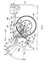
- Fig. 4 is a cross-sectional view of the printer, seen from the side thereof, and illustrates a detailed example of the paper gap switching portion 200A and the pressing-force adjustment portion 200B.
- the operation member 200C includes a first intermittent gear 211 towhich the operation lever 201 is integrally formed, and second and third intermittent gears 212 and 214.
- the paper gap switching portion 200A includes first, second, third, fourth and fifth links 231, 232, 233, 234, and 235 and an eccentric cam 236 to which the print head is attached.
- the pressing-force adjustment portion 200B includes a fourth intermittent gear 213 having a shaft 213a in which a part of a circumference is formed to be flat, a fifth intermittent gear 215, a following roller arm 204 with the following roller 202 rotatably mounted at its one end, and a coil spring 205.
- the operation lever 201 is integrally formed with the first intermittent gear 211 so as to project from the circumferential part of the first intermittent gear 211, and can pivotally reciprocate in direction a, shown with double-headed arrow in Fig. 4 .
- a wave-like ratchet tooth 221 serving as a click mechanism 220 is formed integrally with the gear 211. Depressions of the wave-like ratchet tooth 221 are formed to correspond to positions A, B, C and D at which the operation lever 201 pivotally moved to be positioned.
- a ratchet 222 of the click mechanism 220 is pressed against the ratchet tooth 221 by a coil spring 223.
- the ratchet 222 fits into the corresponding depression of the wave-like ratchet tooth 221. Therefore, the user can recognize by excellent touch of click that the operation lever 201 is positioned at the desired position without fail. If the operation lever 201 and the ratchet tooth 221 are formed as separate components, the touch of the click is not good because the touch is transmitted via the shaft 211a of the first intermittent gear 211. In this example, however, the touch of the click can be transmitted directly since the operation lever 201 is integrally formed with the ratchet gear 221, thus enabling the user to recognize that the operation lever 201 is positioned at the respective position without fail.
- positions A, B, C and D are briefly explained.
- the operation lever 201 When the operation lever 201 is positioned at position A, the recording paper having a normal thickness, that is, plain paper is used.
- the operation lever 202 When the operation lever 202 is positioned at position B, slightly thicker recording paper than the plain paper, that is, thick paper is used.
- the operation lever 202 When the operation lever 202 is positioned at position C, very thick recording paper which is extra-thick paper containing a tray for information recordable disk is used.
- the operation lever 201 When the operation lever 201 is positioned at position D, the following roller 202 is released from the paper-feeding roller 203.
- Positions A, B and C for the adjustment of the paper gap are arranged in such a manner that they are relatively close to each other.
- Position D at which the following roller 202 is released from the paper-feeding roller 203 by the operation lever 201 is arranged to be away from respective positions A, B and C by predetermined distances.
- the first intermittent gear 211 is arranged to be engagable with the second intermittent gear 212, which is arranged to be engagable with the fourth intermittent gear 213.
- the third intermittent gear 214 which is arranged to have the same axis as the second intermittent gear 212, is arranged to be engagable with the fifth intermittent gear 215.
- the shaft 213a of the fourth intermittent gear 213 is a so-called D-shaft in which the circumferential surface thereof is formed to be flat.
- an end of the following roller arm 204 is rotatably connected with the following roller 202 rotatably mounted on another end thereof.
- the center part of the coil spring 205 having an end fixed to the following roller 202 and another end that is in contact with the D-shaft 213a is fixed.
- a free end of the first link 231 hinged to the second link 232 to form a substantially L-shape by a hinge 231a is fitted.
- a free end of the second link 232 is hinged to an end of the third link 233 by a hinge 232a that is closer to the hinge 233a than another end of the third link 223.
- the third, fourth and fifth links 233, 234 and 235 are jointed by the hinges 233a and 234a to form an approximately U-shape.
- a free end of the third link 233 is connected to the print head 100 via the eccentric cam 236.
- a free end of the fifth link 235 is rotatably supported by the body 101 with a shaft.
- the fourth link 234 is arranged on the right side of the body 101, and the second link 232 and the fourth link 234 are connected by a new link mechanism, for example, an extra space is generated on the left side of the body 101, thereby increasing the freedom of the design.
- loss of transmission of the operation of second link 232 to the fourth link 234 may result or the transmission may fail, since the transmission takes place via the new link mechanism.
- the second and fourth links 232 and 234 are arranged on the same side of the body 101, i.e., the left side of the body 101 when the printer is seen from the front side.
- the operation of the second link 232 can be transmitted directly to the fourth link 234 without fail, so that the transmission loss or the fail of transmission can be prevented.
- limit switches 241 and 242 are provided below the first intermittent gear 211.
- the limit switch 241 is provided for turning on/off the auto sheet feeder by rotation of the first intermittent gear 211.
- the other limit switch 242 is provided for turning on/off the printer.
- an encoder 243 is mounted to the paper-feeding roller 203, which encoder is used for controlling the paper-feeding roller 203 in the printing on the recording paper. More specifically, the encoder 243 is mounted on a rotor shaft of the paper-feeding roller 2 03 and rotates together with a paper-feeding motor for driving the paper-feeding roller 203. In the present embodiment, a DC motor is employed as the paper-feeding motor for the purpose of reducing noise from the motor.
- the encoder 243 generates electric pulse signals while rotating with the paper-feeding motor 203, and the pulse signals are counted to measure the rotation amount of the encoder 243, so that paper feeding amount by the paper-feeding roller 203 can be measured.
- the operation member 200C is provided for operating in series two series of driving operations including the driving of the paper gap switching portion 200A and the driving the pressing-force adjustment portion 200B, the switching of the paper gaps and the adjustment of the pressing force can be performed by the operation of the operation member 200C only. Therefore, it is possible to smoothly perform the switching of the paper gaps and the pressing-force adjustment without fail, improving the user's operability.
- the structures of the operation member 200C, the paper gap switching portion 200A and the pressing-force adjusting portion 200B can be simplified.
- the designs thereof are also simplified, thereby reducing the design error, the cost of fabrication and assembly, and the number of processes of the fabrication and assembly.
- the print head 100 is moved and adjusted to realize the paper gap ha of about 1.2 mm, for example, because the typical thickness of the plain paper containing the variation is about 0.6 mm or less.
- Both the limit switches 241 and 242 in this state are turned on, and lamps 106 and 107 provided on the front side of the body 101, shown in Fig. 1 , are lighted.
- the fourth intermittent gear 214 is first rotated together with the second intermittent gear 212 in direction c1 by rotation of the first intermittent gear 211 in direction b1. Furthermore, the fifth intermittent gear 215 is rotated in direction d1. Therefore, the respective links 231 to 235 as a whole rotate in direction e1, so that the print head 100 is moved in direction f1, that is, upward, as shown in Fig. 7 .
- the third intermittent gear213 starts to rotate in direction g1, as shown in Fig. 6 .
- the coil spring 205 is brought into contact with the flat portion of the D-shaft 213a, so that the following roller 202 is released from the elasticity of the coil spring 205 and is therefore released from the paper-feeding roller 203 in direction m1.
- both the limit switches 241 and 242 are turned off, and the lamps 106 and 107 provided on the front-side of the body 101 as shown in Fig. 1 go on and off.
- the print head 100 is moved to a place at a position away from the position of the print head 100 for plain paper, shown in Fig. 5 , by about 1.2 mm, since the thickness of the thick paper containing the variation is in the range of about 0.7 mm to 1.5 mm, for example.
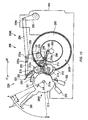
- the third intermittent gear 213 rotates in direction g2, as shown in Fig. 8 , and the coil spring 205 is pressed by the D-shaft 213a, as shown in Fig. 9 .
- the elasticity of the coil spring 205 is applied to the following roller 202 in such a manner that the following roller is moved in a rotating manner in direction m2 to press the thick paper PP that has been transported into the space between the rollers 202 and 203 against the paper-feeding roller 203.
- the limit switch 241 is turned off while the other limit switch 242 is turned on.
- the lamp 106 provided on the front side of the body 101, as shown in Fig. 1 goes on and off, while the lamp 107 is lighted.
- a main controlling unit of the printer receives an ON-signal issued by the limit switch 242 and performs control of the printing.
- the print head 100 is moved to place at a position away from the position of the print head 100 for the plain paper shown in Fig. 5 by about 2.5 mm, because the thickness of the extra-thick paper containing variation is in the range of about 1.6 mm to 2.5 mm.
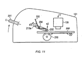
- the third intermittent gear 213 rotates in direction g2, as shown in Fig. 10 , so that the coil spring 205 is pressed by the D-shaft 213a, as shown in Fig. 11 .
- the elasticity of the coil spring 205 that is pressed by the D-shaft 213a is applied to the following roller 202 in such a manner that the following roller 202 is rotated in direction d2 to press the extra-thick paper PPP that was transported to the space between the rollers 202 and 203.
- the limit switch 241 is turned off, while the limit switch 242 is turned on.
- the lamp 106 provided on the front side of the body 101 goes on and off, while the other lamp 107 is lighted.
- the system After the lamp 107 is lighted, the system performs the similar control to that when the operation lever 201 is positioned at position B.
- Fig. 12 is a cross-sectional view of the printer illustrating another example of the paper gap switching portion/pressing-force adjustment portion 200 in detail.
- the paper gap switching portion/pressing-force adjustment portion 200 shown in Fig. 12 has the same components as that shown in Fig. 4 , but parts of the components of the pressing-force adjustment portion 200B are arranged in a different manner from that shown in Fig. 4 .
- Fig. 12 shows parts of the operation member 200C and the pressing-force adjustment portion 200B and the print head 100 only. The remaining parts of the operation member 200C and the pressing-forceadjustmentportion200B, and the paper gap switching portion 200A are omitted in Fig. 12 .
- the same components are labeled with the same reference numerals or signs in Figs. 4 and 15 .
- the pressing-force adjustment portion 200B shown in Fig. 12 includes the fourth intermittent gear (not shown) having the shaft 213a in which part of a circumferential part is formed to be flat, the fifth intermittent gear (not shown), the following roller arm 204 with the following roller 202 rotatably mounted onto its one end, and the coil spring 205.
- Those components are respectively the same as the corresponding components of the pressing-force adjustment portion 200B shown in Fig. 4 , but are arranged in a different manner as follows.
- the shaft 213a presses one end of the coil spring 205 by its rotation, so that the other end of the coil spring 205 presses the following roller 202 mounted onto one end of the following roller arm 204 against the paper-feeding roller 203. Then, the shaft 213a further rotates, so that the pressure applied to the end of the coil spring 205 is released. Thus, the pressure applied to the other end of the coil spring 205 is also released, thereby releasing the following roller 202 from the paper-feeding roller 203.
- one end of the coil spring 205 is fixed to a frame 108 of the body in advance, while the other end of the coil spring 205 presses the following roller 202 mounted on one end of the following roller arm 204 against the paper-feeding roller 203 by resilient force of the coil spring 205. Then, the other end of the following roller arm 204 is pressed by the rotation of the shaft 213a, so that the following roller 202 moves the other end of the coil spring 205 upwards to be released from the paper-feeding roller 203.
- the operation member 200C includes the first intermittent gear 211 having the operation lever 201, and the second and third intermittent gears (both not shown). These components of the operation member 200C are the same as the corresponding ones in Fig. 4 , and the arrangement of the components of the operation member 200C is also the same as that of the components in Fig. 4 .
- the operation lever 201 is integrally formed with the first intermittent gear 211 so as to project from the circumferential part of the first intermittent gear 211, and can rotate in a reciprocating manner around the shaft 211a of the first intermittent gear 211 in direction a shown with arrow in Fig. 12 .
- a wave-like ratchet tooth 221 serving as a click mechanism 220 is formed integrally with the gear 211.
- Depressions of the wave-like ratchet tooth 221 are formed to correspond to positions A, B, C and D at which the operation lever 201 pivotally moved to be positioned. Moreover, a ratchet 222 of the click mechanism 220 is pressed against the ratchet tooth 221 by the coil spring 223.
- the ratchet 222 fits into the corresponding depression of the wave-like ratchet tooth 221, like the operation member 200C shown in Fig. 4 . Therefore, the user can recognize by excellent touch of click that the operation lever 201 is positioned at the desired one of the positions A, B, C and D without fail.
- Positions A, B and C of the operation lever 201 for the adjustment of the paper gaps are arranged in such a manner that they are relatively close to each other.
- Position D of the operation lever 201 at which the following roller 202 is released from the paper-feeding roller 203 is arranged to be apart from Positions A, Band C by predetermined distances, respectively.
- Figs. 12 to 15 the operations of the above-mentioned components are described referring to Figs. 12 to 15 .
- resilience of the coil spring 205 is applied to the following roller 202 so as to press plain paper P transported into the space between the paper-feeding roller 203 and the following roller 202.
- the print head 100 is moved to provide the paper gap ha that corresponds to the plain paper P.
- the print head 100 is moved and adjusted to realize the paper gap ha of about 1.2 mm, for example, because the typical thickness of the plain paper containing the variation is about 0.6 mm or less.
- Both the limit switches 241 and 242 in this state are turned on, and the lamps 106 and 107 provided on the front side of the body 101, shown in Fig. 1 , are lighted.
- the operation lever 201 When the operation lever 201 is moved from position A and is then positioned at position D, as shown in Fig. 13 , the following roller 202 is released from the paper-feeding roller 203 in direction m1, and the print head 100 also moves upward in direction f1 to provide the maximum paper gap. Therefore, in this state, even the extra-thick paper, the tray for the information recordable disk or the like can be transported smoothly through the respective spaces between the components without interfering with the following roller 202 and the print head 100.
- the print head 100 is moved in direction f2, that is, downward, by rotation of the first intermittent gear 211.
- the print head 100 is placed at a position away from the position of the print head 100 for plain paper, shown in Fig. 10 , by about 1.2 mm, since the thickness of the thick paper including variation is in the range of about 0.7 mm to 1.5 mm, for example.
- the following roller arm 204 is pressed down by resilience of the coil spring 205 since the other end of the following roller arm 204 is brought into contact with the flat portion of the D-shaft 213a.
- the following roller 202 presses the thick paper PP that has been transported into the space between the rollers 202 and 203 against the paper-feeding roller 203.
- the limit switch 241 is turned off while the other limit switch 242 is turned on.
- the lamp 106 provided on the front side of the body 101 as shown in Fig. 1 goes on and off, while the lamp 107 is lighted.
- the print head 100 In a state shown in Fig. 15 , in which the operation lever 201 is moved from position D to be positioned at position C, the print head 100 is moved in direction f2, that is, downward, by rotation of the first intermittent gear 211. In this state, the print head 100 is moved to place at a position away from the position for plain paper shown in Fig. 12 by about 2.5 mm, because the thickness of the extra-thick paper is in the range of about 1.6 mm to 2.5 mm, considering the thickness variation.
- the paper gap switching portion 200A for moving the print head 100 so as to switch the different paper gaps and the pressing-force adjustment portion 200B for applying the pressure to the following roller 202 or releasing the applied pressure so as to adjust the pressing force applied to sheets of printing paper having different thicknesses are provided.
- two series of operations, i.e., the switching and adjustment operations for the paper gap switching portion 200A and the pressing-force adjustment portion 200B can be mechanically performed by components having simple structures, i.e., the second and third intermittent gear 212 and 214 that are connected to the single operation lever 201 serving as the operation member 200C.
- the switching/adjustment operations with high accuracy without fail.
- the switching of the paper gaps for the print head 100 by the paper gap switching portion 200A can be performed via the second and third intermittent gears 212 and 214.
- the switching between the pressure application to the following roller 202 and the pressure release from the following roller 202 can be smoothly performed in the step-like manner by operating the operation lever 201 via the second and third gears 212 and 214.
- the operation member 200C, the paper gap switching portion 200A and the pressing-force adjustment portion 200B are formed by a gear mechanism and a link mechanism, they can be implemented by simple mechanisms.
- the present invention is described in the above referring to various embodiments, the present invention is not limited to the above embodiments, but other embodiments within the scope of the invention defined by the claims can be considered.
- the second and third intermittent gears 212 and 214 used for switching the two series of the driving operations for the paper gap switching portion 200A and the pressing-force adjustment portion 200B may be jointed with each other to have the same rotation axis, after being fabricated as separate parts. Alternatively, they may be integrally fabricated.
- a case was described where four switching positions of the operation lever 201 are set, that include position A for plain paper that is recording paper having a typical thickness; position B for thick paper that is slightly thicker than the plain paper; position C for extra-thick paper, including the tray for the information recordable disk, that is considerably thicker than the plain paper; and position D at which the following roller 202 is released from the paper-feeding roller 203 .
- the switching positions of the operation lever 201 are not limited to the above case.
- the present invention can be applied to the printer, as long as at least three positions including position P that provides the first head gap, position Q that provides the second head gap larger than at least the first head gap, and position R at which the following roller 202 is released from the paper-feeding roller 203 are set.
- positions A, B, C and D were arranged in that order.
- the present invention can be applied to a case where the switching positions are arranged in an arbitrary order.
- positions P, Q and R may be arranged in an order of P, Q and R, in another order of R, P and Q and in still another order of P, R and Q.
- positions P and Q may be arranged on a slit 310 that is a C-shaped groove formed on the body 101 of the ink jet printer, in such a manner that one of positions P and Q is set to an upper position than the other.
- Position R is provided at one side of each of positions P and Q, as shown in Fig. 16 . In this case, the switching to the release of the following roller 202 from the paper-feeding roller 203 canbe performed more quickly.
- the following roller 202 is actually released from the paper-feeding roller 203.
- Any structure can be adopted as long as the pressing force applied to the printing paper is released.
- the pressing force to the following roller 202 can be released.
- the following roller 202 is brought into contact with the paper-feeding roller 203 by the weight thereof. Then, when the D-shaft 313a rotates to press the coil spring 305, the pressing force can be applied to the following roller 202.
- the member of the pressing-force adjustment portion 200B for pressing the following roller 202 is not limited to the coil spring 205 or 305. Any member formed of elastic material such as rubber can be used. Moreover, when the D-shaft 213a is formed in fan shape, an angle range for the operation of the operation lever201canbemadewider. Inaddition, although the intermittent gears 214 and 215 are used in order to reduce the moving distance of the print head 100, typical gear gears can be used in place of intermittent gears in a case where there is no limit to the moving distance of the print head 100. In this case, the cost for the parts and components can be reduced.
- the limit switch 242 is arranged to turn on by positioning the operation lever 201 at the position for the thick paper or the extra-thick paper, so as to issue the ON-signal, thereby prohibiting the bidirectional printing.
- the control of prohibiting the bidirectional printing may be performed in response to a signal issued from a sensor or the like which electrically or optically detects that the thick paper or the extra-thick paper is manually inserted into the paper feeding-in opening 103.
- the printer is described as the ink jet recording apparatus in the above embodiments, the ink jet recording apparatus is not limited thereto.
- the present invention can be applied to other ink jet recording apparatus, such as a facsimile apparatus or a copy apparatus, as long as it includes a feeding mechanism for the recording medium.
- the paper gap switching portion and the pressing-force adjustment portion can be operated only by the operation of the operation member.
- the switching of the paper gaps and the adjustment of the pressing force can be smoothly performed without fail, improving the operability of the user.
- the structures of the operation member, the paper gap switching portion and the pressing force adjustment portion become simple, the design of those mechanisms becomes easier and therefore the design error can be reduced. Also, the cost for the fabrication and assembly and the number of processes in the fabrication and assembly can be reduced.
- the ink jet recording apparatus of the present invention even in a case where relatively thick paper is used and therefore the paper gap becomes large, the shifts of the dot-positions between two directions in the bidirectional printing cannot occur, thus preventing the printing quality from being degraded.
- the thickness of the paper is largely varied depending on the type of the thick paper, the stable printing quality can be achieved.
- the bidirectional printing can be automatically prohibited only by operating the single operation lever 201 to position at the position for the thick paper or the position for the extra-thick paper.
Landscapes
- Ink Jet (AREA)
- Handling Of Sheets (AREA)
- Common Mechanisms (AREA)
- Delivering By Means Of Belts And Rollers (AREA)
- Particle Formation And Scattering Control In Inkjet Printers (AREA)
- Luminescent Compositions (AREA)
- Handling Of Cut Paper (AREA)
Abstract
Description
- The present invention relates to an ink jet recording apparatus that ejects ink droplets from a recording head toward a recording medium that is being fed by paper-feeding rollers and following rollers while being held between the rollers.
- An ink jet printer, that is one of an ink jet recording apparatus, generally supplies a recording medium such as paper via an auto-sheet feeder (automatic successive sheet-feeding mechanism) or manually via a paper feed-in openings, and then feed the recording medium into a gap between a paper-feeding roller and a following roller. While the paper is transported by rotating the paper-feeding roller, a pressure is applied to ink in a pressure-generating chamber of a recording (printing) head so as to eject ink droplets toward the paper, thereby information is printed onto the paper.
JP-A-63144063 - The above ink jet printer can normally perform printing on both plain paper and thick paper. In order to keep a printing quality high and substantially constant, a distance defined between a paper surface and a plane on which nozzle openings are arranged, i.e., a paper gap, is required to be always kept approximately constant by moving and adjusting the print head by means of a moving means for the print head.
- The plain paper has a thickness of about 0.6 mm or less, containing the variation, for example. In this case, the print head is controlled to move to adjust the paper gap to realize about 1.2 mm. On the other hand, the thick paper has a thickness of about 0.7 mm to 1.5 mm containing the thickness variation. Thus, a position of the print head for the thick paper is moved upward from the position for the plain paper by about 0.9 mm.
- Moreover, an information recordable disk in which information can be personally recorded, such as a CD-R, CD-RW, DVD-RAM or the like, has been becoming popular in recent years. Also, demands for personally printing a label on the printed disk have been increased. In this case, the label on the information recordable disk can be printed by supplying the information recordable disk with a tray made of extra-thick paper to the ink jet printer. Further, the performances of the ink jet printers have been enhanced in recent years, so that some ink jet printers can perform a high accuracy full-color printing not only on plain paper and special-purpose paper but also on various types of thick paper.
- The conventional ink jet printer is designed, based on the assumption that the maximum thickness of paper handled by the ink jet printer is that of the thick paper, in such a manner that the thick paper manually fed in is allowed to press up against the following roller by its leading end and to be sandwiched between the paper-feeding roller and the following roller even if the following roller is pressed against the paper-feeding roller.
- The extra-thick paper used for the tray for fixing the information recordable disk, however, has the thickness of about 1.6 mm to 2.5 mm. Thus, if the extra-thick paper is manually fed in and presses up against the following roller by its leading end, the pressing force F at the end of the extra-thick paper PPP works in a direction to rotate the following
roller 1, as shown inFig. 1 8 , failing to push up the followingroller 1. Therefore, it is difficult to clamp the extra-thick paper PPP between the paper-feeding roller 2 and the followingroller 1. - The above problems can be solved by providing a release member for the following roller in the ink jet printer, which urges the following roller against the paper-feeding roller after the following roller has been released from the paper-feeding roller and then the extra-thick paper has been manually inserted into a space between the paper-feeding roller and the following roller. In a conventional ink jet printer having such a release member, however, an operation lever for the moving means for the print head and an operation lever for the release member for the following roller are provided separately from each other. Thus, the mechanism becomes complicated and cannot be determined uniquely, and therefore the design of the mechanism also becomes complicated and the design error tends to occur.
- Moreover, the thick paper has the thickness of about 0.7 mm to 1.5 mm, as described above. This means the thickness of the thick paper has variation of about 0.8 mm. Moreover, in a case of extra-thick paper for printing CD-R or the like, the thickness is in the range of about 1.6 mm to 2.5 mm. Thus, the variation range of the thickness reaches about 0.9 mm. As described above, the thickness of the thick paper or the extra-thick paper changes depending on the type of paper, thus causing large differences of the paper gap between the types of paper.
- Therefore, when relatively thin thick-paper is used, the paper gap becomes large and the shifts of dot-printing positions between the two directions in the bidirectional printing also become large. This may cause the printing quality to be degraded. There are some printers that can correct the positional shifts with a constant rate in the bidirectional printing. Such correction, however, is performed based on the assumption that the paper gap is constant. Thus, when the paper thickness changes depending on the type of the thick paper, stable printing quality cannot be achieved. Moreover, if a correction value in the above correction is changed to be several values depending on the type of the thick paper, causing control of the printing to be extremely complicated.
- Therefore, it is an obj ect of the present invention to provide an ink jet recording apparatus, which is capable of overcoming the above drawbacks accompanying the conventional art. More specifically, it is an object of the present invention to provide an ink jet recording apparatus that can uniquely adjust a recording head and a following roller simply. Further, it is another object of the present invention to provide an ink jet recording apparatus that can perform high accuracy printing with stable printing quality on any type or thickness of thick paper. The above and other objects can be achieved by combinations described in the independent claims. The dependent claims define further advantageous and exemplary combinations of the present invention.
- According to the first aspect of the present invention, an ink jet recording apparatus having a feed roller and a following roller operable to interpose recording medium and to feed the recording medium, and a recording head operable to eject ink droplets onto the recording medium, the apparatus comprises: a paper gap switching portion operable to switch paper gaps by moving the recording head; wherein said recording head remains substantially parallel to said recording medium as said paper gap is changed; a pressing-force adjustment portion operable to apply a pressure to the following roller or release the pressure to adjust a pressing force applied to the recording medium; and an operation member operable to operate in series two series of driving operations including a driving operation of the paper gap switching portion and a driving operation of the pressing-force adjustment portion.
- Thus, since the paper gap switching portion and the pressing-force adjustment portion can be operated by the operation of the operation member only, it is possible to smoothly perform the switching of the paper gaps and the adjustment of the pressing force without fail, improving the user's operability. Moreover, since the functions of switching the paper gaps and adjusting the pressing force are integrated with the function of operating those functions, the structures of the operation member, the paper gap switching portion and the pressing-force adjustment portion can be made simple, so that the design can be simplified and, therefore, the design error can be reduced. In addition, the cost for the manufacture and assembly and the number of the processes of the manufacture and assembly can be reduced.
- The operation member may include an intermittent gear operable to switch and transmit the two series of-driving operations. Thus, the switching of the two series of driving operations can be mechanically realized by simple components and therefore the switching operations can be performed with high accuracy without fail.
- The operation member, the pressing-force adjustment portion and the paper gap switching portion may be formed by a gear mechanism and a link mechanism. Thus, since the operation member, the paper gap switching portion and the pressing-force adjustment portion can be formed by components having a relatively simple structure, the manufacturing cost can be reduced.
- The operation member may include a first intermittent gear having an operation lever, a second intermittent gear arranged to be engageable with the first intermittent gear, and a third intermittent gear arranged to have the same rotation axis as the second intermittent gear; the pressing-force adjustment portion may include a fourth intermittent gear arranged to be engageable with the second intermittent gear and to have a shaft in which a part of a circumference is formed to be a flat surface, a fifth intermittent gear arranged to be engageable with the third intermittent gear, a following roller arm having one end onto which the following roller is rotatably mounted and another end rotatably attached to the shaft of the fourth intermittent gear, and a coil spring having an end fixed to the following roller, another end that is in contact with the shaft of the fourth intermittent gear and a center part fitted to approximately at a center of the following roller arm; and the paper gap switching portion may include a first link fitted to a shaft of the fifth intermittent gear at its one end, a second link hinged at its one end to another end of the first link, a third link hinged at its one end to another end of the second link, a fourth link hinged at its one end to the one end of the third link, a fifth link hinged at its one end to another end of the fourth link, and an eccentric cam, to which the recording head is attached, connected to another end of the third link, the fifth link being supported at its another end by a body of the ink jet recording apparatus.
- Thus, since the operation member, the paper gap switching portion and the pressing-force adjustment portion can be formed by components having a relatively simple structure, the manufacturing cost can be reduced. Moreover, since the switching of the two series of driving operations can be mechanically realized by simple components, the switching operations can be performed with high accuracy without fail.
- The ink jet recording apparatus may further include a click mechanism, formed integrally with the operation lever, operable to position the operation lever when the pressing force adjustment portion applies the pressure and when the pressing force adjustment portion release the pressure. Thus, as compared with a case where the click mechanism is formed separately from the operation lever, the touch of clock when the operation lever has been positioned is transmitted more directly, so that excellent touch of click can be obtained.
- A position of the operation lever when the pressing-force adjustment portion applies the pressure may be arranged to be apart from a further position of the operation lever when the pressing-force adjustment portion releases the pressure. Thus, the user can clearly confirm whether the pressing-force adjustment portion is placed in a state of the pressure application or a state of the pressure release, only by viewing the operation lever. Therefore, error operations can be prevented.
- The second link and the forth link may be arranged on the same side of the body of the recording apparatus. Thus, since the operation of the second link can be transmitted directly to the fourth link, it is possible to prevent the transmission failure caused by an unstable connection between the second and fourth links in a case where the second and fourth links are arranged on both side of the body, respectively.
- The maximum one of the paper gaps is provided when the pressing-force adjustment portion release the pressure. Thus, since a distance between the print head and a recording state while the pressure is released and a distance between the feeding roller and the following roller are enough, it is possible to smoothly transport an even thick recording member between the respective components.
- According to the second aspect of the present invention an ink jet recording apparatus having a feeding roller and a following roller operable to feed a recording medium while interposing the recording medium, and a recording head operable to eject ink droplets on the recording medium, the apparatus includes: a paper gap switching portion operable to switch a first paper gap and a second paper gap by moving the print head, the second paper gap being larger than the first paper gap; wherein said recording head remains substantially parallel to said recording medium as said paper gap is changed; and a pressing-force adjustment portion operable to apply a pressure to the following roller or release the pressure to adjust a pressing force applied to the recording medium, wherein three states are switched by a single operation lever, the three states including a state where the first paper gap is set and the pressure is applied, another state where the second paper gap is set and the pressure is applied, and still another state where the pressure is released.
- Thus, since the paper gap switching portion and the pressing-force adjustment portion can be operated by the operation of the operation member only, it is possible to smoothly perform the switching of the paper gaps and the adjustment of the pressing force without fail, improving the user's operability. Moreover, since the functions of switching the paper gaps and adjusting the pressing force are integrated with the function of operating those functions, the structures of the operation member, the paper gap switching portion and the pressing-force adjustment portion can be made simple, so that the design can be simplified. Therefore, the design error can be reduced, and the cost for the manufacture and assembly and the number of the processes of the manufacture and assembly can be reduced.
- Switching positions of the operation lever for switching the three states may be arranged in series. Thus, the operations of the operation lever can be performed in series, so that the printing setting can be performed more quickly.
- Operations at the switching positions may be arranged in an order of setting the first paper gap and applying the pressure, setting the second paper gap and applying the pressure, and releasing the pressure. Thus, since the operations are arranged in an order of the printing for plain paper having a normal thickness, the printing for thick paper thicker than the plain paper, insertion/discharge of the paper, and various types of printing can be performed more quickly.
- The paper gap switching portion and the pressing-force adjustment portion may be formed by a gear mechanism and a link mechanism. Thus, since the operation member, the paper gap switching portion and the pressing-force adjustment portion can be formed by components having a relatively simple structure, the manufacturing cost can be reduced.
- The pressure applied by the pressing-force adjustment portion maybe applied by an elastic member. Thus, the application and the release of the pressing force canbe performed simply without fail.
- The summary of the invention does not necessarily describe all necessary features of the present invention. The present invention may also be a sub-combination of the features described above. The above and other features and advantages of the present invention will become more apparent from the following description of the embodiments taken in conjunction with the accompanying drawings.
-
-
Fig. 1 is a perspective view of an ink jet printer as an exemplary ink jet recording apparatus according to an embodiment of the present invention, seen from the front side thereof. -
Fig. 2 is a perspective view of the ink jet printer shown inFig. 1 , seen from the rear side thereof. -
Fig. 3 is a block diagram illustrating relationships among an operation member, a paper gap switching portion and a pressing-force adjustment portion in the ink jet printer shown inFig. 1 . -
Fig. 4 is a side view showing a detailed example of a first state of the paper gap switching portion and the pressing-force adjustment portion in the ink jet printer shown inFig. 1 . -
Fig. 5 is a side view showing a first example of an operation of the paper gap switching portion and the pressing-force adjustment portion in the ink jet printer shown inFig. 1 . -
Fig. 6 is a side view showing a detailed example of a second state of the paper gap switching portion and the pressing-force adjustment portion in the ink jet printer shown inFig. 1 . -
Fig. 7 is a side view showing a second example of an operation of the paper gap switching portion and the pressing-force adjustment portion in the ink jet printer shown inFig. 1 . -
Fig. 8 is a side view showing a detailed example of a third state of the paper gap switching portion and the pressing-force adjustment portion in the ink jet printer shown inFig. 1 . -
Fig. 9 is a side view showing a third example of an operation of the paper gap switching portion and the pressing-force adjustment portion in the ink jet printer shown inFig. 1 . -
Fig. 10 is a side view showing a detailed example of a fourth state of the paper gap switching portion and the pressing-force adjustment portion in the ink jet printer shown inFig. 1 . -
Fig. 11 is a side view showing a fourth example of an operation of the paper gap switching portion and the pressing-force adjustment portion in the ink jet printer shown inFig. 1 . -
Fig. 12 is a side view showing a detailed example of a first state of another paper gap switching portion/pressing-force adjustment portion in the ink jet printer shown inFig. 1 . -
Fig. 13 is a side view showing a detailed example of a second state of the other paper gap switching portion/pressing-force adjustment portion in the ink jet printer shown inFig. 1 . -
Fig. 14 is a side view showing a detailed example of a third state of the other paper gap switching portion/the pressing-force adjustment portion in the ink jet printer shown inFig. 1 . -
Fig. 15 is a side view showing a detailed example of a fourth state of the other paper gap switching portion/the pressing-force adjustment portion in the ink jet printer shown inFig. 1 . -
Fig. 16 is a perspective view showing a modification of an operation lever in the ink jet printer shown inFig. 1 . -
Figs. 17A and 17B are side views showing a modification of the pressing-force adjustment portion in the ink jet printer shown inFig. 1 . -
Fig. 18 is a diagram for explaining problems of conventional ink jet printers. - The invention will now be described based on the preferred embodiments, which do not intend to limit the scope of the present invention, but exemplify the invention. All of the features and the combinations thereof described in the embodiment are not necessarily essential to the invention.
-
Figs. 1 and2 are perspective views of an ink jet printer as an exemplary ink jet recording apparatus according to an embodiment of the present invention, seen from a front side and a rear side, respectively. The ink jet printer includes a recording (print)head 100, a head driving section (not shown), an auto sheet feeder (automatic successive feeding section, not shown), a paper gap switching portion/pressing-force adjustment portion 200 that are provided in abody 101. On the front side of thebody 101 is provided apaper discharging opening 102. On the rear side of thebody 101 is provided a paper feeding-inopening 103. - In addition, a
tray 104 for the auto sheet feeder is provided above the paper feeding-inopening 103 on the rear side of thebody 101. On one side of the paper feeding-inopening 103, anoperation lever 201 that serves as anoperation portion 200C (Fig. 3 ) of the paper gap switching portion/pressing-force adjustment portion 200 is provided to project from thebody 101. - The
print head 100 includes, for example, four color ink cartridges 105 including yellow, magenta, cyan and black ink cartridges and is arranged to allow full-color printing to be performed. Timings of ejecting ink droplets from theprint head 100 and scan of theprint head 100 by the head driving section are controlled by an exclusive controller board or the like, that is incorporated in thebody 101, thereby realizing ink-dot control with high accuracy, half-tone process and the like. - Recording paper placed on the
tray 104 is automatically fed by the auto sheet feeder to a space between a paper-feeding roller and a following roller (both not shown) and is further transported by the rollers while being sandwiched between the rollers. Finally, the paper is discharged via thepaper discharging opening 102. Recording paper manually fed into the paper feeding-inopening 103 is similarly transported by the paper-feeding roller and the following roller while being sandwiched between the rollers, and is then discharged via thepaper discharging opening 102. - As the recording paper fed from the
tray 104, plain paper, special paper, recommended OHP sheet, coated paper, coated film, label sheet, official postcards and the like can be used. On the other hand, as the recording paper manually fed via the paper feeding-inopening 103, the above-mentioned types of paper, film and card, and thick material including thick paper and extra-thick paper (including a tray for an information recordable disk), that is, the material difficult to be folded can be used. - The
operation lever 201 serving as theoperation member 200C is arranged to be slidable along aslit 110 provided on thebody 101 like a straight line along direction a, shown with double headed arrow inFig. 2 , in a step-like manner so as to set the paper gap switching portion/pressing-force adjustment portion 200. The paper gap switching portion is arranged to move and adjust theprint head 100 so as to make the distance between the paper surface and a plane of nozzle openings of theprint head 100, that is, the paper gap, approximately constant, in order to keep the printing precision high and approximately constant regardless of the thickness of the recording paper. - The pressing-force adjustment portion is arranged to press the following roller against the paper-feeding roller by applying pressure to the following roller in order to sandwich the recording paper between the rollers, or to release the following roller from the paper-feeding roller by releasing the above pressure in order to pull the recording paper out from the space between the rollers.
-
Fig. 3 is a block diagram illustrating a relationship among theoperation member 200C, a papergap switching portion 200A and a pressing-force adjustment portion 200B in the paper gap switching /pressing-force adjustment portion 200. As shown inFig. 3 , theoperation member 200C is provided in mechanical association with each of the papergap switching portion 200A and the pressing-force adjustment portion 200B. By the sliding operation of only oneoperation lever 201 serving as theoperation member 200C in the step-like manner, the papergap switching portion 200A and the pressing-force adjustment portion 200B can be operated, so as to place theprint head 100 and the followingroller 202 in a desired state. -
Fig. 4 is a cross-sectional view of the printer, seen from the side thereof, and illustrates a detailed example of the papergap switching portion 200A and the pressing-force adjustment portion 200B. Theoperation member 200C includes a firstintermittent gear 211 towhich theoperation lever 201 is integrally formed, and second and thirdintermittent gears gap switching portion 200A includes first, second, third, fourth andfifth links eccentric cam 236 to which the print head is attached. The pressing-force adjustment portion 200B includes a fourthintermittent gear 213 having ashaft 213a in which a part of a circumference is formed to be flat, a fifthintermittent gear 215, a followingroller arm 204 with the followingroller 202 rotatably mounted at its one end, and acoil spring 205. - The
operation lever 201 is integrally formed with the firstintermittent gear 211 so as to project from the circumferential part of the firstintermittent gear 211, and can pivotally reciprocate in direction a, shown with double-headed arrow inFig. 4 . On the firstintermittent gear 211, a wave-like ratchet tooth 221 serving as aclick mechanism 220 is formed integrally with thegear 211. Depressions of the wave-like ratchet tooth 221 are formed to correspond to positions A, B, C and D at which theoperation lever 201 pivotally moved to be positioned. Moreover, aratchet 222 of theclick mechanism 220 is pressed against theratchet tooth 221 by acoil spring 223. - Thus, when the user rotates the
operation lever 201 to position thelever 201 at each of positions A, B, C and D, theratchet 222 fits into the corresponding depression of the wave-like ratchet tooth 221. Therefore, the user can recognize by excellent touch of click that theoperation lever 201 is positioned at the desired position without fail. If theoperation lever 201 and theratchet tooth 221 are formed as separate components, the touch of the click is not good because the touch is transmitted via theshaft 211a of the firstintermittent gear 211. In this example, however, the touch of the click can be transmitted directly since theoperation lever 201 is integrally formed with theratchet gear 221, thus enabling the user to recognize that theoperation lever 201 is positioned at the respective position without fail. - Here, positions A, B, C and D are briefly explained. When the
operation lever 201 is positioned at position A, the recording paper having a normal thickness, that is, plain paper is used. When theoperation lever 202 is positioned at position B, slightly thicker recording paper than the plain paper, that is, thick paper is used. When theoperation lever 202 is positioned at position C, very thick recording paper which is extra-thick paper containing a tray for information recordable disk is used. When theoperation lever 201 is positioned at position D, the followingroller 202 is released from the paper-feedingroller 203. - Positions A, B and C for the adjustment of the paper gap are arranged in such a manner that they are relatively close to each other. Position D at which the following
roller 202 is released from the paper-feedingroller 203 by theoperation lever 201, however, is arranged to be away from respective positions A, B and C by predetermined distances. Thus, when the user operates theoperation lever 201, the user can recognize visually or by the physical sensation whether the paper gap is adjusted or the followingroller 202 is released from the paper-feedingroller 203, thus preventing an wrong operation. - The first
intermittent gear 211 is arranged to be engagable with the secondintermittent gear 212, which is arranged to be engagable with the fourthintermittent gear 213. Also, the thirdintermittent gear 214, which is arranged to have the same axis as the secondintermittent gear 212, is arranged to be engagable with the fifthintermittent gear 215. - The
shaft 213a of the fourthintermittent gear 213 is a so-called D-shaft in which the circumferential surface thereof is formed to be flat. To the D-shaft 213a, an end of the followingroller arm 204 is rotatably connected with the followingroller 202 rotatably mounted on another end thereof. Approximately at a center part of the followingroller arm 204, the center part of thecoil spring 205 having an end fixed to the followingroller 202 and another end that is in contact with the D-shaft 213a is fixed. - To a
shaft 215a of the fifthintermittent gear 215, a free end of thefirst link 231 hinged to thesecond link 232 to form a substantially L-shape by ahinge 231a is fitted. A free end of thesecond link 232 is hinged to an end of thethird link 233 by ahinge 232a that is closer to thehinge 233a than another end of thethird link 223. The third, fourth andfifth links hinges third link 233 is connected to theprint head 100 via theeccentric cam 236. A free end of thefifth link 235 is rotatably supported by thebody 101 with a shaft. - In a case where the
second link 232 is arranged on the left side of thebody 101 when the printer is seen from the front side, thefourth link 234 is arranged on the right side of thebody 101, and thesecond link 232 and thefourth link 234 are connected by a new link mechanism, for example, an extra space is generated on the left side of thebody 101, thereby increasing the freedom of the design. However, loss of transmission of the operation ofsecond link 232 to thefourth link 234 may result or the transmission may fail, since the transmission takes place via the new link mechanism. - On the other hand, in this example, the second and
fourth links body 101, i.e., the left side of thebody 101 when the printer is seen from the front side. Thus, the operation of thesecond link 232 can be transmitted directly to thefourth link 234 without fail, so that the transmission loss or the fail of transmission can be prevented. - Moreover, below the first
intermittent gear 211,limit switches limit switch 241 is provided for turning on/off the auto sheet feeder by rotation of the firstintermittent gear 211. Theother limit switch 242 is provided for turning on/off the printer. Furthermore, anencoder 243 is mounted to the paper-feedingroller 203, which encoder is used for controlling the paper-feedingroller 203 in the printing on the recording paper. More specifically, theencoder 243 is mounted on a rotor shaft of the paper-feedingroller 2 03 and rotates together with a paper-feeding motor for driving the paper-feedingroller 203. In the present embodiment, a DC motor is employed as the paper-feeding motor for the purpose of reducing noise from the motor. Theencoder 243 generates electric pulse signals while rotating with the paper-feedingmotor 203, and the pulse signals are counted to measure the rotation amount of theencoder 243, so that paper feeding amount by the paper-feedingroller 203 can be measured. - As described above, since the
operation member 200C is provided for operating in series two series of driving operations including the driving of the papergap switching portion 200A and the driving the pressing-force adjustment portion 200B, the switching of the paper gaps and the adjustment of the pressing force can be performed by the operation of theoperation member 200C only. Therefore, it is possible to smoothly perform the switching of the paper gaps and the pressing-force adjustment without fail, improving the user's operability. - Moreover, since functions of switching the paper gaps and adjusting the pressing force are integrated with a function of operating those functions, the structures of the
operation member 200C, the papergap switching portion 200A and the pressing-force adjusting portion 200B can be simplified. Thus, the designs thereof are also simplified, thereby reducing the design error, the cost of fabrication and assembly, and the number of processes of the fabrication and assembly. - In the above structure, the operations of the above-mentioned components are described referring to
Figs. 4 to 14 . In a state shown inFig. 4 , in which theoperation lever 201 is positioned at position A, elastic force of thecoil spring 205 pressed by the D-shaft 213a is applied to the followingroller 202 so as to press plain paper P fed into a space defined between the paper-feedingroller 203 and the followingroller 202, as shown inFig. 5 . Theprint head 100 is moved to provide the paper gap ha, that corresponds to the plain paper P, as shown inFig. 5 . - In this state, the
print head 100 is moved and adjusted to realize the paper gap ha of about 1.2 mm, for example, because the typical thickness of the plain paper containing the variation is about 0.6 mm or less. Both thelimit switches lamps body 101, shown inFig. 1 , are lighted. - Next, in a state shown in
Fig. 6 , in which theoperation lever 201 is moved from position A to be positioned at position D, the fourthintermittent gear 214 is first rotated together with the secondintermittent gear 212 in direction c1 by rotation of the firstintermittent gear 211 in direction b1. Furthermore, the fifthintermittent gear 215 is rotated in direction d1. Therefore, therespective links 231 to 235 as a whole rotate in direction e1, so that theprint head 100 is moved in direction f1, that is, upward, as shown inFig. 7 . - During this operation, the third intermittent gear213 starts to rotate in direction g1, as shown in
Fig. 6 . Thus, thecoil spring 205 is brought into contact with the flat portion of the D-shaft 213a, so that the followingroller 202 is released from the elasticity of thecoil spring 205 and is therefore released from the paper-feedingroller 203 in direction m1. At this time, both thelimit switches lamps body 101 as shown inFig. 1 go on and off. - When the
operation lever 201 is moved from position A to be positioned at position D, as shown inFig. 6 , the followingroller 202 is released from the paper-feedingroller 203 in direction m1 and theprint head 100 also moves upward in direction f1 to provide the maximum paper gap. Therefore, in this state, even the extra-thick paper, the tray for the information recordable disk or the like can be transported smoothly through the respective spaces between the components without interfering with the followingroller 202 and theprint head 100. - Next, in a state shown in
Fig. 8 , in which theoperation lever 201 is moved from position D to be positioned at position B, the fourthintermittent gear 214 is rotated together with the secondintermittent gear 212 in direction c2 by rotation of the firstintermittent gear 211 in direction b2. Moreover, the fifthintermittent gear 215 also rotates in direction d2. Thus, therespective links 231 to 235 are rotated in direction e2, as shown inFig. 8 , and therefore theprint head 100 is moved in direction f2, i.e., downward, as shown inFig.9 . - In this state, the
print head 100 is moved to a place at a position away from the position of theprint head 100 for plain paper, shown inFig. 5 , by about 1.2 mm, since the thickness of the thick paper containing the variation is in the range of about 0.7 mm to 1.5 mm, for example. At the same time, the thirdintermittent gear 213 rotates in direction g2, as shown inFig. 8 , and thecoil spring 205 is pressed by the D-shaft 213a, as shown inFig. 9 . Thus, the elasticity of thecoil spring 205 is applied to the followingroller 202 in such a manner that the following roller is moved in a rotating manner in direction m2 to press the thick paper PP that has been transported into the space between therollers roller 203. In this state, thelimit switch 241 is turned off while theother limit switch 242 is turned on. Moreover, thelamp 106 provided on the front side of thebody 101, as shown inFig. 1 , goes on and off, while thelamp 107 is lighted. - When the printer is placed in this state, i.e., the state where the
operation lever 201 is positioned at position B and thelimit switch 242 is turned on, a main controlling unit of the printer receives an ON-signal issued by thelimit switch 242 and performs control of the printing. - Next, in a state shown in
Fig. 10 , in which theoperation lever 201 is moved from position D to position at position C, the fourthintermittent gear 214 is rotated in direction c2 together with the secondintermittent gear 212 by rotation of the firstintermittent gear 211 in direction b2. Also, the fifthintermittent gear 215 rotates in direction d2. Thus, therespective links 231 to 235 rotate in direction e2, as shown inFig. 10 , so that theprint head 100 is moved in direction f2, i.e., downward, as shown inFig. 13 . - In this state, the
print head 100 is moved to place at a position away from the position of theprint head 100 for the plain paper shown inFig. 5 by about 2.5 mm, because the thickness of the extra-thick paper containing variation is in the range of about 1.6 mm to 2.5 mm. At the same time, the thirdintermittent gear 213 rotates in direction g2, as shown inFig. 10 , so that thecoil spring 205 is pressed by the D-shaft 213a, as shown inFig. 11 . Thus, the elasticity of thecoil spring 205 that is pressed by the D-shaft 213a is applied to the followingroller 202 in such a manner that the followingroller 202 is rotated in direction d2 to press the extra-thick paper PPP that was transported to the space between therollers limit switch 241 is turned off, while thelimit switch 242 is turned on. Thus, thelamp 106 provided on the front side of thebody 101 goes on and off, while theother lamp 107 is lighted. - After the
lamp 107 is lighted, the system performs the similar control to that when theoperation lever 201 is positioned at position B. -
Fig. 12 is a cross-sectional view of the printer illustrating another example of the paper gap switching portion/pressing-force adjustment portion 200 in detail. The paper gap switching portion/pressing-force adjustment portion 200 shown inFig. 12 has the same components as that shown inFig. 4 , but parts of the components of the pressing-force adjustment portion 200B are arranged in a different manner from that shown inFig. 4 .Fig. 12 shows parts of theoperation member 200C and the pressing-force adjustment portion 200B and theprint head 100 only. The remaining parts of theoperation member 200C and the pressing-forceadjustmentportion200B, and the papergap switching portion 200A are omitted inFig. 12 . In addition, the same components are labeled with the same reference numerals or signs inFigs. 4 and15 . - The pressing-
force adjustment portion 200B shown inFig. 12 includes the fourth intermittent gear (not shown) having theshaft 213a in which part of a circumferential part is formed to be flat, the fifth intermittent gear (not shown), the followingroller arm 204 with the followingroller 202 rotatably mounted onto its one end, and thecoil spring 205. Those components are respectively the same as the corresponding components of the pressing-force adjustment portion 200B shown inFig. 4 , but are arranged in a different manner as follows. - In the pressing-
force adjustment portion 200B shown inFig. 4 , theshaft 213a presses one end of thecoil spring 205 by its rotation, so that the other end of thecoil spring 205 presses the followingroller 202 mounted onto one end of the followingroller arm 204 against the paper-feedingroller 203. Then, theshaft 213a further rotates, so that the pressure applied to the end of thecoil spring 205 is released. Thus, the pressure applied to the other end of thecoil spring 205 is also released, thereby releasing the followingroller 202 from the paper-feedingroller 203. - On the other hand, in the pressing-
force adjustment portion 200B shown inFig. 12 , one end of thecoil spring 205 is fixed to aframe 108 of the body in advance, while the other end of thecoil spring 205 presses the followingroller 202 mounted on one end of the followingroller arm 204 against the paper-feedingroller 203 by resilient force of thecoil spring 205. Then, the other end of the followingroller arm 204 is pressed by the rotation of theshaft 213a, so that the followingroller 202 moves the other end of thecoil spring 205 upwards to be released from the paper-feedingroller 203. - The
operation member 200C includes the firstintermittent gear 211 having theoperation lever 201, and the second and third intermittent gears (both not shown). These components of theoperation member 200C are the same as the corresponding ones inFig. 4 , and the arrangement of the components of theoperation member 200C is also the same as that of the components inFig. 4 . Theoperation lever 201 is integrally formed with the firstintermittent gear 211 so as to project from the circumferential part of the firstintermittent gear 211, and can rotate in a reciprocating manner around theshaft 211a of the firstintermittent gear 211 in direction a shown with arrow inFig. 12 . On the firstintermittent gear 211, a wave-like ratchet tooth 221 serving as aclick mechanism 220 is formed integrally with thegear 211. Depressions of the wave-like ratchet tooth 221 are formed to correspond to positions A, B, C and D at which theoperation lever 201 pivotally moved to be positioned. Moreover, aratchet 222 of theclick mechanism 220 is pressed against theratchet tooth 221 by thecoil spring 223. - Thus, when the user rotates the
operation lever 201 to position it at each of positions A, B, C and D, theratchet 222 fits into the corresponding depression of the wave-like ratchet tooth 221, like theoperation member 200C shown inFig. 4 . Therefore, the user can recognize by excellent touch of click that theoperation lever 201 is positioned at the desired one of the positions A, B, C and D without fail. - Positions A, B and C of the
operation lever 201 for the adjustment of the paper gaps are arranged in such a manner that they are relatively close to each other. Position D of theoperation lever 201 at which the followingroller 202 is released from the paper-feedingroller 203, however, is arranged to be apart from Positions A, Band C by predetermined distances, respectively. Thus, when the user operates theoperation lever 201, the user can recognize visually or by the physical sensation whether the paper gap is adjusted or the followingroller 202 is released from the paper-feedingroller 203, thus preventing wrong operations. - In the above structure, the operations of the above-mentioned components are described referring to
Figs. 12 to 15 . In a state shown inFig. 12 , in which theoperation lever 201 is positioned at the position A, resilience of thecoil spring 205 is applied to the followingroller 202 so as to press plain paper P transported into the space between the paper-feedingroller 203 and the followingroller 202. Theprint head 100 is moved to provide the paper gap ha that corresponds to the plain paper P. - In this state, the
print head 100 is moved and adjusted to realize the paper gap ha of about 1.2 mm, for example, because the typical thickness of the plain paper containing the variation is about 0.6 mm or less. Both thelimit switches lamps body 101, shown inFig. 1 , are lighted. - Next, in a state shown in
Fig. 13 , in which theoperation lever 201 is moved from position A and then positions at position D, theprint head 100 is moved in direction f1, that is, upward, by rotation of the firstintermittent gear 211. Moreover, during this operation, since the circumferential part of the D-shaft 213a presses one end of the followingroller arm 204 down, the other end of the followingroller arm 204 is raised, thereby the followingroller 202 is released from the paper-feedingroller 203 in direction m1. At this time, both thelimit switches lamps body 101 as shown inFig. 1 go on and off. - When the
operation lever 201 is moved from position A and is then positioned at position D, as shown inFig. 13 , the followingroller 202 is released from the paper-feedingroller 203 in direction m1, and theprint head 100 also moves upward in direction f1 to provide the maximum paper gap. Therefore, in this state, even the extra-thick paper, the tray for the information recordable disk or the like can be transported smoothly through the respective spaces between the components without interfering with the followingroller 202 and theprint head 100. - Next, in a state shown in
Fig. 14 , in which theoperation lever 201 is moved from position D to be positioned at position B, theprint head 100 is moved in direction f2, that is, downward, by rotation of the firstintermittent gear 211. In this state, theprint head 100 is placed at a position away from the position of theprint head 100 for plain paper, shown inFig. 10 , by about 1.2 mm, since the thickness of the thick paper including variation is in the range of about 0.7 mm to 1.5 mm, for example. - At the same time, one end of the following
roller arm 204 is pressed down by resilience of thecoil spring 205 since the other end of the followingroller arm 204 is brought into contact with the flat portion of the D-shaft 213a. Thus, the followingroller 202 presses the thick paper PP that has been transported into the space between therollers roller 203. In this state, thelimit switch 241 is turned off while theother limit switch 242 is turned on. Moreover, thelamp 106 provided on the front side of thebody 101 as shown inFig. 1 goes on and off, while thelamp 107 is lighted. - In a state shown in
Fig. 15 , in which theoperation lever 201 is moved from position D to be positioned at position C, theprint head 100 is moved in direction f2, that is, downward, by rotation of the firstintermittent gear 211. In this state, theprint head 100 is moved to place at a position away from the position for plain paper shown inFig. 12 by about 2.5 mm, because the thickness of the extra-thick paper is in the range of about 1.6 mm to 2.5 mm, considering the thickness variation. - Moreover, as in the state shown in
Fig. 14 , one end of the followingroller arm 204 is brought into contact with the flat portion of the D-shaft 213a while the other end of the followingroller arm 204 is pressed down by the resilience of thecoil spring 205. The followingroller 202 presses the extra-thick paper PPP that has been transported into the space between therollers roller 203. Furthermore, in this state, thelimit switch 241 is turned off whereas thelimit switch 242 is turned on. Thus, thelamp 106 goes on and off whereas thelamp 107 is lighted. - In the ink jet printer of the above embodiments, the paper
gap switching portion 200A for moving theprint head 100 so as to switch the different paper gaps and the pressing-force adjustment portion 200B for applying the pressure to the followingroller 202 or releasing the applied pressure so as to adjust the pressing force applied to sheets of printing paper having different thicknesses are provided. According to the present invention, two series of operations, i.e., the switching and adjustment operations for the papergap switching portion 200A and the pressing-force adjustment portion 200B can be mechanically performed by components having simple structures, i.e., the second and thirdintermittent gear single operation lever 201 serving as theoperation member 200C. Thus, it is possible to perform the switching/adjustment operations with high accuracy without fail. - In other words, by moving the one
operation lever 201, the switching of the paper gaps for theprint head 100 by the papergap switching portion 200A can be performed via the second and thirdintermittent gears roller 202 and the pressure release from the followingroller 202 can be smoothly performed in the step-like manner by operating theoperation lever 201 via the second andthird gears operation member 200C, the papergap switching portion 200A and the pressing-force adjustment portion 200B are formed by a gear mechanism and a link mechanism, they can be implemented by simple mechanisms. - Although the present invention is described in the above referring to various embodiments, the present invention is not limited to the above embodiments, but other embodiments within the scope of the invention defined by the claims can be considered. For example, the second and third
intermittent gears gap switching portion 200A and the pressing-force adjustment portion 200B may be jointed with each other to have the same rotation axis, after being fabricated as separate parts. Alternatively, they may be integrally fabricated. - In the above embodiments, a case was described where four switching positions of the
operation lever 201 are set, that include position A for plain paper that is recording paper having a typical thickness; position B for thick paper that is slightly thicker than the plain paper; position C for extra-thick paper, including the tray for the information recordable disk, that is considerably thicker than the plain paper; and position D at which the followingroller 202 is released from the paper-feedingroller 203 . However, the switching positions of theoperation lever 201 are not limited to the above case. The present invention can be applied to the printer, as long as at least three positions including position P that provides the first head gap, position Q that provides the second head gap larger than at least the first head gap, and position R at which the followingroller 202 is released from the paper-feedingroller 203 are set. - In the above embodiments, positions A, B, C and D were arranged in that order. However, the present invention can be applied to a case where the switching positions are arranged in an arbitrary order. For example, in the case of setting the switching positions to be positions P, Q and R described above, positions P, Q and R may be arranged in an order of P, Q and R, in another order of R, P and Q and in still another order of P, R and Q. Moreover, as shown in
Fig. 16 , positions P and Q may be arranged on aslit 310 that is a C-shaped groove formed on thebody 101 of the ink jet printer, in such a manner that one of positions P and Q is set to an upper position than the other. Position R is provided at one side of each of positions P and Q, as shown inFig. 16 . In this case, the switching to the release of the followingroller 202 from the paper-feedingroller 203 canbe performed more quickly. - Moreover, in the above embodiments, the following
roller 202 is actually released from the paper-feedingroller 203. However, it is not necessary to actually release the followingroller 202. Any structure can be adopted as long as the pressing force applied to the printing paper is released. For example, as shown inFig. 17A , when the D-shaft 313a is arranged at the opposite side of the coil spring 315 at which the D-shaft 213a shown inFig. 3 is arranged, the pressing force to the followingroller 202 can be released. In this case, the followingroller 202 is brought into contact with the paper-feedingroller 203 by the weight thereof. Then, when the D-shaft 313a rotates to press thecoil spring 305, the pressing force can be applied to the followingroller 202. - The member of the pressing-
force adjustment portion 200B for pressing thefollowing roller 202 is not limited to thecoil spring shaft 213a is formed in fan shape, an angle range for the operation of the operation lever201canbemadewider. Inaddition, although theintermittent gears print head 100, typical gear gears can be used in place of intermittent gears in a case where there is no limit to the moving distance of theprint head 100. In this case, the cost for the parts and components can be reduced. - For example, in the above embodiments, the
limit switch 242 is arranged to turn on by positioning theoperation lever 201 at the position for the thick paper or the extra-thick paper, so as to issue the ON-signal, thereby prohibiting the bidirectional printing. Alternatively, the control of prohibiting the bidirectional printing may be performed in response to a signal issued from a sensor or the like which electrically or optically detects that the thick paper or the extra-thick paper is manually inserted into the paper feeding-inopening 103. - Although the printer is described as the ink jet recording apparatus in the above embodiments, the ink jet recording apparatus is not limited thereto. The present invention can be applied to other ink jet recording apparatus, such as a facsimile apparatus or a copy apparatus, as long as it includes a feeding mechanism for the recording medium.
- As described above, according to the ink jet recording apparatus of the present invention, the paper gap switching portion and the pressing-force adjustment portion can be operated only by the operation of the operation member. Thus, the switching of the paper gaps and the adjustment of the pressing force can be smoothly performed without fail, improving the operability of the user. Inaddition, since the structures of the operation member, the paper gap switching portion and the pressing force adjustment portion become simple, the design of those mechanisms becomes easier and therefore the design error can be reduced. Also, the cost for the fabrication and assembly and the number of processes in the fabrication and assembly can be reduced.
- Moreover, according to the ink jet recording apparatus of the present invention, even in a case where relatively thick paper is used and therefore the paper gap becomes large, the shifts of the dot-positions between two directions in the bidirectional printing cannot occur, thus preventing the printing quality from being degraded. Thus, even if the thickness of the paper is largely varied depending on the type of the thick paper, the stable printing quality can be achieved.
- Furthermore, the bidirectional printing can be automatically prohibited only by operating the
single operation lever 201 to position at the position for the thick paper or the position for the extra-thick paper. Thus, it is not necessary for the user to select the printing mode on the printer driver or the operation panel for eachprinting operation for the recording medium having a thickness different from other recoding media. Therefore, it is convenient to the user. In addition, since the adjustment of the paper gap and the determination of the printing mode are performed at the same time, it is very convenient to the user. - Although the present invention has been described by way of exemplary embodiments, it should be understood that those skilled in the art might make many changes and substitutions without departing from the spirit and the scope of the present invention which is defined only by the appended claims.
Claims (15)
- An ink jet recording apparatus having a feed roller (203) and a following roller (202) operable to interpose recording medium (P, PP, PPP) and to feed said recording medium, and a recording head (100) operable to eject ink droplets onto said recording medium, wherein said apparatus comprises: a paper gap switching portion (200A) operable to switch paper gaps by moving said recording head; wherein said recording head remains substantially parallel to said recording medium as said paper gap is changed; a pressing-force adjustment portion (200B) operable to applyapressure to said following rollerorrelease saidpressure to adjust a pressing force applied to said recording medium; and an operation member (200C) operable to operate together two series of driving operations including a driving operation of said paper gap switching portion and a driving operation of said pressing-force adjustment portion.
- An ink jet recording apparatus as claimed in claim 1, CHARACTERIZED IN THAT said operation member (200C) comprises an intermittent gear (211) operable to switch and transmit said two series of driving operations.
- An ink jet recording apparatus as claimed in claim 1 or 2, CHARACTERIZED IN THAT said operation member (200C), said pressing-force adjustment portion (200B) and said paper gap switching portion (200A) are formed by a gear mechanism and a link mechanism.
- An ink jet recording apparatus as claimed in claim 1, CHARACTERIZED IN THAT:said operation member comprises a first intermittent gear (211) having an operation lever (201), a second intermittent gear (212) arranged to be engagable with said first intermittent gear, and a third intermittent gear (214) arranged to have the same rotation axis as said second intermittent gear;said pressing-force adjustment portion (200B) comprises a fourth intermittent gear (213) arranged to engagable with said second intermittent gear and to have a shaft (213a) in which a part of a circumference is formed to be a flat surface, a fifth intermittent gear (215) arranged to be engagable with said third intermittent gear, a following roller arm (204) having one end onto which said following roller (202) is rotatably mounted and another end rotatably attached to said shaft of said fourth intermittent gear, and a coil spring (205) having an end fixed to said following roller, another end that is in contact with said shaft of said fourth intermittent gear and a center part fitted to approximately at a center of said following roller arm; andsaid paper gap switching portion (200A) comprises a first link (231) fitted to a shaft (215a) of said fifth intermittent gear at its one end, a second link (232) hinged at its one end to another end of said first link, a third link (233) hinged at its one end to another end of said second link, a fourth link (234) hinged at its one end to said one end of said third link, a fifth link (235) hinged at its one end to another end of said fourth link, and an eccentric cam (236), to which said recording head (100) is attached, connected to another end of said third link, said fifth link being supported at its another end by a body (101) of said ink jet recording apparatus.
- An ink jet recording apparatus as claimed in claim 4, CHARACTERIZED IN THAT the recording apparatus further comprises a click mechanism (220), formed integrally with said operation lever (201), operable to position said operation lever when said pressing force adjustment portion (200B) applies said pressure and when said pressing force adjustment portion releases said pressure.
- An ink jet recording apparatus as claimed in claim 4 or 5, CHARACTERIZED IN THAT a position (A, B, C) of said operation lever (201) when said pressing-force adjustment portion (200B) applies said pressure is arranged to be away from a position (D) of said operation lever when said pressing-force adjustment portion releases said pressure.
- An ink jet recording apparatus according to any one of claims 4 to 6, CHARACTERIZED IN THAT said second link (232) and said forth link (234) are arranged on the same side of said body (101) of said recording apparatus.
- An ink jet recording apparatus according to any of the preceding claims, CHARACTERIZED IN THAT a maximum one of said paper gaps is provided when said pressing-force adjustment portion (200B) releases said pressure.
- An ink jet recording apparatus according to claim 1, CHARACTERIZED IN THAT the paper gap switching portion (200A) is operable to switch a first paper gap and a second paper gap by moving said print head, said second paper gap being larger than said first paper gap; and
THAT three states are switched by a single operation lever (201), said three states including a state where said first paper gap is set and said pressure is applied, another state where said second paper gap is set and said pressure is applied, and still another state where said pressure is released. - An ink jet recording apparatus as claimed in claim 9, CHARACTERIZED IN THAT switching positions of said operation lever (201) for switching said three states are arranged in series.
- An ink jet recording apparatus as claimed in claim 10, CHARACTERIZED IN THAT operations at said switching positions are arrange in an order of setting said first paper gap and applying said pressure, setting said second paper gap and applying said pressure, and releasing said pressure.
- An ink jet recording apparatus according to any one of claims 9 to 11, CHARACTERIZED IN THAT said paper gap switching portion (200A) and said pressing-force adjustment portion (200B) are constituted by a gear mechanism and a link mechanism.
- An ink jet recording apparatus according to any one of claims 9 to 12, CHARACTERIZED IN THAT the recording apparatus further comprises an elastic member (205, 305) for applying said pressure applied by said pressing-force adjustment portion (200B).
- An ink jet recording apparatus as claimed in claim 1, wherein said pressing-force adjustment portion (200B) applies said pressure to said following roller (202) and releases said pressure to adjust said pressing force applied to said recording medium (P, PP, PPP) ; and said operation member (200C) controls said driving operation of said paper gap switching portion (200A) and said driving operation of said pressing-force adjustment portion (200B).
- An ink jet recording apparatus as claimed in claim 9, wherein said pressing-force adjustment portion (200B) applies said pressure to said following roller (202) and releases said pressure to adjust said pressing force applied to said recording medium (P, PP, PPP).
Priority Applications (1)
| Application Number | Priority Date | Filing Date | Title |
|---|---|---|---|
| EP05007527A EP1566277B1 (en) | 2000-10-02 | 2001-10-02 | Ink-jet recording apparatus |
Applications Claiming Priority (12)
| Application Number | Priority Date | Filing Date | Title |
|---|---|---|---|
| JP2000306638 | 2000-10-02 | ||
| JP2000306638 | 2000-10-02 | ||
| JP2000306632 | 2000-10-02 | ||
| JP2000306632 | 2000-10-02 | ||
| JP2000327013 | 2000-10-20 | ||
| JP2000327013 | 2000-10-20 | ||
| JP2001266046A JP2002192798A (en) | 2000-10-20 | 2001-09-03 | Ink jet recording device |
| JP2001266045 | 2001-09-03 | ||
| JP2001266045A JP2002178502A (en) | 2000-10-02 | 2001-09-03 | Ink jet recording device |
| JP2001266046 | 2001-09-03 | ||
| JP2001299469 | 2001-09-28 | ||
| JP2001299469A JP3565196B2 (en) | 2000-10-02 | 2001-09-28 | Ink jet recording device |
Related Child Applications (1)
| Application Number | Title | Priority Date | Filing Date |
|---|---|---|---|
| EP05007527A Division EP1566277B1 (en) | 2000-10-02 | 2001-10-02 | Ink-jet recording apparatus |
Publications (3)
| Publication Number | Publication Date |
|---|---|
| EP1193076A2 EP1193076A2 (en) | 2002-04-03 |
| EP1193076A3 EP1193076A3 (en) | 2003-01-29 |
| EP1193076B1 true EP1193076B1 (en) | 2008-06-18 |
Family
ID=27554853
Family Applications (2)
| Application Number | Title | Priority Date | Filing Date |
|---|---|---|---|
| EP01123248A Expired - Lifetime EP1193076B1 (en) | 2000-10-02 | 2001-10-02 | Ink-jet recording apparatus with print head gap and pressing force adjustment |
| EP05007527A Expired - Lifetime EP1566277B1 (en) | 2000-10-02 | 2001-10-02 | Ink-jet recording apparatus |
Family Applications After (1)
| Application Number | Title | Priority Date | Filing Date |
|---|---|---|---|
| EP05007527A Expired - Lifetime EP1566277B1 (en) | 2000-10-02 | 2001-10-02 | Ink-jet recording apparatus |
Country Status (4)
| Country | Link |
|---|---|
| US (1) | US6739683B2 (en) |
| EP (2) | EP1193076B1 (en) |
| AT (2) | ATE398530T1 (en) |
| DE (2) | DE60128163T2 (en) |
Families Citing this family (12)
| Publication number | Priority date | Publication date | Assignee | Title |
|---|---|---|---|---|
| JP4027185B2 (en) * | 2002-08-30 | 2007-12-26 | キヤノン株式会社 | Recording device |
| KR100485782B1 (en) * | 2003-01-04 | 2005-04-28 | 삼성전자주식회사 | Paper-discharging apparatus for image forming device |
| JP4006594B2 (en) * | 2003-06-18 | 2007-11-14 | セイコーエプソン株式会社 | Tray feed control device, recording device, liquid ejecting device |
| JP2005208105A (en) * | 2004-01-20 | 2005-08-04 | Oki Data Corp | Image forming apparatus and image forming method |
| US7269371B2 (en) | 2004-06-10 | 2007-09-11 | Lexmark International, Inc. | Imaging apparatus having interface device for print mode selection |
| JP4551796B2 (en) * | 2005-03-18 | 2010-09-29 | 株式会社リコー | Image forming apparatus |
| US7390084B2 (en) * | 2005-05-03 | 2008-06-24 | Xerox Corporation | Ink jet printer having multiple transfixing modes |
| JP4604925B2 (en) * | 2005-09-09 | 2011-01-05 | ブラザー工業株式会社 | Printing device |
| JP4329846B2 (en) * | 2007-06-07 | 2009-09-09 | セイコーエプソン株式会社 | Gap adjusting device and image forming apparatus |
| JP2010265058A (en) * | 2009-05-13 | 2010-11-25 | Seiko Epson Corp | Recording device |
| JP2012131126A (en) * | 2010-12-22 | 2012-07-12 | Oki Data Corp | Printing device |
| KR102059136B1 (en) * | 2013-06-13 | 2020-02-10 | 삼성디스플레이 주식회사 | Printing apparatus |
Family Cites Families (14)
| Publication number | Priority date | Publication date | Assignee | Title |
|---|---|---|---|---|
| JPS63144063A (en) | 1986-12-05 | 1988-06-16 | Tokyo Electric Co Ltd | Pressing adjustor for bail roller |
| JPH0292667A (en) | 1988-09-30 | 1990-04-03 | Tokyo Electric Co Ltd | printer |
| US5044796A (en) | 1989-01-19 | 1991-09-03 | Hewlett-Packard Company | Bidirectional printing method in accordance with vertical breaks |
| US5129748A (en) | 1989-11-13 | 1992-07-14 | Eastman Kodak Company | Compact printer having sheet and tractor media selections |
| JP2782549B2 (en) | 1990-04-27 | 1998-08-06 | 王子製紙株式会社 | Disposable diapers |
| JP3187870B2 (en) * | 1990-08-17 | 2001-07-16 | キヤノン株式会社 | Ink tank and ink jet recording apparatus using the ink tank |
| JPH04347678A (en) | 1991-05-24 | 1992-12-02 | Canon Inc | Recording apparatus |
| JP3192048B2 (en) | 1994-07-04 | 2001-07-23 | セイコーエプソン株式会社 | Printer printhead feed control method and apparatus |
| JPH08207389A (en) | 1995-02-01 | 1996-08-13 | Seiko Epson Corp | Printer |
| JPH08252960A (en) | 1995-03-15 | 1996-10-01 | Matsushita Electric Ind Co Ltd | Recording device and inkjet recording device |
| JPH0999607A (en) | 1995-10-06 | 1997-04-15 | Seiko Epson Corp | Printer device and print control method thereof |
| DE19609659C1 (en) | 1996-03-12 | 1997-04-17 | Siemens Nixdorf Inf Syst | Arrangement for coupling print head in printing device with print material roll |
| US6310637B1 (en) | 1997-07-31 | 2001-10-30 | Seiko Epson Corporation | Method of printing test pattern and printing apparatus for the same |
| JP3656001B2 (en) | 1999-01-11 | 2005-06-02 | アルプス電気株式会社 | Printer paper feeder |
-
2001
- 2001-10-01 US US09/968,075 patent/US6739683B2/en not_active Expired - Lifetime
- 2001-10-02 DE DE60128163T patent/DE60128163T2/en not_active Expired - Lifetime
- 2001-10-02 AT AT01123248T patent/ATE398530T1/en not_active IP Right Cessation
- 2001-10-02 EP EP01123248A patent/EP1193076B1/en not_active Expired - Lifetime
- 2001-10-02 EP EP05007527A patent/EP1566277B1/en not_active Expired - Lifetime
- 2001-10-02 AT AT05007527T patent/ATE360535T1/en not_active IP Right Cessation
- 2001-10-02 DE DE60134448T patent/DE60134448D1/en not_active Expired - Lifetime
Also Published As
| Publication number | Publication date |
|---|---|
| EP1566277A2 (en) | 2005-08-24 |
| DE60128163D1 (en) | 2007-06-06 |
| US6739683B2 (en) | 2004-05-25 |
| EP1193076A3 (en) | 2003-01-29 |
| DE60134448D1 (en) | 2008-07-31 |
| EP1566277B1 (en) | 2007-04-25 |
| US20020057302A1 (en) | 2002-05-16 |
| ATE398530T1 (en) | 2008-07-15 |
| EP1566277A3 (en) | 2005-08-31 |
| ATE360535T1 (en) | 2007-05-15 |
| DE60128163T2 (en) | 2007-12-27 |
| EP1193076A2 (en) | 2002-04-03 |
Similar Documents
| Publication | Publication Date | Title |
|---|---|---|
| EP2020300B1 (en) | Image recording apparatus | |
| EP1193076B1 (en) | Ink-jet recording apparatus with print head gap and pressing force adjustment | |
| US20040179045A1 (en) | Image reading and recording apparatus | |
| JP3772966B2 (en) | Paper discharge driven roller holder, paper discharge device, and recording apparatus provided with the paper discharge device | |
| US20200324561A1 (en) | Printer | |
| EP1348567B1 (en) | Recording apparatus | |
| US6666536B2 (en) | Ink jet device with movable platen | |
| US7264239B2 (en) | Feeding device for feeding recording medium | |
| US20030234486A1 (en) | Printing apparatus and sheet cartridge | |
| US6981810B2 (en) | Printer apparatus having platen roller with sheet feed guide | |
| US7151717B2 (en) | Recording medium transport device and image forming apparatus | |
| KR102716853B1 (en) | Ink cassette and printer | |
| US7517033B2 (en) | Ink supply control apparatus, ink jet printer and method of controlling ink supply | |
| US20030081022A1 (en) | Adjustable pen-to-paper spacing mechanism | |
| US5129646A (en) | Recording apparatus having a removable sheet feeder | |
| US8529055B2 (en) | Printing apparatus | |
| US7001017B2 (en) | Drive roller releasing apparatus for ink-jet printer | |
| US7731178B2 (en) | Feeding device | |
| JP2002178502A (en) | Ink jet recording device | |
| JP3565196B2 (en) | Ink jet recording device | |
| JP2002192798A (en) | Ink jet recording device | |
| JP3700572B2 (en) | Ink jet printer, means for avoiding contact with recording medium, and mounting method thereof | |
| JP4419792B2 (en) | Medium feeding device | |
| JPH10202927A (en) | Thermal transfer recording device and cam position detecting device | |
| JP4428194B2 (en) | Medium feeding device |
Legal Events
| Date | Code | Title | Description |
|---|---|---|---|
| PUAI | Public reference made under article 153(3) epc to a published international application that has entered the european phase |
Free format text: ORIGINAL CODE: 0009012 |
|
| AK | Designated contracting states |
Kind code of ref document: A2 Designated state(s): AT BE CH CY DE DK ES FI FR GB GR IE IT LI LU MC NL PT SE TR |
|
| AX | Request for extension of the european patent |
Free format text: AL;LT;LV;MK;RO;SI |
|
| PUAL | Search report despatched |
Free format text: ORIGINAL CODE: 0009013 |
|
| RIC1 | Information provided on ipc code assigned before grant |
Free format text: 7B 41J 25/308 A, 7B 41J 25/312 B, 7B 41J 19/14 B |
|
| AK | Designated contracting states |
Designated state(s): AT BE CH CY DE DK ES FI FR GB GR IE IT LI LU MC NL PT SE TR |
|
| AX | Request for extension of the european patent |
Extension state: AL LT LV MK RO SI |
|
| 17P | Request for examination filed |
Effective date: 20030205 |
|
| AKX | Designation fees paid |
Designated state(s): AT BE CH CY DE DK ES FI FR GB GR IE IT LI LU MC NL PT SE TR |
|
| 17Q | First examination report despatched |
Effective date: 20041006 |
|
| 17Q | First examination report despatched |
Effective date: 20041006 |
|
| GRAP | Despatch of communication of intention to grant a patent |
Free format text: ORIGINAL CODE: EPIDOSNIGR1 |
|
| GRAS | Grant fee paid |
Free format text: ORIGINAL CODE: EPIDOSNIGR3 |
|
| GRAA | (expected) grant |
Free format text: ORIGINAL CODE: 0009210 |
|
| AK | Designated contracting states |
Kind code of ref document: B1 Designated state(s): AT BE CH CY DE DK ES FI FR GB GR IE IT LI LU MC NL PT SE TR |
|
| REG | Reference to a national code |
Ref country code: GB Ref legal event code: FG4D |
|
| REF | Corresponds to: |
Ref document number: 60134448 Country of ref document: DE Date of ref document: 20080731 Kind code of ref document: P |
|
| REG | Reference to a national code |
Ref country code: CH Ref legal event code: EP |
|
| REG | Reference to a national code |
Ref country code: IE Ref legal event code: FG4D |
|
| PG25 | Lapsed in a contracting state [announced via postgrant information from national office to epo] |
Ref country code: FI Free format text: LAPSE BECAUSE OF FAILURE TO SUBMIT A TRANSLATION OF THE DESCRIPTION OR TO PAY THE FEE WITHIN THE PRESCRIBED TIME-LIMIT Effective date: 20080618 |
|
| PG25 | Lapsed in a contracting state [announced via postgrant information from national office to epo] |
Ref country code: NL Free format text: LAPSE BECAUSE OF FAILURE TO SUBMIT A TRANSLATION OF THE DESCRIPTION OR TO PAY THE FEE WITHIN THE PRESCRIBED TIME-LIMIT Effective date: 20080618 Ref country code: AT Free format text: LAPSE BECAUSE OF FAILURE TO SUBMIT A TRANSLATION OF THE DESCRIPTION OR TO PAY THE FEE WITHIN THE PRESCRIBED TIME-LIMIT Effective date: 20080618 |
|
| NLV1 | Nl: lapsed or annulled due to failure to fulfill the requirements of art. 29p and 29m of the patents act | ||
| PG25 | Lapsed in a contracting state [announced via postgrant information from national office to epo] |
Ref country code: PT Free format text: LAPSE BECAUSE OF FAILURE TO SUBMIT A TRANSLATION OF THE DESCRIPTION OR TO PAY THE FEE WITHIN THE PRESCRIBED TIME-LIMIT Effective date: 20081118 Ref country code: ES Free format text: LAPSE BECAUSE OF FAILURE TO SUBMIT A TRANSLATION OF THE DESCRIPTION OR TO PAY THE FEE WITHIN THE PRESCRIBED TIME-LIMIT Effective date: 20080929 Ref country code: SE Free format text: LAPSE BECAUSE OF FAILURE TO SUBMIT A TRANSLATION OF THE DESCRIPTION OR TO PAY THE FEE WITHIN THE PRESCRIBED TIME-LIMIT Effective date: 20080918 |
|
| PG25 | Lapsed in a contracting state [announced via postgrant information from national office to epo] |
Ref country code: BE Free format text: LAPSE BECAUSE OF FAILURE TO SUBMIT A TRANSLATION OF THE DESCRIPTION OR TO PAY THE FEE WITHIN THE PRESCRIBED TIME-LIMIT Effective date: 20080618 |
|
| PLBE | No opposition filed within time limit |
Free format text: ORIGINAL CODE: 0009261 |
|
| STAA | Information on the status of an ep patent application or granted ep patent |
Free format text: STATUS: NO OPPOSITION FILED WITHIN TIME LIMIT |
|
| PG25 | Lapsed in a contracting state [announced via postgrant information from national office to epo] |
Ref country code: DK Free format text: LAPSE BECAUSE OF FAILURE TO SUBMIT A TRANSLATION OF THE DESCRIPTION OR TO PAY THE FEE WITHIN THE PRESCRIBED TIME-LIMIT Effective date: 20080618 |
|
| 26N | No opposition filed |
Effective date: 20090319 |
|
| PG25 | Lapsed in a contracting state [announced via postgrant information from national office to epo] |
Ref country code: MC Free format text: LAPSE BECAUSE OF NON-PAYMENT OF DUE FEES Effective date: 20081031 |
|
| REG | Reference to a national code |
Ref country code: CH Ref legal event code: PL |
|
| GBPC | Gb: european patent ceased through non-payment of renewal fee |
Effective date: 20081002 |
|
| REG | Reference to a national code |
Ref country code: IE Ref legal event code: MM4A |
|
| REG | Reference to a national code |
Ref country code: FR Ref legal event code: ST Effective date: 20090630 |
|
| PG25 | Lapsed in a contracting state [announced via postgrant information from national office to epo] |
Ref country code: IT Free format text: LAPSE BECAUSE OF FAILURE TO SUBMIT A TRANSLATION OF THE DESCRIPTION OR TO PAY THE FEE WITHIN THE PRESCRIBED TIME-LIMIT Effective date: 20080618 |
|
| PG25 | Lapsed in a contracting state [announced via postgrant information from national office to epo] |
Ref country code: CH Free format text: LAPSE BECAUSE OF NON-PAYMENT OF DUE FEES Effective date: 20081031 Ref country code: LI Free format text: LAPSE BECAUSE OF NON-PAYMENT OF DUE FEES Effective date: 20081031 Ref country code: IE Free format text: LAPSE BECAUSE OF NON-PAYMENT OF DUE FEES Effective date: 20081002 Ref country code: FR Free format text: LAPSE BECAUSE OF NON-PAYMENT OF DUE FEES Effective date: 20081031 |
|
| PG25 | Lapsed in a contracting state [announced via postgrant information from national office to epo] |
Ref country code: GB Free format text: LAPSE BECAUSE OF NON-PAYMENT OF DUE FEES Effective date: 20081002 |
|
| PG25 | Lapsed in a contracting state [announced via postgrant information from national office to epo] |
Ref country code: CY Free format text: LAPSE BECAUSE OF FAILURE TO SUBMIT A TRANSLATION OF THE DESCRIPTION OR TO PAY THE FEE WITHIN THE PRESCRIBED TIME-LIMIT Effective date: 20080618 Ref country code: LU Free format text: LAPSE BECAUSE OF NON-PAYMENT OF DUE FEES Effective date: 20081002 |
|
| PG25 | Lapsed in a contracting state [announced via postgrant information from national office to epo] |
Ref country code: TR Free format text: LAPSE BECAUSE OF FAILURE TO SUBMIT A TRANSLATION OF THE DESCRIPTION OR TO PAY THE FEE WITHIN THE PRESCRIBED TIME-LIMIT Effective date: 20080618 |
|
| PG25 | Lapsed in a contracting state [announced via postgrant information from national office to epo] |
Ref country code: GR Free format text: LAPSE BECAUSE OF FAILURE TO SUBMIT A TRANSLATION OF THE DESCRIPTION OR TO PAY THE FEE WITHIN THE PRESCRIBED TIME-LIMIT Effective date: 20080919 |
|
| PGFP | Annual fee paid to national office [announced via postgrant information from national office to epo] |
Ref country code: DE Payment date: 20170927 Year of fee payment: 17 |
|
| REG | Reference to a national code |
Ref country code: DE Ref legal event code: R119 Ref document number: 60134448 Country of ref document: DE |
|
| PG25 | Lapsed in a contracting state [announced via postgrant information from national office to epo] |
Ref country code: DE Free format text: LAPSE BECAUSE OF NON-PAYMENT OF DUE FEES Effective date: 20190501 |