EP1193022A2 - Friction stir welding - Google Patents
Friction stir welding Download PDFInfo
- Publication number
- EP1193022A2 EP1193022A2 EP01301560A EP01301560A EP1193022A2 EP 1193022 A2 EP1193022 A2 EP 1193022A2 EP 01301560 A EP01301560 A EP 01301560A EP 01301560 A EP01301560 A EP 01301560A EP 1193022 A2 EP1193022 A2 EP 1193022A2
- Authority
- EP
- European Patent Office
- Prior art keywords
- friction stir
- rotary tool
- region
- large diameter
- stir welding
- Prior art date
- Legal status (The legal status is an assumption and is not a legal conclusion. Google has not performed a legal analysis and makes no representation as to the accuracy of the status listed.)
- Withdrawn
Links
- 238000003466 welding Methods 0.000 title claims abstract description 67
- 238000003756 stirring Methods 0.000 title claims abstract description 46
- 238000000034 method Methods 0.000 claims abstract description 18
- 238000005452 bending Methods 0.000 claims description 2
- 229910052751 metal Inorganic materials 0.000 description 7
- 239000002184 metal Substances 0.000 description 7
- 238000003780 insertion Methods 0.000 description 2
- 230000037431 insertion Effects 0.000 description 2
- 229910000838 Al alloy Inorganic materials 0.000 description 1
- 230000007547 defect Effects 0.000 description 1
- 238000001125 extrusion Methods 0.000 description 1
- 238000010438 heat treatment Methods 0.000 description 1
- 230000001483 mobilizing effect Effects 0.000 description 1
- 239000007790 solid phase Substances 0.000 description 1
Images


Classifications
-
- B—PERFORMING OPERATIONS; TRANSPORTING
- B23—MACHINE TOOLS; METAL-WORKING NOT OTHERWISE PROVIDED FOR
- B23K—SOLDERING OR UNSOLDERING; WELDING; CLADDING OR PLATING BY SOLDERING OR WELDING; CUTTING BY APPLYING HEAT LOCALLY, e.g. FLAME CUTTING; WORKING BY LASER BEAM
- B23K33/00—Specially-profiled edge portions of workpieces for making soldering or welding connections; Filling the seams formed thereby
-
- B—PERFORMING OPERATIONS; TRANSPORTING
- B23—MACHINE TOOLS; METAL-WORKING NOT OTHERWISE PROVIDED FOR
- B23K—SOLDERING OR UNSOLDERING; WELDING; CLADDING OR PLATING BY SOLDERING OR WELDING; CUTTING BY APPLYING HEAT LOCALLY, e.g. FLAME CUTTING; WORKING BY LASER BEAM
- B23K20/00—Non-electric welding by applying impact or other pressure, with or without the application of heat, e.g. cladding or plating
- B23K20/12—Non-electric welding by applying impact or other pressure, with or without the application of heat, e.g. cladding or plating the heat being generated by friction; Friction welding
-
- B—PERFORMING OPERATIONS; TRANSPORTING
- B23—MACHINE TOOLS; METAL-WORKING NOT OTHERWISE PROVIDED FOR
- B23K—SOLDERING OR UNSOLDERING; WELDING; CLADDING OR PLATING BY SOLDERING OR WELDING; CUTTING BY APPLYING HEAT LOCALLY, e.g. FLAME CUTTING; WORKING BY LASER BEAM
- B23K20/00—Non-electric welding by applying impact or other pressure, with or without the application of heat, e.g. cladding or plating
- B23K20/12—Non-electric welding by applying impact or other pressure, with or without the application of heat, e.g. cladding or plating the heat being generated by friction; Friction welding
- B23K20/122—Non-electric welding by applying impact or other pressure, with or without the application of heat, e.g. cladding or plating the heat being generated by friction; Friction welding using a non-consumable tool, e.g. friction stir welding
-
- B—PERFORMING OPERATIONS; TRANSPORTING
- B23—MACHINE TOOLS; METAL-WORKING NOT OTHERWISE PROVIDED FOR
- B23K—SOLDERING OR UNSOLDERING; WELDING; CLADDING OR PLATING BY SOLDERING OR WELDING; CUTTING BY APPLYING HEAT LOCALLY, e.g. FLAME CUTTING; WORKING BY LASER BEAM
- B23K2101/00—Articles made by soldering, welding or cutting
- B23K2101/04—Tubular or hollow articles
- B23K2101/045—Hollow panels
Definitions
- the present invention relates to a method of friction stir welding of a tubular structure, such as a pair of hollow members or a tube, and to the welded tubular structure obtained. It further relates to a hollow member for use in the method.
- Friction stir welding is a technique using a round shaft (here called a rotary tool) which is inserted into the welding region of two members and moved along the welding line while rotating, thereby heating, mobilizing and plasticising the welding region, and realizing a solid-phase welding of the members.
- the rotary tool has a large diameter portion and a small diameter portion. The small diameter portion is inserted into the members to be welded, and the end surface of the large diameter portion is in contact with at least one of the members. A screw thread may be formed on the small diameter portion.
- This technique is disclosed in Japanese Patent No. 2,712,838 (US 5,460,317), and Japanese Patent National Publication of PCT Application No. 9-508073 (EP 0752926).
- the rotary tool must be inserted into the metal in the welding region, which is therefore subjected to intense stress. Therefore, in order to weld hollow members together, a location where the two face plates of one hollow member are connected by a transverse connecting plate is selected as the region to be friction stir welded to another hollow member. The friction stir welding is performed while the load applied is supported by the connecting plate, in order to prevent deformation of the hollow members. This technique is disclosed in JP-A-11-90655 (US 6,050,474).
- JP-A-11-90655 (US 6,050,474) enables friction stir welding while preventing deformation of the hollow members.
- the connecting plate must exist at the region to be friction stir welded, so that the location for the friction stir welding or the shape of the hollow members is restricted. This results in increase in weight of the hollow members.
- the object of the present invention is to provide a friction stir welding method of tubular structure such as a pair of hollow members and the like, which does not deform the shape of the structure during the friction stir welding.
- the present invention is characterized by butting a face plate of a hollow member against a plate to be welded thereto, and performing friction stir welding while positioning the butted region between two large diameter portions of a rotary tool.
- FIG. 4 the shape of the welding region or the friction stir area shown by the cross-hatching is shown as an illustrative example.
- a car body 500 of a railway car shown in FIG. 6 is comprised of a pair of side structures 501 constituting the sides, a roof structure 502 constituting the roof, an underframe 503 constituting the floor, and an end structure 504 constituting the end portion in the longitudinal direction.
- the side structure 501, the roof structure 502, and the underframe 503 are formed by welding plural extruded members 10, 20, respectively.
- the longitudinal direction (extrusion direction) of the extruded members 10, 20 is in the longitudinal direction of the car body 500.
- the extruded members 10, 20 are hollow members made of aluminum alloy.
- the hollow member 10 (20) is comprised of two substantially parallel face plates 11 (21), 12 (22), and plural connecting plates 13 (23) connecting the two face plates.
- the connecting plates 13 (23) are inclined from face plates 11 (21), 12(22). That is, the face plates 11 (21), 12 (22) and the connecting plates 13 (23) constitutes a truss.
- the end portion in the width direction of the hollow member 10 (20) protrudes from the junction of the connecting plate 13 (23) and the face plates 11, 12 (21, 22) so as to form projecting face plates 11b, 12b (21b, 22b).
- the outer surfaces of the face plates 11b, 12b (21b, 22b) mainly lie in the same plane as or are flush with the outer surfaces of the face plates 11, 12 (21, 22).
- the thickness of the face plates 11b, 12b (21b, 22b) is more than the thickness of face plates 11, 12 (21, 22).
- a convex portion or rib 15 projecting in the outer surface direction (outer side in the thickness direction) of the hollow member 10, 20.
- a concave portion or recess 16 is formed on the end surfaces of the face plates 11b, 12b.
- a convex portion or rib 26 is provided at the end surfaces of the face plates 21b, 22b of the other hollow member 20, to be inserted into the concave portion 16.
- the concave portion 16 and the convex portion 26 have a trapezoid shape. When inserted, there exists some gap between the bottom surface of the concave portion 16 and the leading end of the convex portion 26.
- Friction stir welding is performed when the concave portion 16 and the convex portion 26 are fitted together. Therefore, this welding could be said to be a welding of a tubular portion comprised of face plates 11, 21 (12, 22) and connecting plates 13, 23.
- the tube may not be a complete tube.
- the welding region in a case such as welding a plate to the end portion of the face plate 11 of the hollow member 10 could be called welding of a tube. That is, more generally a case where a supporting member for supporting the insertion force of the rotary tool does not exist at the welding region is called welding of a tube.
- Each of the end surface 17 of the face plates 11, 12 of the hollow member 10 lie on a line orthogonal to the surface of the face plates 11b, 12b (on a line along the thickness direction of the hollow member).
- the two end surfaces 17 lie on the same line.
- Each of the end surfaces 27 of the face plates 21, 22 of the hollow member 20 exists on a line orthogonal to the surface of the face plates 21b, 22b (on a line along the thickness direction of the hollow member).
- the two end surfaces 27 lie on the same line.
- the projections of the convex portions 26 are equal in size.
- the overlap of the concave portion 16 and the convex portion 26 of the face plates 12b, 22b on the lower side may be formed to be larger than the overlap of the concave portion 16 and the convex portion 26 of the face plates 11b, 21b on the upper side.
- the length of the face plate from the connecting plate at the end portion of the hollow member 10 to the connecting plate 23 of the other hollow member is longer than the length of the face plate constituting a truss in other areas. Therefore, the thickness of the face plates 11b, 12b, 21b and 22b at the welding region is thickened slightly.
- the rotary tool 50 includes large diameter portions 53, 54 on both sides of a small diameter portion 51 in the axial direction.
- the friction stir welding is performed by rotating the rotary tool 50 while interposing the region to be welded between the two large diameter portions 53, 54.
- the outer surface of the small diameter portion 51 is provided with a male screw thread.
- a driving device for rotating and moving the tool.
- the upper large diameter portion 53 is called a large diameter portion 53 on the base axis side (or on the driving device side).
- the lower large diameter portion 54 is called a large diameter portion 54 on the leading end side.
- the rotary tool 50 is comprised of a cylindrical rod 50b including the large diameter portion 53 and the small diameter portion 51, and a member 54b for the large diameter portion 54 on the leading end.
- the cylindrical rod 50b includes, from the base end side, the large diameter portion 53 having a circular outside diameter, a small diameter screw threaded portion 51b, and a small diameter axis portion 51c for installing the member 54b of the large diameter portion 54.
- the axis portion 51c is provided with a pin hole 57 for fixing the member 54b.
- the member 54b corresponding to the large diameter portion 54 has a circular circumference, and is equipped with a hole 54c fitting with the axis 51c, and a pin hole 58.
- Each of the end surfaces of the large diameter portions 53, 54 on the side of the screw portion 51b has an inclined annular concavity as is illustrated in FIG. 5. The concavity exists for the function of keeping the stirred metal to the radially inner side, and preventing outflow of the metal to exterior.
- the member 54b corresponding to the large diameter portion 54 is fitted to the axis 51c, and the member 54b is fixed by fitting a knock pin 59 to the pin holes 57, 58.
- the member 54b becomes the large diameter portion 54.
- the length L of the small diameter portion 51 (distance from the end surface of the large diameter portion 53 to the end surface of the large diameter portion 54) is smaller than the thickness t of the member to be welded (including the convex portions 15, 25).
- the diameter D of the large diameter portion 53 is smaller than the width W of the two convex portions 15, 25 added together.
- Two hollow members 10, 20 are placed on a bed 100, and the face plates 11b, 12b of the member 10 are abutted against the face plates 21b, 22b of the other member 20. By doing so, the convex portions 26 of the face plates 21b, 22b enter the concave portions 16 of the face plates 11b, 12b.
- the hollow members 10, 20 are fixed to the bed 100 in such state. Also, the upper convex portions 15, 25 are arc welded together intermittently, to provide temporary securing.
- the rotary tool 50 is rotated and moved from the end surface in the longitudinal direction of the hollow members 10, 20, and holds the region to be welded between the two large diameter portions 53, 54 (with the small diameter portion 51 inserted in the members).
- the region to be welded is welded with the movement of the rotary tool 50.
- the hollow members 10, 20 After completing the welding on the side of the face plates 11, 21, the hollow members 10, 20 are turned upside down, and are fixed on the bed 100 with the face plates 11, 21 downward. The butted region of the face plates 12b, 22b is then subjected to friction stir welding in the same manner.
- the axis of the rotary tool 50 is slightly inclined, as is known in the art.
- the axis of the rotary tool is inclined rearward with respect to the direction of movement of the rotary tool 50 along the welding line, so that the front end of the upper large diameter portion 53 (front in the direction of movement mentioned above) is positioned upward relative to the rear end (rear in the direction of movement mentioned above).
- the rear end of the upper large diameter portion 53 is positioned inside the convex portions 15, 25, in that the rear end of the large diameter portion 53 is positioned above the level outer surfaces of the face plates 11b, 21b adjacent the convex portions 15, 25 as illustrated in FIG. 3.
- the completed friction stir welded surface on the upper side is positioned upward from the upper surfaces of the face plates 11b, 21b (12b, 22b).
- remaining parts of the convex portions 15, 25 are cut off to achieve a smooth outer surface flush with the face plates 11b, 21b.
- the convex portions 15, 25 at the inner side of the car body are cut off according to need.
- the gap in the region to be welded (for example, a gap between the concave portion 16 and the convex portion 26, a gap between the end surface 17 and the end surface 27) is filled by metal from the convex portions 15, 25 as the source. Residual metal is ejected from the perimeter of the large diameter portion 53. It is easy for such as gap to be formed, because the length of the car body 500 may be approximately 20 meters.
- the large diameter portion 54 of the leading end is positioned below the face plates 11b, 21b.
- the front end of the large diameter portion 54 scrapes the lower surface of the face plates 11b, 21b slightly, but the metal is raised slightly at the rear end of the large diameter portion 54.
- the metal is raised downwardly as shown in FIG. 4.
- the length of the car body 500 may be approximately 20 m, so that the face plates 11b, 12b, 21b and 22b tends to deform slightly in the thickness direction of the hollow members 10, 20.
- the two face plates 11b, 21b are fitted together at the concave portion 16 and the convex portion 26, so that unevenness caused from the difference of the height position of the end portion of the face plate 11b and the height position of the end portion of the face plate 21b at the region to be welded does not occur.
- unevenness occurs, gaps tend to be formed in the interior of the welded region. Therefore, by fitting, a friction stir welding having little defect could be obtained.
- the two face plates are held between the two large diameter portions 53, 54, so that a stress caused from inserting the rotary tool 50 towards the side of the face plates 12, 22 does not occur during welding of the side of the face plates 11b, 21b. Therefore, the hollow members could be welded without deformation, even though there exists no supporting plate at the welding region.
- the concave portion 16 is formed on each of the face plates 11b, 12b of the hollow member 10
- convex portion 26 is formed on each of the face plates 21b, 22b of the other hollow member 20.
- FIG. 7 is a case where end portions butted together by bending a plate circularly are friction stir welded to obtain a cylinder.
- the same rotary tool 50 is used.
- welding is performed while a supporting member is placed inside the cylinder.
- welding is performed by positioning the welding region downward, and placing the rotary tool inside the cylinder.
- welding of a small diameter cylinder is difficult, since the placement of a supporting member or a rotary tool is difficult.
- a small diameter cylinder could be welded with simple structure.
- the friction stir welding method here described can be applied not only to cylinders, but it could also be applied to tubes bent in square shape and the like. Moreover, it could be applied to cases for welding in the circumferential direction. For example, it could be applied to the case of butting a first tubular member against a second tubular member in the axial direction, and welding the same in the circumferential direction. These tubular members are for example cylinders.
- a hole for inserting the large diameter portion 54 of the leading end of the rotary tool is formed at the starting point of the welding, and welding is completed at the position of the hole. After completing the welding, the hole is filled, e.g. by arc welding, or by arc welding a filling plate.
- the present invention thus permits friction stir welding without deforming a tubular structure such as hollow members and the like.
Landscapes
- Engineering & Computer Science (AREA)
- Mechanical Engineering (AREA)
- Pressure Welding/Diffusion-Bonding (AREA)
- Joining Of Building Structures In Genera (AREA)
Abstract
Friction stir welding of a tubular structure, such
as a pair of hollow members is performed without
deformation of the shape of the structure. Face plates
11b, 12b of a hollow member 10 are butted against face
plates 21b, 22b of a second hollow member 20. The end
surfaces of the face plates 11b, 12b have concave
portions 16, and the end surfaces of the face plates 21b,
22b have convex portions 26 inserted to the concave
portions. At outer sides of the face plates 11b, 12b,
21b and 22b, there are outward convex portions 15, 25. A
rotary tool 50 having a small diameter portion 51 between
two large diameter portions 53, 54 performs friction stir
welding with the region being welded between the two
large diameter portions 53, 54. By this method, stress
toward the centre of the hollow members 10, 20 does not
exist.
Description
- The present invention relates to a method of friction stir welding of a tubular structure, such as a pair of hollow members or a tube, and to the welded tubular structure obtained. It further relates to a hollow member for use in the method.
- Friction stir welding is a technique using a round shaft (here called a rotary tool) which is inserted into the welding region of two members and moved along the welding line while rotating, thereby heating, mobilizing and plasticising the welding region, and realizing a solid-phase welding of the members. The rotary tool has a large diameter portion and a small diameter portion. The small diameter portion is inserted into the members to be welded, and the end surface of the large diameter portion is in contact with at least one of the members. A screw thread may be formed on the small diameter portion. This technique is disclosed in Japanese Patent No. 2,712,838 (US 5,460,317), and Japanese Patent National Publication of PCT Application No. 9-508073 (EP 0752926).
- The rotary tool must be inserted into the metal in the welding region, which is therefore subjected to intense stress. Therefore, in order to weld hollow members together, a location where the two face plates of one hollow member are connected by a transverse connecting plate is selected as the region to be friction stir welded to another hollow member. The friction stir welding is performed while the load applied is supported by the connecting plate, in order to prevent deformation of the hollow members. This technique is disclosed in JP-A-11-90655 (US 6,050,474).
- The technique disclosed in JP-A-11-90655 (US 6,050,474) enables friction stir welding while preventing deformation of the hollow members. However, the connecting plate must exist at the region to be friction stir welded, so that the location for the friction stir welding or the shape of the hollow members is restricted. This results in increase in weight of the hollow members.
- The object of the present invention is to provide a friction stir welding method of tubular structure such as a pair of hollow members and the like, which does not deform the shape of the structure during the friction stir welding.
- The present invention is characterized by butting a face plate of a hollow member against a plate to be welded thereto, and performing friction stir welding while positioning the butted region between two large diameter portions of a rotary tool.
-
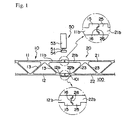
- FIG. 1 is a cross-sectional view of a pair of hollow members according to one embodiment of the present invention;
- FIG. 2 is an enlarged cross-sectional view of a region to be welded of the hollow members in FIG. 1;
- FIG. 3 is a cross-sectional view during welding in FIG. 1;
- FIG. 4 is a cross-sectional view after welding in FIG. 1;
- FIG. 5 is a disassembled cross-sectional view of a rotary tool in FIG. 1;
- FIG. 6 is a perspective view of a car body of a railway car; and
- FIG. 7 is a front view of another embodiment of the present invention.
-
- A preferred embodiment of the present invention will now be explained with reference to FIGS. 1 through 6. In FIG. 4, the shape of the welding region or the friction stir area shown by the cross-hatching is shown as an illustrative example.
- A
car body 500 of a railway car shown in FIG. 6 is comprised of a pair ofside structures 501 constituting the sides, aroof structure 502 constituting the roof, anunderframe 503 constituting the floor, and anend structure 504 constituting the end portion in the longitudinal direction. Theside structure 501, theroof structure 502, and theunderframe 503 are formed by welding plural extrudedmembers extruded members car body 500. Theextruded members - The structure of the
hollow members side structure 501 will now be explained. The same applies to the hollow members used in other structures of the car. - The hollow member 10 (20) is comprised of two substantially parallel face plates 11 (21), 12 (22), and plural connecting plates 13 (23) connecting the two face plates. The connecting plates 13 (23) are inclined from face plates 11 (21), 12(22). That is, the face plates 11 (21), 12 (22) and the connecting plates 13 (23) constitutes a truss.
- The end portion in the width direction of the hollow member 10 (20) protrudes from the junction of the connecting plate 13 (23) and the
face plates 11, 12 (21, 22) so as to form projectingface plates 11b, 12b (21b, 22b). The outer surfaces of theface plates 11b, 12b (21b, 22b) mainly lie in the same plane as or are flush with the outer surfaces of theface plates 11, 12 (21, 22). The thickness of theface plates 11b, 12b (21b, 22b) is more than the thickness offace plates 11, 12 (21, 22). - To the end portions of the
face plates 11b, 12b (21b, 22b), there is provided a convex portion or rib 15 (25) projecting in the outer surface direction (outer side in the thickness direction) of thehollow member recess 16 is formed on the end surfaces of theface plates 11b, 12b. At the end surfaces of theface plates hollow member 20, there is provided a convex portion orrib 26 to be inserted into theconcave portion 16. In order to ease insertion of theconvex portion 26 to theconcave portion 16, theconcave portion 16 and theconvex portion 26 have a trapezoid shape. When inserted, there exists some gap between the bottom surface of theconcave portion 16 and the leading end of theconvex portion 26. - Friction stir welding is performed when the
concave portion 16 and theconvex portion 26 are fitted together. Therefore, this welding could be said to be a welding of a tubular portion comprised offace plates 11, 21 (12, 22) and connectingplates face plate 11 of thehollow member 10 could be called welding of a tube. That is, more generally a case where a supporting member for supporting the insertion force of the rotary tool does not exist at the welding region is called welding of a tube. - Each of the
end surface 17 of theface plates hollow member 10 lie on a line orthogonal to the surface of theface plates 11b, 12b (on a line along the thickness direction of the hollow member). The twoend surfaces 17 lie on the same line. - Each of the
end surfaces 27 of theface plates hollow member 20 exists on a line orthogonal to the surface of theface plates end surfaces 27 lie on the same line. The projections of theconvex portions 26 are equal in size. - The overlap of the
concave portion 16 and theconvex portion 26 of theface plates concave portion 16 and theconvex portion 26 of theface plates 11b, 21b on the upper side. By doing so, theconcave portion 16 and theconvex portion 26 on the upper side are fitted together after theconcave portion 16 and theconvex portion 26 on the lower side are fitted together, so that fitting on the upper side could be performed with ease. - The length of the face plate from the connecting plate at the end portion of the
hollow member 10 to the connectingplate 23 of the other hollow member is longer than the length of the face plate constituting a truss in other areas. Therefore, the thickness of theface plates - The
rotary tool 50 includeslarge diameter portions small diameter portion 51 in the axial direction. The friction stir welding is performed by rotating therotary tool 50 while interposing the region to be welded between the twolarge diameter portions small diameter portion 51 is provided with a male screw thread. At the upper end of therotary tool 50, there is provided a driving device for rotating and moving the tool. Of the twolarge diameter portions large diameter portion 53 is called alarge diameter portion 53 on the base axis side (or on the driving device side). The lowerlarge diameter portion 54 is called alarge diameter portion 54 on the leading end side. - The
rotary tool 50 is comprised of a cylindrical rod 50b including thelarge diameter portion 53 and thesmall diameter portion 51, and amember 54b for thelarge diameter portion 54 on the leading end. The cylindrical rod 50b includes, from the base end side, thelarge diameter portion 53 having a circular outside diameter, a small diameter screw threadedportion 51b, and a small diameter axis portion 51c for installing themember 54b of thelarge diameter portion 54. The axis portion 51c is provided with apin hole 57 for fixing themember 54b. - The
member 54b corresponding to thelarge diameter portion 54 has a circular circumference, and is equipped with ahole 54c fitting with the axis 51c, and a pin hole 58. Each of the end surfaces of thelarge diameter portions screw portion 51b has an inclined annular concavity as is illustrated in FIG. 5. The concavity exists for the function of keeping the stirred metal to the radially inner side, and preventing outflow of the metal to exterior. - After producing the parts as is explained above, the
member 54b corresponding to thelarge diameter portion 54 is fitted to the axis 51c, and themember 54b is fixed by fitting aknock pin 59 to the pin holes 57, 58. Themember 54b becomes thelarge diameter portion 54. - The length L of the small diameter portion 51 (distance from the end surface of the
large diameter portion 53 to the end surface of the large diameter portion 54) is smaller than the thickness t of the member to be welded (including theconvex portions 15, 25). The diameter D of thelarge diameter portion 53 is smaller than the width W of the twoconvex portions - Next, the welding process of the two hollow members will be explained. Two
hollow members bed 100, and theface plates 11b, 12b of themember 10 are abutted against theface plates other member 20. By doing so, theconvex portions 26 of theface plates concave portions 16 of theface plates 11b, 12b. Thehollow members bed 100 in such state. Also, the upperconvex portions - Under this condition, the
rotary tool 50 is rotated and moved from the end surface in the longitudinal direction of thehollow members large diameter portions 53, 54 (with thesmall diameter portion 51 inserted in the members). The region to be welded is welded with the movement of therotary tool 50. - After completing the welding on the side of the
face plates hollow members bed 100 with theface plates face plates - During friction stir welding, the axis of the
rotary tool 50 is slightly inclined, as is known in the art. The axis of the rotary tool is inclined rearward with respect to the direction of movement of therotary tool 50 along the welding line, so that the front end of the upper large diameter portion 53 (front in the direction of movement mentioned above) is positioned upward relative to the rear end (rear in the direction of movement mentioned above). - The rear end of the upper
large diameter portion 53 is positioned inside theconvex portions large diameter portion 53 is positioned above the level outer surfaces of theface plates 11b, 21b adjacent theconvex portions - Consequently, the completed friction stir welded surface on the upper side is positioned upward from the upper surfaces of the
face plates 11b, 21b (12b, 22b). When using the upper surfaces of theface plates convex portions face plates 11b, 21b. Theconvex portions - In the friction stir welding, the gap in the region to be welded (for example, a gap between the
concave portion 16 and theconvex portion 26, a gap between theend surface 17 and the end surface 27) is filled by metal from theconvex portions large diameter portion 53. It is easy for such as gap to be formed, because the length of thecar body 500 may be approximately 20 meters. - The
large diameter portion 54 of the leading end is positioned below theface plates 11b, 21b. The front end of thelarge diameter portion 54 scrapes the lower surface of theface plates 11b, 21b slightly, but the metal is raised slightly at the rear end of thelarge diameter portion 54. The metal is raised downwardly as shown in FIG. 4. - The length of the
car body 500 may be approximately 20 m, so that theface plates hollow members face plates 11b, 21b are fitted together at theconcave portion 16 and theconvex portion 26, so that unevenness caused from the difference of the height position of the end portion of the face plate 11b and the height position of the end portion of theface plate 21b at the region to be welded does not occur. When unevenness occurs, gaps tend to be formed in the interior of the welded region. Therefore, by fitting, a friction stir welding having little defect could be obtained. - During friction stir welding, the two face plates are held between the two
large diameter portions rotary tool 50 towards the side of theface plates face plates 11b, 21b. Therefore, the hollow members could be welded without deformation, even though there exists no supporting plate at the welding region. - In the above embodiment, the
concave portion 16 is formed on each of theface plates 11b, 12b of thehollow member 10, andconvex portion 26 is formed on each of theface plates hollow member 20. However, it is also possible to form theconcave portion 16 on each of theface plates 11b, 22b, and theconvex portion 26 on each of theface plates convex portion 15 on only one member of the abutted region. - The embodiment illustrated in FIG. 7 is a case where end portions butted together by bending a plate circularly are friction stir welded to obtain a cylinder. The
same rotary tool 50 is used. When welding with a conventional rotary tool, welding is performed while a supporting member is placed inside the cylinder. Or, welding is performed by positioning the welding region downward, and placing the rotary tool inside the cylinder. In such cases, welding of a small diameter cylinder is difficult, since the placement of a supporting member or a rotary tool is difficult. However, by performing welding by locating the region to be welded between the two large diameter portions, a small diameter cylinder could be welded with simple structure. - The friction stir welding method here described can be applied not only to cylinders, but it could also be applied to tubes bent in square shape and the like. Moreover, it could be applied to cases for welding in the circumferential direction. For example, it could be applied to the case of butting a first tubular member against a second tubular member in the axial direction, and welding the same in the circumferential direction. These tubular members are for example cylinders. In this case, a hole for inserting the
large diameter portion 54 of the leading end of the rotary tool is formed at the starting point of the welding, and welding is completed at the position of the hole. After completing the welding, the hole is filled, e.g. by arc welding, or by arc welding a filling plate. - The technical scope of the present invention is not limited to the terms used in the claims or in the summary of the present invention, but is extended for example to the range in which a person skilled in the art could easily substitute based on the present disclosure.
- The present invention thus permits friction stir welding without deforming a tubular structure such as hollow members and the like.
Claims (13)
- A friction stir welding method, comprising:butting opposed end portions of plates of a hollow structure assembly; andusing a rotary tool having large diameter portions on both ends of a small diameter portion, rotating and moving said rotary tool along the butted region with the butted region interposed between the two large diameter portions of the rotary tool.
- A friction stir welding method according to claim 1, wherein:
said end portions at the butted region have respectively opposed concave and convex portions, and are abutted against each other with said convex portion on one member inserted in said concave portion on the other member. - A friction stir welding method according to claim 1 or 2, wherein:an external surface of the end portion of at least one said face plate is provided with an outward convex portion; andthe friction stir welding is performed with inserting the large diameter portion on the outer side of said rotary tool inserted into said outward convex portion.
- A friction stir welding method, comprising:butting two face plates of a first hollow member against two face plates of a second hollow member; andusing a rotary tool having large diameter portions on both ends of a small diameter portion, rotating and moving said rotary tool along the butted region with the butted region interposed between the two large diameter portions of said rotary tool.
- A friction stir welding method according to claim 4, wherein:
the members at each of said butted regions include respectively opposed concave and convex portions, and are abutted against each other with the convex portion on one member inserted in said concave portion on the other member. - A friction stir welding method according to claim 4 or 5, wherein:each of external surfaces of the end portions of said two face plates of said first hollow member and each of external surfaces of the end portions of said two face plates of said second hollow member are provided with an outward convex portion; andsaid friction stir welding is performed while inserting the large diameter portion on the outer side of said rotary tool inside said outward convex portions.
- A friction stir welding method, comprising:bending a plate to form a tubular shape, and butting one end portion of said plate against the other end portion; andusing a rotary tool having large diameter portions on both ends of a small diameter portion, rotating and moving said rotary tool along the butted region while said butted region is interposed between said two large diameter portions of said rotary tool.
- A friction stir welding method, comprising:butting a first tubular member against a second tubular member; andusing a rotary tool having large diameter portions on both ends of a small diameter portion, rotating and moving said rotary tool along the butted region while said butted region is interposed between said two large diameter portions of said rotary tool.
- A structural body, wherein:a butted region of end portions of plates at one side of a hollow structure are joined by a friction stir weld;the friction stir welded region exists on both sides in the direction of thickness of the welded region; andsaid friction stir welded region at its side facing the other side of the hollow structure is raised from the surfaces of said plates.
- A tube, wherein:a friction stir weld is present in the axial direction of the tube;the friction stir welded region exists on both sides in the direction of thickness of the welded region; andthe friction stir welded region at the side facing the inner side of said tube is raised from the surface of the plate constituting said tube.
- A tube, wherein:a butted region between a first tube portion and a second tube portion is joined by a friction stir weld;the friction stir welded region exists on both sides in the direction of thickness of the welded region; andthe friction stir welded region at the side facing the inner side of said tube is raised from the surface of plates constituting said tube portion.
- A hollow member for friction stir welding, wherein:said hollow member comprises a first face plate, a second face plate substantially parallel to said first face plate, and a plural connecting plates connecting said first face plate and said second face plate;an end portion of said first face plate and an end portion of said second face plate is protruded in the width direction of said hollow member compared to the connecting region of said connecting plate with said first face plate and said second face plate;an end surface of said protruded end portion of said first face plate includes a concave portion or a convex portion; andan end surface of said protruded end portion of said second face plate on the side facing said concave portion or said convex portion includes a concave portion or a convex portion.
- A hollow member for friction stir welding according to claim 12, wherein each of said first face plate and said second face plate has adjacent said end surface thereof at the outer surface thereof an outward convex portion.
Applications Claiming Priority (2)
| Application Number | Priority Date | Filing Date | Title |
|---|---|---|---|
| JP2000259053A JP2002066764A (en) | 2000-08-29 | 2000-08-29 | Friction stir welding method |
| JP2000259053 | 2000-08-29 |
Publications (1)
| Publication Number | Publication Date |
|---|---|
| EP1193022A2 true EP1193022A2 (en) | 2002-04-03 |
Family
ID=18747275
Family Applications (1)
| Application Number | Title | Priority Date | Filing Date |
|---|---|---|---|
| EP01301560A Withdrawn EP1193022A2 (en) | 2000-08-29 | 2001-02-21 | Friction stir welding |
Country Status (7)
| Country | Link |
|---|---|
| US (1) | US20020023941A1 (en) |
| EP (1) | EP1193022A2 (en) |
| JP (1) | JP2002066764A (en) |
| KR (1) | KR20020017899A (en) |
| CN (1) | CN1340399A (en) |
| AU (1) | AU2310301A (en) |
| TW (1) | TW492900B (en) |
Families Citing this family (7)
| Publication number | Priority date | Publication date | Assignee | Title |
|---|---|---|---|---|
| JP3751215B2 (en) * | 2001-04-16 | 2006-03-01 | 株式会社日立製作所 | Friction stir welding method |
| JP2003039181A (en) * | 2001-07-24 | 2003-02-12 | Hitachi Ltd | Friction stir welding method and rotary tool |
| US7370452B2 (en) * | 2002-09-16 | 2008-05-13 | Rogers Melissa B | Mat assembly for heavy equipment transit and support |
| JP5352226B2 (en) * | 2008-12-25 | 2013-11-27 | 日本車輌製造株式会社 | Laser welded joint with double skin panel |
| CN103934565B (en) * | 2011-01-19 | 2016-09-14 | 日本轻金属株式会社 | The friction stirring connecting method of double face slab |
| CN109317814A (en) * | 2018-10-26 | 2019-02-12 | 平高集团有限公司 | A friction stir welding method for a barrel weld |
| IT202000031940A1 (en) * | 2020-12-22 | 2022-06-22 | Miwenti S R L | METHOD OF MAKING AN INGOT MOLD AND WELDING MACHINE FOR INGOT MOLD |
-
2000
- 2000-08-29 JP JP2000259053A patent/JP2002066764A/en active Pending
-
2001
- 2001-02-13 TW TW090103152A patent/TW492900B/en active
- 2001-02-14 KR KR1020010007223A patent/KR20020017899A/en not_active Withdrawn
- 2001-02-15 CN CN01104541A patent/CN1340399A/en active Pending
- 2001-02-20 AU AU23103/01A patent/AU2310301A/en not_active Abandoned
- 2001-02-21 EP EP01301560A patent/EP1193022A2/en not_active Withdrawn
- 2001-02-26 US US09/791,552 patent/US20020023941A1/en not_active Abandoned
Also Published As
| Publication number | Publication date |
|---|---|
| TW492900B (en) | 2002-07-01 |
| KR20020017899A (en) | 2002-03-07 |
| US20020023941A1 (en) | 2002-02-28 |
| CN1340399A (en) | 2002-03-20 |
| JP2002066764A (en) | 2002-03-05 |
| AU2310301A (en) | 2002-03-07 |
Similar Documents
| Publication | Publication Date | Title |
|---|---|---|
| US6532712B2 (en) | Structural body and method of manufacture thereof | |
| US6354483B1 (en) | Friction stir welding method | |
| KR100526713B1 (en) | Friction stir welding method and hollow member therefor | |
| US6599641B1 (en) | Structural body formed by friction stir welding of hollow extruded frame members | |
| AU5362800A (en) | Friction stir joining method | |
| US6557746B2 (en) | Friction stir bonding method | |
| US20030042293A1 (en) | Friction stir welding method and panel structure for friction stir welding | |
| EP1193022A2 (en) | Friction stir welding | |
| JP4737768B2 (en) | Detachable tow hook mounting structure | |
| EP0846931A2 (en) | Oil cooler mounting structure and oil cooler mounting method | |
| JP3556888B2 (en) | Hollow sections for friction stir welding | |
| JPH07227670A (en) | Plug welding method for metal plate member | |
| JP2002160076A (en) | How to make a structure | |
| JP4372625B2 (en) | Friction stir welding method for metal member and metal joint | |
| EP1201348A2 (en) | Friction stir welding method | |
| JPH11216594A (en) | Column backing metal for steel frame construction | |
| JP2020066033A (en) | Dissimilar material joining method, dissimilar material joining joint, tubular member with auxiliary member for joining dissimilar materials, and manufacturing method thereof | |
| KR20000017352U (en) | Pipe connectors | |
| JP2002096164A (en) | Insert fittings for pipe welding | |
| JPH09202163A (en) | Seat slide device | |
| JP2002316274A (en) | Hollow profile for friction stir welding | |
| JP2001003515A (en) | Steel pipe column | |
| JPH06136825A (en) | Steel pipe pillar connection hardware |
Legal Events
| Date | Code | Title | Description |
|---|---|---|---|
| PUAI | Public reference made under article 153(3) epc to a published international application that has entered the european phase |
Free format text: ORIGINAL CODE: 0009012 |
|
| AK | Designated contracting states |
Kind code of ref document: A2 Designated state(s): AT BE CH CY DE DK ES FI FR GB GR IE IT LI LU MC NL PT SE TR |
|
| AX | Request for extension of the european patent |
Free format text: AL;LT;LV;MK;RO;SI |
|
| STAA | Information on the status of an ep patent application or granted ep patent |
Free format text: STATUS: THE APPLICATION HAS BEEN WITHDRAWN |
|
| 18W | Application withdrawn |
Withdrawal date: 20021022 |