EP1192098B1 - Partitioned composting cage - Google Patents
Partitioned composting cage Download PDFInfo
- Publication number
- EP1192098B1 EP1192098B1 EP00935311A EP00935311A EP1192098B1 EP 1192098 B1 EP1192098 B1 EP 1192098B1 EP 00935311 A EP00935311 A EP 00935311A EP 00935311 A EP00935311 A EP 00935311A EP 1192098 B1 EP1192098 B1 EP 1192098B1
- Authority
- EP
- European Patent Office
- Prior art keywords
- auger
- cage
- trough
- composted
- composting
- Prior art date
- Legal status (The legal status is an assumption and is not a legal conclusion. Google has not performed a legal analysis and makes no representation as to the accuracy of the status listed.)
- Expired - Lifetime
Links
Images



Classifications
-
- C—CHEMISTRY; METALLURGY
- C05—FERTILISERS; MANUFACTURE THEREOF
- C05F—ORGANIC FERTILISERS NOT COVERED BY SUBCLASSES C05B, C05C, e.g. FERTILISERS FROM WASTE OR REFUSE
- C05F17/00—Preparation of fertilisers characterised by biological or biochemical treatment steps, e.g. composting or fermentation
- C05F17/90—Apparatus therefor
- C05F17/95—Devices in which the material is conveyed essentially vertically between inlet and discharge means
- C05F17/955—Devices in which the material is conveyed essentially vertically between inlet and discharge means the material going from platform to platform
-
- C—CHEMISTRY; METALLURGY
- C05—FERTILISERS; MANUFACTURE THEREOF
- C05F—ORGANIC FERTILISERS NOT COVERED BY SUBCLASSES C05B, C05C, e.g. FERTILISERS FROM WASTE OR REFUSE
- C05F17/00—Preparation of fertilisers characterised by biological or biochemical treatment steps, e.g. composting or fermentation
- C05F17/90—Apparatus therefor
- C05F17/964—Constructional parts, e.g. floors, covers or doors
-
- C—CHEMISTRY; METALLURGY
- C05—FERTILISERS; MANUFACTURE THEREOF
- C05F—ORGANIC FERTILISERS NOT COVERED BY SUBCLASSES C05B, C05C, e.g. FERTILISERS FROM WASTE OR REFUSE
- C05F17/00—Preparation of fertilisers characterised by biological or biochemical treatment steps, e.g. composting or fermentation
- C05F17/90—Apparatus therefor
- C05F17/964—Constructional parts, e.g. floors, covers or doors
- C05F17/971—Constructional parts, e.g. floors, covers or doors for feeding or discharging materials to be treated; for feeding or discharging other material
-
- Y—GENERAL TAGGING OF NEW TECHNOLOGICAL DEVELOPMENTS; GENERAL TAGGING OF CROSS-SECTIONAL TECHNOLOGIES SPANNING OVER SEVERAL SECTIONS OF THE IPC; TECHNICAL SUBJECTS COVERED BY FORMER USPC CROSS-REFERENCE ART COLLECTIONS [XRACs] AND DIGESTS
- Y02—TECHNOLOGIES OR APPLICATIONS FOR MITIGATION OR ADAPTATION AGAINST CLIMATE CHANGE
- Y02P—CLIMATE CHANGE MITIGATION TECHNOLOGIES IN THE PRODUCTION OR PROCESSING OF GOODS
- Y02P20/00—Technologies relating to chemical industry
- Y02P20/141—Feedstock
- Y02P20/145—Feedstock the feedstock being materials of biological origin
-
- Y—GENERAL TAGGING OF NEW TECHNOLOGICAL DEVELOPMENTS; GENERAL TAGGING OF CROSS-SECTIONAL TECHNOLOGIES SPANNING OVER SEVERAL SECTIONS OF THE IPC; TECHNICAL SUBJECTS COVERED BY FORMER USPC CROSS-REFERENCE ART COLLECTIONS [XRACs] AND DIGESTS
- Y02—TECHNOLOGIES OR APPLICATIONS FOR MITIGATION OR ADAPTATION AGAINST CLIMATE CHANGE
- Y02W—CLIMATE CHANGE MITIGATION TECHNOLOGIES RELATED TO WASTEWATER TREATMENT OR WASTE MANAGEMENT
- Y02W30/00—Technologies for solid waste management
- Y02W30/40—Bio-organic fraction processing; Production of fertilisers from the organic fraction of waste or refuse
Definitions
- This invention concerns a composing cage according to the preamble of claim 1. It is particularly, but not exclusively suitable for composing biological waste material on an industrial scale, where at least tens of kilograms of such waste are to be loaded per day.
- An even distribution of material within the cage is also very important so that there are no higher (deeper) areas of material where it may tend to compact and also so that an evenly degraded layer of material of relatively constant thickness can be regularly removed from the base of the cage.
- Loading of the cage has hitherto been carried out by an elongate trough, extending the full width of the cage, and permanently mounted above the cage so as to slide therealong.
- the trough is loaded with a suitable mixture of material to be composted from a sloping elevator assembly at one end of the cage, and then slides along the top of the cage to dispense the material to one or more selected compartments.
- the material ideally needs to be scattered or sprinkled so that it is aerated, but it must also be spread as evenly as possible.
- a further problem is associated with removal of composted material from the base of the compartment. As described in FR-A-2 473 038, this is accomplished by an auger mounted below the mesh enclosure between respective guide rails and capable of travelling therealong either continuous or intermittently whilst also rotating. Hitherto, the auger has been mounted onto the rails by way of respective motorised trolleys at each end. In order to remove composted material evenly, it is important to try and move the respective ends of the auger at the same rate, so that the axis of the auger remains substantially perpendicular to the direction of travel. This has proved difficult.
- the auger is now moved intermittently along the respective guide rails by a co-ordinated system of hydraulic rams comprising a pair of piston assemblies at each end of the auger which are operable in synchrony to hold the auger perpendicular to the direction of travel.
- these piston assemblies have a common hydraulic power supply, which links to those at one end of the auger through an axial passage of the auger.
- the rams will generally move the ends of the auger to the same extent and will not allow them to become significantly out of alignment with each other.
- the trough has a base provided by a plurality of side by side rotors having circumferential vanes and radially extending cross-walls whereby the material to be composted can be distributed to the compartments.
- the trough preferably has a plurality of flaps mounted below the rotors, these flaps being operable by a lever mechanism upon actuation of the rotors.
- a hydraulic lift is provided for raising and lowering the trough between a low level filling station and the top of the cage.
- the trough can be evenly loaded with much greater accuracy, by visual inspection, by means of a conventional mechanical shovel or similar loading equipment.
- the illustrated embodiment of composting cage has all three aspects of the invention applied to thereto.
- the cage comprises a large, rectangular or mesh enclosure supported by a framework of upright beams (10, 11, 12, etc) interconnecting substantially horizontal crosspieces (13), and interconnecting oblique struts as well as oblique supporting stanchions (14).
- the cage is divided transversely into a plurality of compartments of equal width by respective mesh partitions. In a standard cage there may be eight such compartments. Others may be added in two compartment modules.
- the cage may be about 12 feet (3.6m) in height, but is supported by some of the vertical beams (10) of the framework about 2ft (0.6m) above ground level. Thus a gap remains between the bottom of the enclosures defined by the partitioned cage and the ground to permit removal of the composted material.
- Material to be composted is mixed in appropriate proportions - coarse, fine, green, nitrogen-rich, partially rotted, etc - and then fed at intervals, e.g. daily, into the top of the respective compartments of the cage. Composted materials is also removed periodically, probably also daily, from the base of the cage so that there is a continuous process in operation.
- a trough (20) is provided as part of the composting cage apparatus to feed material into the top of the compartments. It comprises a front wall (22), a rear wall (24) and respective side walls (26) ( Figures 1 and 2).
- the rear wall (24) is higher than the front wall (22).
- the base of the trough (20) is provided by a plurality of substantially parallel rotors (not shown) which extend transversely of the cage. These rotors carry circumferential vanes and radially extending cross walls, so that when they rotate, loose material in the trough (20) will be carried round in the resulting recesses or pockets and will fall from the base of the trough (20).
- a plurality of flaps are disposed below the rotors. These flaps are pivotally mounted in the manner of louvres. They are generally arranged in close side-by-side adjacency, in a closed condition.
- a partition (28) in the centre of the trough (20) houses a mechanism for opening the flaps.
- Each of the flaps carries a downwardly extending lever, and each lever is connected pivotally to a linkage mechanism (29) which pivots at a higher level adjacent the partition (28).
- a rotary cam (not shown) acts on a ratchet which is pivotally connected near the top of the linkage (29).
- the ratchet is released, causing the linkage (29) to pivot, which then moves the levers and this causes the flaps to open to a substantially vertical position under their own weight.
- the trough (20) is mounted on four wheels (21), one at the front and rear of the bottom of each side wall (26). Also attached externally to the side walls (26) are motors (35) and chain drives for actuation of the rotors in the base of the trough. Motors (27) for driving the aforesaid wheels (21) are mounted on the rear wall (24).
- the trough (20) is shown at its loading station at the front of the mesh enclosures of the cage. It is arranged close to the ground on a platform (30) which is part of a hydraulic lift mechanism.
- a pair of lift cables (32) are shown, which are extensible by the action of a hydraulic ram (not shown) at the right hand side.
- the cables (32) extend adjacent the inside of respective H-profile beams (11), which are substantially in line with the mid-point between the front and rear walls (22, 24) of the trough (20).
- the cables (32) are attached to respective elevator plates (34) which are mounted between the upright beams (10, 12) also of H-section, by way of wheels (36).
- These wheels (36) are guided between the beams (10, 12) as plates (34) are raised and lowered by the hydraulic cables (32).
- the plates (34) are connected to the platform (30) at each end so that the platform (30) and the trough (20) mounted on it are raised and lowered therewith.
- the trough (20) is filled at ground level by a mechanical shovel, or similar device, and it can be filled evenly and to an adequate level by inspections by the loading operator.
- the hydraulic lift (30-36) is then actuated and the trough (20) is raised to the top of the front of the cage.
- a limit switch is actuated by the trough (20) to start up the motors (27) which drives its wheels (21) (power for the motor being supplied via a cable reel). It then moves off the platform (30) and travels along rails provided at the top of the cage sides until it reaches the cage compartment for which its load is destined. This is preprogrammed by the operator from a central control unit.
- the motors (25) for the rotors are actuated simultaneously with the rotary cam which releases the flaps.
- the load is then dispensed evenly into the compartment, and the trough (20) then travels backwards towards the platform (30) at the front of the cage.
- a part of the linkage (29) in the flap release mechanism makes contact with an upward, stationary projection located substantially centrally of one of the cage partitions and this causes the flaps to close again. To ensure that this happens there is a similar projection at the top of each cage partition, so if one of them fails to return the flaps for some reason, the next adjacent one will do it.
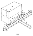
- an auger (40) is mounted below the base of the mesh enclosure. It extends between respective guide rails (42) provided by I-beams which are mounted below and outwardly of the longitudinal side walls of the cage.
- the axis of the auger (40) is tubular, as is apparent from Figure 4. It has a helical flight (44) which increases in diameter and also in pitch along its length, i.e. across the transverse extent of the cage. This is necessary to try and ensure an even removal of composted material across the width of the cage, the material being transported towards the end of the auger (40) with the larger diameter flight (44).
- a cross piece, or other conformation is preferably provided to facilitate break up of the compost to enable its removal.
- it is fairly well compacted at the base of the cage where it may have been resident and undergoing aerobic degradation for up to 21 days.
- Each end of the auger (40) is mounted, for rotation, in a respective bearing block (46), which is connected to a slide plate (48), which rests upon the respective rail (42.
- a power pack (50) for operation of the auger (40) is connected to the slide plate (48).
- a motor (51) and drive belt (52) for rotation of the auger are connected to the power pack (50).
- Respective piston and cylinder assemblies (54, 55) extend in opposite directions from each bearing (46), the piston, in each case, carrying at its free end a gripper (56, 57) which is engagable with the respective rail (42).
- Each gripper (56, 57) has a pair of lugs or teeth or hooks (not shown) in its undersurface which selectively engage in corresponding pairs of apertures (not shown) which are formed at spaced intervals along each rail (42).
- the piston and cylinder assemblies (54, 55) at the opposing ends of the auger have a common hydraulic supply from the power pack (50).
- pipes (58) for supply of hydraulic fluid to the assemblies (54, 55) remote from the power pack (50) extend through an axial space (60) in the auger (40) itself.
- the pairs of piston assemblies (54, 55) at each end of the auger (40) operate substantially in synchrony with each other so as to move the auger (40) along the rails (42) below the composting enclosure with the auger held substantially perpendicular to the direction of travel.
- the auger (40) is moved intermittently by sequential operation of the forward and rearward assembly (54, 55).
- the auger (40) is considered to be at or near the front of the cage and moving towards the rear, then starting with the gripper (56) of each forward piston firmly locked to the rail (42) and the piston of each forward assembly (54) fully retracted, the gripper (57) of each rear piston will automatically be slightly tilted relative to the rail (42) so that its teeth (or lugs or hooks) disengage.
- the piston of each forward assembly (54) is then extended, thus moving the bearings (46) and the auger (40) towards the rear.
- the auger (40) moves quite slowly, maybe only about 1 ⁇ 2m in a period of 21 ⁇ 2 minutes.
- the pistons (rams) act with a constant force, e.g of 8 tonnes. Once the pistons of each rearward assembly (55) are fully extended the grippers (57) attached to them will disengage from the rail (42) by retraction of the piston. The grippers (57) will then re-engage further rearward pairs of apertures in the respective rails (42) by re-extensions of the piston (55).
- the auger (40) will always move down the full length of the cage, removing the bottom 1ft (30cm) or thereabouts of compost, which is disgorged onto a conveyor along one side of the cage.
- the auger (40) needs to move the entire length so as to ensure substantially even removal and so as to maintain the momentum of breaking up the compacted lowest layer of composted material.
Landscapes
- Chemical & Material Sciences (AREA)
- Chemical Kinetics & Catalysis (AREA)
- Life Sciences & Earth Sciences (AREA)
- Engineering & Computer Science (AREA)
- Biochemistry (AREA)
- Biotechnology (AREA)
- Health & Medical Sciences (AREA)
- General Chemical & Material Sciences (AREA)
- Microbiology (AREA)
- Molecular Biology (AREA)
- Organic Chemistry (AREA)
- Fertilizers (AREA)
- Processing Of Solid Wastes (AREA)
Abstract
Description
Claims (7)
- A composting cage comprising a mesh enclosure divided into a plurality of compartments and an auger (40) mounted below the mesh enclosure between respective guide rails (42) and capable of travelling therealong by intermittent movement to extract compost from the base of each compartment characterised in that the auger (40) is movable along the respective guide rails (42) by a co-ordinated system of hydraulic rams (54, 55) comprising a pair of piston assemblies at each end of the auger (40) which are operable in synchrony to hold the auger perpendicular to the direction of travel.
- A composting cage according to claim 1 wherein the piston assemblies (54, 55) have a common hydraulic power supply, which links to those at one end of the auger through the axis of the auger (40).
- A composting cage according to claim 1 or 2 wherein the piston assemblies (54, 55) connect to the respective guide rails (42) by gripper means (56, 57) which selectively engage the rails (42) at predetermined intervals.
- A composting cage according to claim 1, 2 or 3 and further comprising a trough (20) for reception of material to be composted, which trough (20) is capable of travelling across the top of the cage to dispense the material to be composted into the compartments and has a base provided by a plurality of side by side rotors, each having circumferential vanes and radially extending cross walls, whereby the material to be composted can be distributed to the compartments.
- A composting cage according to claim 4 wherein the trough (20) has a plurality of flaps mounted below the rotors, these flaps being openable by a lever mechanism upon actuation of the rotors.
- A composting cage according to claim 4 or 5 wherein the flaps are closable by contact with projections from the top of the cage as the trough travels in reverse direction after dispensing its load of material to be composted.
- A composting cage according to claim 4, 5 or 6 wherein a hydraulic lift (30-36) is provided for raising and lowering the trough (20) between a low level filling station and the top of the cage and wherein the trough is provided with wheels and a motor, whereby the trough is able to travel along tracks provided along the top of the cage.
Applications Claiming Priority (3)
| Application Number | Priority Date | Filing Date | Title |
|---|---|---|---|
| GB9912525A GB2350355B (en) | 1999-05-28 | 1999-05-28 | Partitioned composting cage |
| GB9912525 | 1999-05-28 | ||
| PCT/GB2000/001975 WO2000073181A1 (en) | 1999-05-28 | 2000-05-23 | Partitioned composting cage |
Publications (2)
| Publication Number | Publication Date |
|---|---|
| EP1192098A1 EP1192098A1 (en) | 2002-04-03 |
| EP1192098B1 true EP1192098B1 (en) | 2004-03-03 |
Family
ID=10854400
Family Applications (1)
| Application Number | Title | Priority Date | Filing Date |
|---|---|---|---|
| EP00935311A Expired - Lifetime EP1192098B1 (en) | 1999-05-28 | 2000-05-23 | Partitioned composting cage |
Country Status (11)
| Country | Link |
|---|---|
| US (1) | US6489161B2 (en) |
| EP (1) | EP1192098B1 (en) |
| AT (1) | ATE260855T1 (en) |
| AU (1) | AU5086500A (en) |
| CA (1) | CA2375010C (en) |
| CZ (1) | CZ20014276A3 (en) |
| DE (1) | DE60008739T2 (en) |
| ES (1) | ES2216898T3 (en) |
| GB (1) | GB2350355B (en) |
| WO (1) | WO2000073181A1 (en) |
| ZA (1) | ZA200109214B (en) |
Families Citing this family (2)
| Publication number | Priority date | Publication date | Assignee | Title |
|---|---|---|---|---|
| FR2839305B1 (en) * | 2002-05-03 | 2005-02-18 | Audit Conseil Efficacite Strat | MODULAR AND OPTIMIZED INSTALLATION FOR COMPOSTING ORGANIC MATERIALS |
| GB2442723B (en) * | 2006-08-31 | 2011-04-06 | Teg Environmental Plc | Partitioned composting cage |
Family Cites Families (15)
| Publication number | Priority date | Publication date | Assignee | Title |
|---|---|---|---|---|
| GB900384A (en) * | 1959-07-14 | 1962-07-04 | John Thompson Ind Const Ltd | Improvements in or relating to apparatus for the continuous treatment of finely divided materials |
| DE2329366A1 (en) * | 1973-06-08 | 1975-01-02 | Schnorr Karl Ernst | Second stage fermentor - for crude compost from fermentation of household waste |
| DE2331622C3 (en) * | 1973-06-22 | 1986-06-19 | Karl-Ernst 6601 Klarenthal Schnorr | Continuously working rotting silo |
| FR2348871A1 (en) * | 1976-04-23 | 1977-11-18 | Breschard Jean Marc | Bulk material unloading and storage equipment - has receiving skip below ground level transported to above selected receiving cell |
| GB2001548B (en) * | 1977-05-19 | 1982-01-27 | Brunt L | Means for releasably supporting a bed or layer of loose material |
| JPS5454877A (en) * | 1977-10-08 | 1979-05-01 | Ebara Mfg | Compost making apparatus |
| FR2473038A1 (en) * | 1980-01-08 | 1981-07-10 | Traitement Indl Gadoues | Plant to mfr. compost by fermenting organic waste - uses modular parallelepiped, fermenting vessels served by common mobile discharge conveyor |
| US4397674A (en) * | 1981-11-20 | 1983-08-09 | Bancohio National Bank | Material treatment and windrowing apparatus |
| EP0196887A3 (en) * | 1985-03-29 | 1987-05-27 | National Research Development Corporation | Vermicomposting system |
| SE448723B (en) * | 1985-04-29 | 1987-03-16 | Purac Ab | DEVICE FOR CHARGING OF CORN OR MASSIVE MATERIAL ON CONSTANT LEVEL AND WITH A SINGLE SURFACE AND USE OF THIS DEVICE FOR SUPPLYING MATERIAL TO A COMPOSITIONING CONTAINER |
| FR2653687B1 (en) * | 1989-10-27 | 1992-05-07 | Sovadec Valorisation Dechets | LOMBRICOMPOST TREATMENT PROCESS AND DEVICE FOR IMPLEMENTING SAME. |
| ATE104656T1 (en) * | 1991-07-11 | 1994-05-15 | Jost Heimberg Maschf | COMPOSTING PLANT. |
| DE59306649D1 (en) * | 1992-10-05 | 1997-07-10 | Rindelaub Frank Alex Erich | Composting plant |
| KR0184018B1 (en) * | 1994-02-03 | 1999-04-01 | 김백기 | Excrement aerobic fermentation apparatus and manure using it |
| DE19807035A1 (en) * | 1997-11-12 | 1999-05-27 | Herhof Umwelttechnik Gmbh | Installation for composting waste, consisting of composting containers arranged one above the other and provided with means for filling and emptying them |
-
1999
- 1999-05-28 GB GB9912525A patent/GB2350355B/en not_active Expired - Fee Related
-
2000
- 2000-05-23 EP EP00935311A patent/EP1192098B1/en not_active Expired - Lifetime
- 2000-05-23 AT AT00935311T patent/ATE260855T1/en not_active IP Right Cessation
- 2000-05-23 WO PCT/GB2000/001975 patent/WO2000073181A1/en not_active Ceased
- 2000-05-23 CA CA 2375010 patent/CA2375010C/en not_active Expired - Fee Related
- 2000-05-23 CZ CZ20014276A patent/CZ20014276A3/en unknown
- 2000-05-23 AU AU50865/00A patent/AU5086500A/en not_active Abandoned
- 2000-05-23 DE DE2000608739 patent/DE60008739T2/en not_active Expired - Fee Related
- 2000-05-23 ES ES00935311T patent/ES2216898T3/en not_active Expired - Lifetime
-
2001
- 2001-11-08 ZA ZA200109214A patent/ZA200109214B/en unknown
- 2001-11-26 US US09/991,886 patent/US6489161B2/en not_active Expired - Lifetime
Also Published As
| Publication number | Publication date |
|---|---|
| DE60008739D1 (en) | 2004-04-08 |
| WO2000073181A1 (en) | 2000-12-07 |
| CA2375010C (en) | 2008-08-26 |
| DE60008739T2 (en) | 2005-02-10 |
| AU5086500A (en) | 2000-12-18 |
| CA2375010A1 (en) | 2000-12-07 |
| GB9912525D0 (en) | 1999-07-28 |
| GB2350355A (en) | 2000-11-29 |
| US6489161B2 (en) | 2002-12-03 |
| ES2216898T3 (en) | 2004-11-01 |
| US20020064868A1 (en) | 2002-05-30 |
| ATE260855T1 (en) | 2004-03-15 |
| GB2350355B (en) | 2003-04-23 |
| CZ20014276A3 (en) | 2002-03-13 |
| EP1192098A1 (en) | 2002-04-03 |
| ZA200109214B (en) | 2002-06-26 |
Similar Documents
| Publication | Publication Date | Title |
|---|---|---|
| DE69500955T2 (en) | Method and device for processing animals | |
| US4414335A (en) | Composting system with movable process cars | |
| US3962965A (en) | Plant for the compression of garbage | |
| EP3945044B1 (en) | Floor-bound steady conveyor | |
| KR20210145813A (en) | Apparatus for working and homogenizing loose or non-cohesive masses of material and method of operation of such apparatus | |
| CA2375010C (en) | Partitioned composting cage | |
| EP0064257B1 (en) | Putrefaction plant | |
| KR20010034743A (en) | Treatment of waste materials | |
| EP1769895A1 (en) | Processing line for producing multilayer building blocks provided with a decorative face | |
| KR200294434Y1 (en) | Earthworm breeding device for casting production | |
| US9040289B2 (en) | Gravity assisted compost reactor | |
| US4199912A (en) | Method and apparatus for filling containers with a relatively viscous material | |
| EP0679149B1 (en) | Installation for the temporary storage of bulk goods | |
| CN115250834B (en) | Device for batch transportation and field arrangement of edible fungus sticks | |
| CN115152651A (en) | Transport vehicle for cultivation | |
| CN215038672U (en) | Circulating hopper mechanism and concrete prefabricated part production device with same | |
| CN223495532U (en) | Sand and stone bidirectional distributing device | |
| JP2000063190A (en) | Fermentation composting equipment | |
| CN115307952B (en) | Household garbage sampling system and method | |
| RU2034459C1 (en) | Device for breeding earthworms | |
| CN2451246Y (en) | Automatic garbage fermentation bin | |
| JP3663384B2 (en) | Fermentation decomposition equipment | |
| KR20040006777A (en) | Earthworm breeding device for casting production | |
| DE29623667U1 (en) | Component that can be used for stationary or transportable use for the bio-recycling of substances | |
| EP0253481A2 (en) | Improved composting plant |
Legal Events
| Date | Code | Title | Description |
|---|---|---|---|
| PUAI | Public reference made under article 153(3) epc to a published international application that has entered the european phase |
Free format text: ORIGINAL CODE: 0009012 |
|
| 17P | Request for examination filed |
Effective date: 20011213 |
|
| AK | Designated contracting states |
Kind code of ref document: A1 Designated state(s): AT BE CH CY DE DK ES FI FR GB GR IE IT LI LU MC NL PT SE |
|
| AX | Request for extension of the european patent |
Free format text: AL;LT;LV;MK;RO;SI |
|
| 17Q | First examination report despatched |
Effective date: 20020531 |
|
| GRAP | Despatch of communication of intention to grant a patent |
Free format text: ORIGINAL CODE: EPIDOSNIGR1 |
|
| GRAS | Grant fee paid |
Free format text: ORIGINAL CODE: EPIDOSNIGR3 |
|
| GRAA | (expected) grant |
Free format text: ORIGINAL CODE: 0009210 |
|
| AK | Designated contracting states |
Kind code of ref document: B1 Designated state(s): AT BE CH CY DE DK ES FI FR GB GR IE IT LI LU MC NL PT SE |
|
| PG25 | Lapsed in a contracting state [announced via postgrant information from national office to epo] |
Ref country code: FI Free format text: LAPSE BECAUSE OF FAILURE TO SUBMIT A TRANSLATION OF THE DESCRIPTION OR TO PAY THE FEE WITHIN THE PRESCRIBED TIME-LIMIT Effective date: 20040303 Ref country code: LI Free format text: LAPSE BECAUSE OF FAILURE TO SUBMIT A TRANSLATION OF THE DESCRIPTION OR TO PAY THE FEE WITHIN THE PRESCRIBED TIME-LIMIT Effective date: 20040303 Ref country code: NL Free format text: LAPSE BECAUSE OF FAILURE TO SUBMIT A TRANSLATION OF THE DESCRIPTION OR TO PAY THE FEE WITHIN THE PRESCRIBED TIME-LIMIT Effective date: 20040303 Ref country code: CH Free format text: LAPSE BECAUSE OF FAILURE TO SUBMIT A TRANSLATION OF THE DESCRIPTION OR TO PAY THE FEE WITHIN THE PRESCRIBED TIME-LIMIT Effective date: 20040303 Ref country code: CY Free format text: LAPSE BECAUSE OF FAILURE TO SUBMIT A TRANSLATION OF THE DESCRIPTION OR TO PAY THE FEE WITHIN THE PRESCRIBED TIME-LIMIT Effective date: 20040303 |
|
| REG | Reference to a national code |
Ref country code: GB Ref legal event code: FG4D |
|
| REG | Reference to a national code |
Ref country code: CH Ref legal event code: EP |
|
| REG | Reference to a national code |
Ref country code: IE Ref legal event code: FG4D |
|
| REF | Corresponds to: |
Ref document number: 60008739 Country of ref document: DE Date of ref document: 20040408 Kind code of ref document: P |
|
| PG25 | Lapsed in a contracting state [announced via postgrant information from national office to epo] |
Ref country code: LU Free format text: LAPSE BECAUSE OF NON-PAYMENT OF DUE FEES Effective date: 20040523 |
|
| PG25 | Lapsed in a contracting state [announced via postgrant information from national office to epo] |
Ref country code: MC Free format text: LAPSE BECAUSE OF NON-PAYMENT OF DUE FEES Effective date: 20040531 |
|
| PG25 | Lapsed in a contracting state [announced via postgrant information from national office to epo] |
Ref country code: GR Free format text: LAPSE BECAUSE OF FAILURE TO SUBMIT A TRANSLATION OF THE DESCRIPTION OR TO PAY THE FEE WITHIN THE PRESCRIBED TIME-LIMIT Effective date: 20040603 Ref country code: DK Free format text: LAPSE BECAUSE OF FAILURE TO SUBMIT A TRANSLATION OF THE DESCRIPTION OR TO PAY THE FEE WITHIN THE PRESCRIBED TIME-LIMIT Effective date: 20040603 Ref country code: SE Free format text: LAPSE BECAUSE OF FAILURE TO SUBMIT A TRANSLATION OF THE DESCRIPTION OR TO PAY THE FEE WITHIN THE PRESCRIBED TIME-LIMIT Effective date: 20040603 |
|
| NLV1 | Nl: lapsed or annulled due to failure to fulfill the requirements of art. 29p and 29m of the patents act | ||
| LTIE | Lt: invalidation of european patent or patent extension |
Effective date: 20040303 |
|
| REG | Reference to a national code |
Ref country code: CH Ref legal event code: PL |
|
| REG | Reference to a national code |
Ref country code: ES Ref legal event code: FG2A Ref document number: 2216898 Country of ref document: ES Kind code of ref document: T3 |
|
| ET | Fr: translation filed | ||
| PLBE | No opposition filed within time limit |
Free format text: ORIGINAL CODE: 0009261 |
|
| STAA | Information on the status of an ep patent application or granted ep patent |
Free format text: STATUS: NO OPPOSITION FILED WITHIN TIME LIMIT |
|
| 26N | No opposition filed |
Effective date: 20041206 |
|
| PG25 | Lapsed in a contracting state [announced via postgrant information from national office to epo] |
Ref country code: PT Free format text: LAPSE BECAUSE OF NON-PAYMENT OF DUE FEES Effective date: 20040803 |
|
| PGFP | Annual fee paid to national office [announced via postgrant information from national office to epo] |
Ref country code: ES Payment date: 20090521 Year of fee payment: 10 Ref country code: IE Payment date: 20090526 Year of fee payment: 10 |
|
| PGFP | Annual fee paid to national office [announced via postgrant information from national office to epo] |
Ref country code: AT Payment date: 20090515 Year of fee payment: 10 Ref country code: FR Payment date: 20090513 Year of fee payment: 10 Ref country code: IT Payment date: 20090529 Year of fee payment: 10 Ref country code: DE Payment date: 20090525 Year of fee payment: 10 |
|
| PGFP | Annual fee paid to national office [announced via postgrant information from national office to epo] |
Ref country code: BE Payment date: 20090622 Year of fee payment: 10 |
|
| PGFP | Annual fee paid to national office [announced via postgrant information from national office to epo] |
Ref country code: GB Payment date: 20100301 Year of fee payment: 11 |
|
| BERE | Be: lapsed |
Owner name: *TEG ENVIRONMENTAL P.L.C. Effective date: 20100531 |
|
| PG25 | Lapsed in a contracting state [announced via postgrant information from national office to epo] |
Ref country code: AT Free format text: LAPSE BECAUSE OF NON-PAYMENT OF DUE FEES Effective date: 20100523 |
|
| REG | Reference to a national code |
Ref country code: FR Ref legal event code: ST Effective date: 20110131 |
|
| REG | Reference to a national code |
Ref country code: IE Ref legal event code: MM4A |
|
| PG25 | Lapsed in a contracting state [announced via postgrant information from national office to epo] |
Ref country code: IT Free format text: LAPSE BECAUSE OF NON-PAYMENT OF DUE FEES Effective date: 20100523 Ref country code: BE Free format text: LAPSE BECAUSE OF NON-PAYMENT OF DUE FEES Effective date: 20100531 |
|
| PG25 | Lapsed in a contracting state [announced via postgrant information from national office to epo] |
Ref country code: IE Free format text: LAPSE BECAUSE OF NON-PAYMENT OF DUE FEES Effective date: 20100524 Ref country code: DE Free format text: LAPSE BECAUSE OF NON-PAYMENT OF DUE FEES Effective date: 20101201 |
|
| PG25 | Lapsed in a contracting state [announced via postgrant information from national office to epo] |
Ref country code: FR Free format text: LAPSE BECAUSE OF NON-PAYMENT OF DUE FEES Effective date: 20100531 |
|
| REG | Reference to a national code |
Ref country code: ES Ref legal event code: FD2A Effective date: 20110715 |
|
| PG25 | Lapsed in a contracting state [announced via postgrant information from national office to epo] |
Ref country code: ES Free format text: LAPSE BECAUSE OF NON-PAYMENT OF DUE FEES Effective date: 20110705 |
|
| PG25 | Lapsed in a contracting state [announced via postgrant information from national office to epo] |
Ref country code: ES Free format text: LAPSE BECAUSE OF NON-PAYMENT OF DUE FEES Effective date: 20100524 |
|
| GBPC | Gb: european patent ceased through non-payment of renewal fee |
Effective date: 20110523 |
|
| PG25 | Lapsed in a contracting state [announced via postgrant information from national office to epo] |
Ref country code: GB Free format text: LAPSE BECAUSE OF NON-PAYMENT OF DUE FEES Effective date: 20110523 |