EP1191418A1 - Control device - Google Patents
Control device Download PDFInfo
- Publication number
- EP1191418A1 EP1191418A1 EP01306834A EP01306834A EP1191418A1 EP 1191418 A1 EP1191418 A1 EP 1191418A1 EP 01306834 A EP01306834 A EP 01306834A EP 01306834 A EP01306834 A EP 01306834A EP 1191418 A1 EP1191418 A1 EP 1191418A1
- Authority
- EP
- European Patent Office
- Prior art keywords
- resilient means
- control member
- user
- control
- pointing device
- Prior art date
- Legal status (The legal status is an assumption and is not a legal conclusion. Google has not performed a legal analysis and makes no representation as to the accuracy of the status listed.)
- Withdrawn
Links
- 239000005060 rubber Substances 0.000 claims description 14
- 239000000758 substrate Substances 0.000 claims description 9
- 239000004033 plastic Substances 0.000 claims description 6
- 229910052751 metal Inorganic materials 0.000 claims description 4
- 239000002184 metal Substances 0.000 claims description 4
- 238000000034 method Methods 0.000 claims description 3
- 238000004519 manufacturing process Methods 0.000 claims description 2
- 230000003319 supportive effect Effects 0.000 claims description 2
- UFNIBRDIUNVOMX-UHFFFAOYSA-N 2,4'-dichlorobiphenyl Chemical compound C1=CC(Cl)=CC=C1C1=CC=CC=C1Cl UFNIBRDIUNVOMX-UHFFFAOYSA-N 0.000 description 7
- 210000003811 finger Anatomy 0.000 description 7
- 230000001681 protective effect Effects 0.000 description 4
- 238000003825 pressing Methods 0.000 description 2
- 210000003813 thumb Anatomy 0.000 description 2
- FYYHWMGAXLPEAU-UHFFFAOYSA-N Magnesium Chemical compound [Mg] FYYHWMGAXLPEAU-UHFFFAOYSA-N 0.000 description 1
- 229910000831 Steel Inorganic materials 0.000 description 1
- 239000000919 ceramic Substances 0.000 description 1
- 229910052749 magnesium Inorganic materials 0.000 description 1
- 239000011777 magnesium Substances 0.000 description 1
- 239000000463 material Substances 0.000 description 1
- 238000012986 modification Methods 0.000 description 1
- 230000004048 modification Effects 0.000 description 1
- 239000012858 resilient material Substances 0.000 description 1
- 239000010959 steel Substances 0.000 description 1
Images


Classifications
-
- G—PHYSICS
- G05—CONTROLLING; REGULATING
- G05G—CONTROL DEVICES OR SYSTEMS INSOFAR AS CHARACTERISED BY MECHANICAL FEATURES ONLY
- G05G9/00—Manually-actuated control mechanisms provided with one single controlling member co-operating with two or more controlled members, e.g. selectively, simultaneously
- G05G9/02—Manually-actuated control mechanisms provided with one single controlling member co-operating with two or more controlled members, e.g. selectively, simultaneously the controlling member being movable in different independent ways, movement in each individual way actuating one controlled member only
- G05G9/04—Manually-actuated control mechanisms provided with one single controlling member co-operating with two or more controlled members, e.g. selectively, simultaneously the controlling member being movable in different independent ways, movement in each individual way actuating one controlled member only in which movement in two or more ways can occur simultaneously
- G05G9/047—Manually-actuated control mechanisms provided with one single controlling member co-operating with two or more controlled members, e.g. selectively, simultaneously the controlling member being movable in different independent ways, movement in each individual way actuating one controlled member only in which movement in two or more ways can occur simultaneously the controlling member being movable by hand about orthogonal axes, e.g. joysticks
-
- G—PHYSICS
- G05—CONTROLLING; REGULATING
- G05G—CONTROL DEVICES OR SYSTEMS INSOFAR AS CHARACTERISED BY MECHANICAL FEATURES ONLY
- G05G9/00—Manually-actuated control mechanisms provided with one single controlling member co-operating with two or more controlled members, e.g. selectively, simultaneously
- G05G9/02—Manually-actuated control mechanisms provided with one single controlling member co-operating with two or more controlled members, e.g. selectively, simultaneously the controlling member being movable in different independent ways, movement in each individual way actuating one controlled member only
- G05G9/04—Manually-actuated control mechanisms provided with one single controlling member co-operating with two or more controlled members, e.g. selectively, simultaneously the controlling member being movable in different independent ways, movement in each individual way actuating one controlled member only in which movement in two or more ways can occur simultaneously
- G05G9/047—Manually-actuated control mechanisms provided with one single controlling member co-operating with two or more controlled members, e.g. selectively, simultaneously the controlling member being movable in different independent ways, movement in each individual way actuating one controlled member only in which movement in two or more ways can occur simultaneously the controlling member being movable by hand about orthogonal axes, e.g. joysticks
- G05G2009/0474—Manually-actuated control mechanisms provided with one single controlling member co-operating with two or more controlled members, e.g. selectively, simultaneously the controlling member being movable in different independent ways, movement in each individual way actuating one controlled member only in which movement in two or more ways can occur simultaneously the controlling member being movable by hand about orthogonal axes, e.g. joysticks characterised by means converting mechanical movement into electric signals
Definitions
- the present invention relates to a control device.
- a pointing device such as a touch sensitive pad, mouse, joystick, miniature joystick or trackball may be used to control many types of electronic apparatus.
- the pointing device may be used to move an object, such as a cursor, displayed on a monitor or screen of a personal computer, television, mobile telephone, personal digital assistant (PDA), game console, hand-held electronic game and digital video disc (DVD) player.
- PDA personal digital assistant
- DVD digital video disc
- a stick-type of pointing device also known as a micro- or miniature joystick, is well known in the field of lap top computers for controlling movement of a pointer around a display.
- the pointing device comprises a control stick upstanding from a substrate and a plurality of strain-sensitive resistors.
- the user places their finger on the control stick and applies lateral force to it. This induces strain in the control stick and substrate, which is detected by the strain-sensitive resistors. Changes in impedance of the resistors are detected using resistance bridges, which generate analogue electrical signals. These analogue signals are digitised, processed and converted into corresponding movements of the pointer.
- EP-A-0681261 and EP-A-0844584 disclose stick-type pointing devices having strain-sensitive resistors mounted to the sides of the control stick.
- US 5640178 and US 5659334 disclose stick-type pointing devices having strain-sensitive resistors mounted to the substrate.
- the stick-type pointing device may also be configured to detect a downward applied force, when the user presses down on the control stick. This is used to control selection of objects, such as icons, similar to selection using a mouse button.
- the pointing device is configured so that the resistors are sensitive to the amount of force applied. This may be used to control the speed of movement of the pointer. Thus, the greater the applied force, the quicker the pointer will move. This is especially useful for computer game applications.
- the user may find the response of the pointing device over-sensitive and unrealistic, thus making control of the movement of the pointer difficult.
- the rigid control stick provides no feedback when the user pushes it.
- the present invention seeks to provide an improved pointing device.
- a control device for converting applied force into electrical signals for electronic apparatus, the device comprising a control member for manipulation by a user, a strain sensor to detect force applied to the control member by the user and resilient means to permit movement of the control member and provide feedback to the user.
- the control member and strain sensor may be arranged as a moveable pointing device which is supported by the resilient means, the resilient means being configured to resist movement of the pointing device.
- a rigid plate may be disposed between the pointing device and the resilient means.
- the device may include a support substrate, the resilient means being mounted on the support substrate and the pointing device being mounted on the resilient means.
- the resilient means may be arranged so as to transmit force from the control member to the strain sensor.
- the resilient means may be disposed between the control member and the strain sensor or the resilient means and the control member may be configured as a unitary member.
- the resilient means may be compressible or stretchable, cylindrical, toroidal, helical or comprise a supportive cup.
- the resilient means may be made of rubber, metal or plastic.
- the strain sensor may comprise a resistive element.
- the apparatus may include a display device, the control device being configured to control operation of the display device.
- the apparatus may be portable, such as a mobile telephone handset or computer.
- a method of fabricating a control device for converting applied force into electrical signals for electronic apparatus comprising providing a control member for manipulation by a user, providing a strain sensor to detect force applied to the control member and providing resilient means to permit movement of the control member and provide feedback to the user.
- a first embodiment of a strain gauge pointing device 1 is shown with and without a protective cover 2 in place.
- the pointing device 1 comprises a stick-type pointing device 3 comprising a control member 4 upstanding from a transducer structure 5 fitted to a rigid plate 6 that is mounted on a rubber base 7.
- Strain-sensitive resistors 5a, 5b, 5c, 5d are disposed within the body of the transducer structure 5 in a well-known manner.
- the rubber base 7 is located on a support substrate, in this example a printed circuit board (PCB) 8, which forms part of the electronic apparatus (not shown).
- PCB printed circuit board
- the pointing device 3 is electrically connected to the electronic apparatus though a flexible ribbon cable 9. Assembly of the resilient pointing device 1 is shown in more detail in Figures 2a and 2b.
- the stick-type pointing device 3 is of a type well known in the art and is generally circular in plan view.
- the pointing device 3 comprises an annular rim 10 having three equidistant legs 11 extending first radially, then downwardly, towards the PCB 8.
- the pointing device 3 further comprises a lobe 12 which rests on the PCB 8 and serves as a point about which the pointing device 3 may pivot.
- the legs 11 press-fit into slots 12 formed in the rigid plate 6.
- the rigid plate 6 is disc-shaped and is formed from durable plastic, although it will be appreciated that the rigid plate 6 may also be formed from thin gauge steel or magnesium.
- the rigid plate 6 is bonded on top of the rubber base 7.
- the base 7 is generally bowl-shaped with a mesa 13 in the centre.
- the mesa 13 has a hole 14 in the middle to receive the lobe 12.
- the base 7 has four posts 15, which are glued into slots 16 in the PCB 8.
- the rubber base 7 may be formed from other resilient materials and may have other shapes.
- the base 7 may be a rubber 'O'-ring, a keymat or a rubber disc.
- the pointing device 3 and the rigid plate 6 may be a unitary structure.
- the rigid plate 6 and the rubber base may be glued or thermally bonded together.
- the rubber protective cover 2 is placed over the positioning device 3 and secured by means of a lip 17 over the edge of the rigid plate 6.
- a resilient pointing device 1 is shown with the protective cover 2 removed. If no lateral force is applied to the free end of the control member 4, the pointing device 3 sits with the control member 4 substantially upright, as shown in Figure 3a. If a lateral force F y is applied to the free end of the control member 4 in the direction of the y-axis by the user's finger, the pointing device 3 and the rigid plate 6 are tilted towards the y-axis, by an angle ⁇ y from the z-axis.
- the rubber base 7 is deformed, with a leading side 18 being downwardly compressed between the rigid plate 6 and the PCB 8 and a trailing side 19 being upwardly stretched by the rigid plate 6 from the PCB 8, as shown in Figure 3b.
- the base 7 resists this deformation and so the user feels resistance against their finger.
- the angle of tilt ⁇ y is increased, deformation is increased and so resistance to the applied force F y is also increased. Therefore, the user will experience positive feedback. If the user applies a very large lateral force F y , the pointing device 3 and the rigid plate 6 are tilted sufficiently that the leading edge of the rigid plate 6 presses against the PCB 8, thus preventing further tilting.
- the pointing device 3 may be tilted from z-axis in any direction in the x-y plane.
- the user is able to navigate the resilient pointing device 1 through 360° in the x-y plane and move an object, such as a cursor, around a display.
- This configuration has the advantage that, as a larger force is applied to the pointing device 3 and the cursor accelerates, the user feels greater resistance from the pointing device 3. This response from the pointing stick 3 feels more intuitive and the user finds it easier to control the movement of the cursor. It will be appreciated that characteristics of the rubber base 7, such as its elasticity, may be tailored to the electronic apparatus and its intended application.
- the second pointing device 20 comprises a strain gauge element 21 to the underside of which are mounted strain-sensitive resistors 22a, 22b, 22c, 22d
- the strain gauge element 21 is a ceramic cruciform of a type well known in the art.
- the pointing device 20 further comprises an actuator 23 to which a user can apply a force using a finger or thumb.
- the actuator 23 is a button made of durable plastic, although other materials may be used.
- a force applied to the actuator 23 is transmitted to the strain gauge element 21 via a resilient member 24, such as a coil spring.
- the coil string may be made from metal or plastic.
- the resilient member 24 is bonded to the strain gauge element 21.
- the coil spring may be mounted to the strain gauge element 21 at one end of the spring or along at least part of coil.
- the resilient member 24 may be bonded, glued or clipped to the strain gauge element 21.
- the coil spring may be bonded, glued, moulded into or clipped to the actuator 23 at its other end.
- the strain-gauge element 21 may for part of or be mounted to a substrate, such as a PCB.
- the second pointing device 20 may be tilted in any direction in the x-y plane, which may be used to navigate an object, such as a cursor around a display.
- the arrangement shown in Figure 4a and 4b may also be used to detect application of an on-centre downward force. If the user applies an on-centre downward force, the spring 24 may be compressed and this downward movement may be felt by the user.
- the strain-gauge element 21 may be configured to detect this centrally applied force. This may be used for example to select objects using the navigable object. Alternatively, a separate switch (not shown) may be used to detect downward movement.
- a third embodiment of a pointing device 25 is shown.
- the third pointing device 25 is similar to the second device 20 except that a resilient frame 26 is used instead of a coil spring.
- the frame 26 may be made from metal, plastic or rubber.
- a fourth embodiment of a resilient pointing device 27 is shown.
- the actuator and the resilient member form a unitary structure 28.
- the invention can be used in relation to any sort of electronic apparatus, both portable and non-portable. This may include mobile telephone handsets and lap top computers.
- the base and rigid plate need not be circular in plan view, but may be polygonal, especially regularly polygonal.
Landscapes
- Physics & Mathematics (AREA)
- General Physics & Mathematics (AREA)
- Engineering & Computer Science (AREA)
- Automation & Control Theory (AREA)
- Position Input By Displaying (AREA)
- Mechanical Control Devices (AREA)
Abstract
Description
- The present invention relates to a control device.
- A pointing device, such as a touch sensitive pad, mouse, joystick, miniature joystick or trackball may be used to control many types of electronic apparatus. For example, the pointing device may be used to move an object, such as a cursor, displayed on a monitor or screen of a personal computer, television, mobile telephone, personal digital assistant (PDA), game console, hand-held electronic game and digital video disc (DVD) player.
- A stick-type of pointing device, also known as a micro- or miniature joystick, is well known in the field of lap top computers for controlling movement of a pointer around a display. The pointing device comprises a control stick upstanding from a substrate and a plurality of strain-sensitive resistors.
- The user places their finger on the control stick and applies lateral force to it. This induces strain in the control stick and substrate, which is detected by the strain-sensitive resistors. Changes in impedance of the resistors are detected using resistance bridges, which generate analogue electrical signals. These analogue signals are digitised, processed and converted into corresponding movements of the pointer.
- EP-A-0681261 and EP-A-0844584 disclose stick-type pointing devices having strain-sensitive resistors mounted to the sides of the control stick. US 5640178 and US 5659334 disclose stick-type pointing devices having strain-sensitive resistors mounted to the substrate.
- The stick-type pointing device may also be configured to detect a downward applied force, when the user presses down on the control stick. This is used to control selection of objects, such as icons, similar to selection using a mouse button.
- Usually, the pointing device is configured so that the resistors are sensitive to the amount of force applied. This may be used to control the speed of movement of the pointer. Thus, the greater the applied force, the quicker the pointer will move. This is especially useful for computer game applications. However, the user may find the response of the pointing device over-sensitive and unrealistic, thus making control of the movement of the pointer difficult. In particular, the rigid control stick provides no feedback when the user pushes it.
- The present invention seeks to provide an improved pointing device.
- According to the present invention there is provided a control device for converting applied force into electrical signals for electronic apparatus, the device comprising a control member for manipulation by a user, a strain sensor to detect force applied to the control member by the user and resilient means to permit movement of the control member and provide feedback to the user.
- The control member and strain sensor may be arranged as a moveable pointing device which is supported by the resilient means, the resilient means being configured to resist movement of the pointing device. A rigid plate may be disposed between the pointing device and the resilient means.
- The device may include a support substrate, the resilient means being mounted on the support substrate and the pointing device being mounted on the resilient means.
- The resilient means may be arranged so as to transmit force from the control member to the strain sensor. The resilient means may be disposed between the control member and the strain sensor or the resilient means and the control member may be configured as a unitary member.
- The resilient means may be compressible or stretchable, cylindrical, toroidal, helical or comprise a supportive cup. The resilient means may be made of rubber, metal or plastic.
- The strain sensor may comprise a resistive element.
- According to the present invention there is also provided electronic apparatus including the control device. The apparatus may include a display device, the control device being configured to control operation of the display device. The apparatus may be portable, such as a mobile telephone handset or computer.
- According to the present invention there is provided a method of fabricating a control device for converting applied force into electrical signals for electronic apparatus, the method comprising providing a control member for manipulation by a user, providing a strain sensor to detect force applied to the control member and providing resilient means to permit movement of the control member and provide feedback to the user.
- Embodiments of the present invention will now be described, by way of example, with reference to the accompanying drawings, in which:
- Figure 1a is a perspective view of a first embodiment of the present invention;
- Figure 1b a perspective view of the embodiment shown in Figure 1a with a protective cover lifted;
- Figure 2a is an exploded side view of the embodiment shown in Figures 1a and 1b;
- Figure 2b is an exploded perspective view of the embodiment shown in Figures 1a and 1b;
- Figure 3a is a side view of the embodiment shown in Figure 1a without lateral force applied;
- Figure 3b is a side view of the embodiment shown in Figure 1a with lateral force applied;
- Figure 4a is an exploded view a second embodiment of the present invention as seen from below;
- Figure 4b is a exploded view of the embodiment shown in Figure 4a as seen from above;
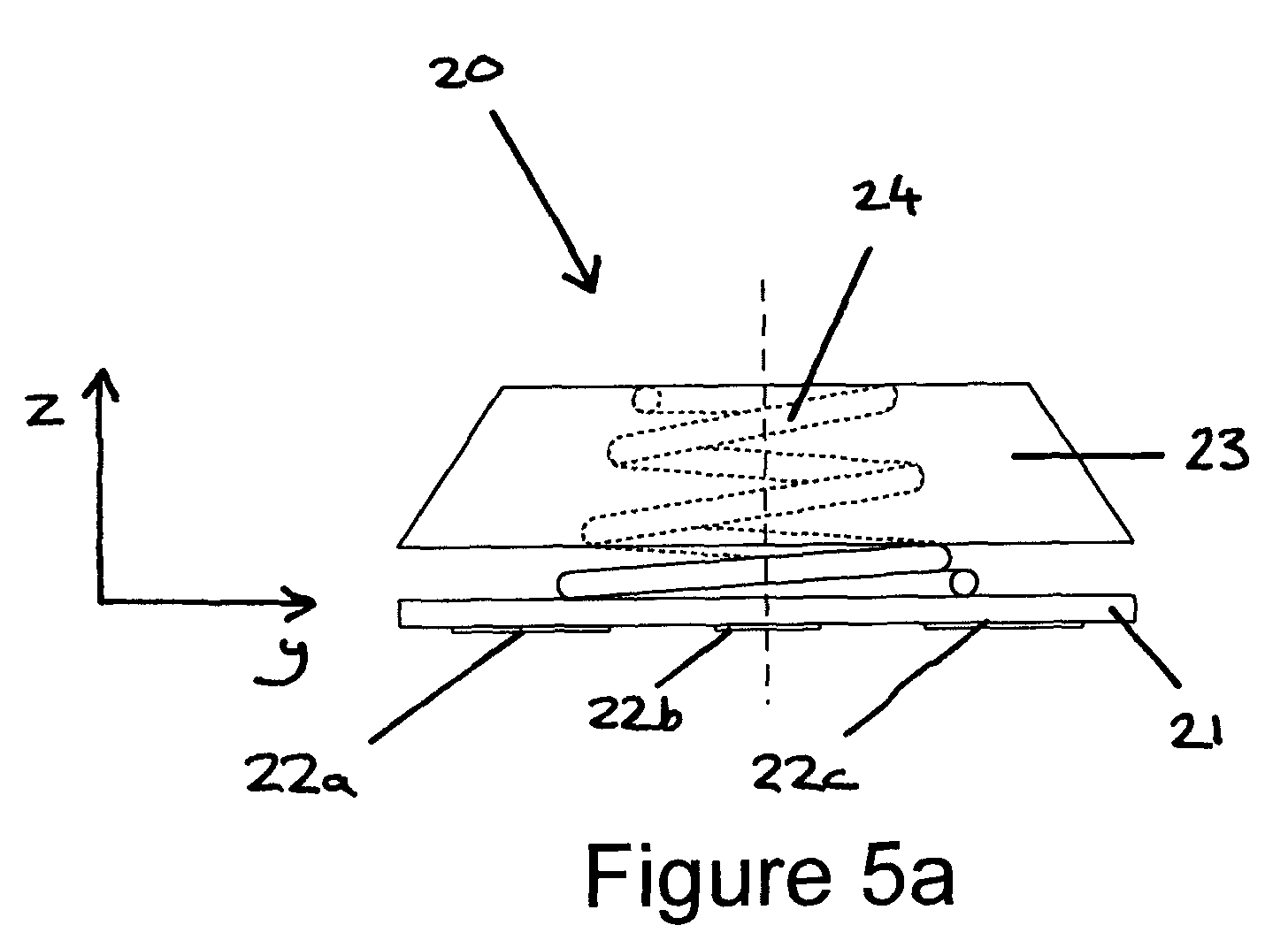
- Figure 5a is a side view of the embodiment shown in Figure 4a without force applied;
- Figure 5b is a side view of the embodiment shown in Figure 4a with force applied;
- Figure 6 is an exploded view of a third embodiment of the present invention and
- Figure 7 is an exploded view of a fourth embodiment of the present invention.
-
- Referring to Figures 1a and 1b, a first embodiment of a strain
gauge pointing device 1 is shown with and without aprotective cover 2 in place. Thepointing device 1 comprises a stick-type pointing device 3 comprising acontrol member 4 upstanding from atransducer structure 5 fitted to arigid plate 6 that is mounted on arubber base 7. Strain-sensitive resistors 5a, 5b, 5c, 5d are disposed within the body of thetransducer structure 5 in a well-known manner. In this example, therubber base 7 is located on a support substrate, in this example a printed circuit board (PCB) 8, which forms part of the electronic apparatus (not shown). Thepointing device 3 is electrically connected to the electronic apparatus though a flexible ribbon cable 9. Assembly of theresilient pointing device 1 is shown in more detail in Figures 2a and 2b. - Referring to Figures 2a and 2b, the stick-
type pointing device 3 is of a type well known in the art and is generally circular in plan view. Thepointing device 3 comprises an annular rim 10 having three equidistant legs 11 extending first radially, then downwardly, towards thePCB 8. Thepointing device 3 further comprises alobe 12 which rests on thePCB 8 and serves as a point about which thepointing device 3 may pivot. The legs 11 press-fit intoslots 12 formed in therigid plate 6. Therigid plate 6 is disc-shaped and is formed from durable plastic, although it will be appreciated that therigid plate 6 may also be formed from thin gauge steel or magnesium. - The
rigid plate 6 is bonded on top of therubber base 7. In this example, thebase 7 is generally bowl-shaped with amesa 13 in the centre. Themesa 13 has ahole 14 in the middle to receive thelobe 12. Thebase 7 has four posts 15, which are glued intoslots 16 in the PCB 8. It will be appreciated that therubber base 7 may be formed from other resilient materials and may have other shapes. For example, thebase 7 may be a rubber 'O'-ring, a keymat or a rubber disc. - It will be appreciated that other methods of attaching the
pointing device 3 to therigid plate 6 and therigid plate 6 to therubber base 7 may be used. For example, thepointing device 3 and therigid plate 6 may be a unitary structure. Therigid plate 6 and the rubber base may be glued or thermally bonded together. - Finally, the rubber
protective cover 2 is placed over thepositioning device 3 and secured by means of alip 17 over the edge of therigid plate 6. - The configuration shown in Figures 1 and 2 allows the
pointing device 3 to move relative to thePCB 8. This is explained in more detail with reference to Figure 3a and 3b. - Referring to Figures 1a, 3a and 3b, a
resilient pointing device 1 is shown with theprotective cover 2 removed. If no lateral force is applied to the free end of thecontrol member 4, thepointing device 3 sits with thecontrol member 4 substantially upright, as shown in Figure 3a. If a lateral force Fy is applied to the free end of thecontrol member 4 in the direction of the y-axis by the user's finger, thepointing device 3 and therigid plate 6 are tilted towards the y-axis, by an angle y from the z-axis. Therubber base 7 is deformed, with a leadingside 18 being downwardly compressed between therigid plate 6 and thePCB 8 and a trailingside 19 being upwardly stretched by therigid plate 6 from thePCB 8, as shown in Figure 3b. Thebase 7 resists this deformation and so the user feels resistance against their finger. As the user applies greater lateral force Fy by pressing harder, the angle of tilt y is increased, deformation is increased and so resistance to the applied force Fy is also increased. Therefore, the user will experience positive feedback. If the user applies a very large lateral force Fy, thepointing device 3 and therigid plate 6 are tilted sufficiently that the leading edge of therigid plate 6 presses against thePCB 8, thus preventing further tilting. - Similarly, if a lateral force Fx is applied parallel to the free end of the
control member 4 in the direction of the x-axis, thepointing device 3 is tilted towards the x-axis. - Thus, the
pointing device 3 may be tilted from z-axis in any direction in the x-y plane. Thus, the user is able to navigate theresilient pointing device 1 through 360° in the x-y plane and move an object, such as a cursor, around a display. - This configuration has the advantage that, as a larger force is applied to the
pointing device 3 and the cursor accelerates, the user feels greater resistance from thepointing device 3. This response from thepointing stick 3 feels more intuitive and the user finds it easier to control the movement of the cursor. It will be appreciated that characteristics of therubber base 7, such as its elasticity, may be tailored to the electronic apparatus and its intended application. - Referring to Figures 4a and 4b, a second embodiment of a
pointing device 20 is shown. Thesecond pointing device 20 comprises astrain gauge element 21 to the underside of which are mounted strain-sensitive resistors strain gauge element 21 is a ceramic cruciform of a type well known in the art. Thepointing device 20 further comprises anactuator 23 to which a user can apply a force using a finger or thumb. In this example, theactuator 23 is a button made of durable plastic, although other materials may be used. A force applied to theactuator 23 is transmitted to thestrain gauge element 21 via aresilient member 24, such as a coil spring. The coil string may be made from metal or plastic. Theresilient member 24 is bonded to thestrain gauge element 21. It will be appreciated that if the coil spring is used, it may be mounted to thestrain gauge element 21 at one end of the spring or along at least part of coil. Theresilient member 24 may be bonded, glued or clipped to thestrain gauge element 21. Similarly, the coil spring may be bonded, glued, moulded into or clipped to theactuator 23 at its other end. The strain-gauge element 21 may for part of or be mounted to a substrate, such as a PCB. - When assembled, the arrangement shown in Figures 4a and 4b allows the user to apply lateral and vertical forces to the
actuator 23 using their finger or thumb and to feel the actuator 23 move. This is explained in more detail with reference to Figures 5a and 5b. - If no force is applied to the
actuator 23, it sits substantially level, as shown in Figure 5a. If an off-centre downward force Fz is applied substantially along the y-axis by the user's finger, the actuator 23 tilts towards the y-axis, as shown in Figure 5b. Thespring 24 is bent and resists movement. The user feels the actuator 23 move and resistance against their finger. Thespring 24 induces strain in the strain-gauge element 21, which is measured by the strain-sensitive resistors actuator 23 moves even more. The amount of movement and the degree of resistance felt by the user may be adjusted using springs with different spring rates. - The
second pointing device 20 may be tilted in any direction in the x-y plane, which may be used to navigate an object, such as a cursor around a display. - The arrangement shown in Figure 4a and 4b may also be used to detect application of an on-centre downward force. If the user applies an on-centre downward force, the
spring 24 may be compressed and this downward movement may be felt by the user. The strain-gauge element 21 may be configured to detect this centrally applied force. This may be used for example to select objects using the navigable object. Alternatively, a separate switch (not shown) may be used to detect downward movement. - Referring to Figures 6, a third embodiment of a
pointing device 25 is shown. Thethird pointing device 25 is similar to thesecond device 20 except that aresilient frame 26 is used instead of a coil spring. Theframe 26 may be made from metal, plastic or rubber. - Referring to Figure 7, a fourth embodiment of a resilient pointing device 27 is shown. In the fourth pointing device 27, the actuator and the resilient member form a
unitary structure 28. - It will be appreciated that the invention can be used in relation to any sort of electronic apparatus, both portable and non-portable. This may include mobile telephone handsets and lap top computers.
- It will be appreciated that many modifications may be made. For example, the base and rigid plate need not be circular in plan view, but may be polygonal, especially regularly polygonal.
Claims (23)
- A control device for converting applied force into electrical signals for electronic apparatus, the device comprising a control member (4) for manipulation by a user, a strain sensor (5) to detect force applied to the control member by the user and resilient means (7) to permit movement of the control member and provide feedback to the user.
- A control device according to claim 1, wherein the control member and strain sensor are arranged as a moveable pointing device which is supported by the resilient means, the resilient means being configured to resist movement of the pointing device.
- A device according to claim 2, wherein a rigid plate is disposed between the pointing device and the resilient means.
- A device according to claim 2 or 3, further including a support substrate, the resilient means being mounted on the support substrate and the pointing device being mounted on the resilient means.
- A device according to claim 1, wherein the resilient means is arranged so as to transmit force from the control member to the strain sensor.
- A device according to claim 5, wherein the resilient means is disposed between the control member and the strain sensor.
- A device according to claim 5, wherein the resilient means and the control member are configured as a unitary member.
- A device according to any preceding claim, wherein the resilient means is compressible.
- A device according to any preceding claim, wherein the resilient means is stretchable.
- A device according to any preceding claim, wherein the resilient means is cylindrical.
- A device according to any preceding claim, wherein the resilient means is toroidal.
- A device according to any preceding claim, wherein the resilient means is a helical.
- A device according to any preceding claim, wherein the resilient means comprises a supportive cup.
- A device according to any preceding claim, wherein the resilient means is made of rubber.
- A device according to any one of claims 1 to 13, wherein the resilient means is made of metal.
- A device according to any one of claims 1 to 13, wherein the resilient means is made of plastic.
- A device according to any preceding claim wherein the strain sensor comprises a resistive element.
- Electronic apparatus including a control device according to any preceding claim.
- Apparatus according to claim 18 including a display device, the control device being configured to control operation of the display device.
- Apparatus according to claim 18 or 19, which is portable.
- Apparatus according to claim 20 wherein said electronic apparatus is a mobile telephone handset.
- Apparatus according to claim 20 or 21 wherein said electronic apparatus is a computer.
- A method of fabricating a control device for converting applied force into electrical signals for electronic apparatus, the method comprising providing a control member for manipulation by a user, providing a strain sensor to detect force applied to the control member and providing resilient means to permit movement of the control member and provide feedback to the user.
Applications Claiming Priority (2)
| Application Number | Priority Date | Filing Date | Title |
|---|---|---|---|
| GB0023475A GB2367113A (en) | 2000-09-25 | 2000-09-25 | A control device having a strain sensor and a resilient means |
| GB0023475 | 2000-09-25 |
Publications (1)
| Publication Number | Publication Date |
|---|---|
| EP1191418A1 true EP1191418A1 (en) | 2002-03-27 |
Family
ID=9900082
Family Applications (1)
| Application Number | Title | Priority Date | Filing Date |
|---|---|---|---|
| EP01306834A Withdrawn EP1191418A1 (en) | 2000-09-25 | 2001-08-10 | Control device |
Country Status (4)
| Country | Link |
|---|---|
| US (1) | US20020054015A1 (en) |
| EP (1) | EP1191418A1 (en) |
| JP (1) | JP2002175154A (en) |
| GB (1) | GB2367113A (en) |
Cited By (1)
| Publication number | Priority date | Publication date | Assignee | Title |
|---|---|---|---|---|
| WO2012085363A1 (en) * | 2010-12-22 | 2012-06-28 | Valeo Systemes Thermiques | Multifunction control button and device |
Families Citing this family (10)
| Publication number | Priority date | Publication date | Assignee | Title |
|---|---|---|---|---|
| US7567232B2 (en) * | 2001-03-09 | 2009-07-28 | Immersion Corporation | Method of using tactile feedback to deliver silent status information to a user of an electronic device |
| CA2409915C (en) * | 2002-10-29 | 2012-01-03 | Research In Motion Limited | Electronic device having keyboard for thumb typing |
| US7170487B2 (en) * | 2003-01-20 | 2007-01-30 | Murata Manufacturing Co., Ltd. | Pointing device and method of producing the same |
| JP4188778B2 (en) * | 2003-08-04 | 2008-11-26 | アルプス電気株式会社 | Input device |
| JP4359478B2 (en) * | 2003-10-14 | 2009-11-04 | アルプス電気株式会社 | Joystick type switch device |
| DE102008017832B4 (en) * | 2008-04-08 | 2011-06-16 | Siemens Aktiengesellschaft | Input device for controlling elements of graphic user interfaces |
| CN103415276B (en) * | 2011-02-28 | 2015-05-20 | 村田机械株式会社 | Upper limb exercising device |
| JP2015102953A (en) * | 2013-11-22 | 2015-06-04 | 株式会社デンソー | Operation input device |
| US10372212B2 (en) | 2015-05-29 | 2019-08-06 | Google Llc | Techniques for simulated physical interaction between users via their mobile computing devices |
| JP6471065B2 (en) * | 2015-08-05 | 2019-02-13 | アルプス電気株式会社 | Input device |
Citations (9)
| Publication number | Priority date | Publication date | Assignee | Title |
|---|---|---|---|---|
| US3447766A (en) * | 1967-02-14 | 1969-06-03 | Bendix Corp | Control stick with solid state sensors |
| GB2283080A (en) * | 1993-10-22 | 1995-04-26 | Central Research Lab Ltd | Computer input mouse. |
| EP0681261A1 (en) | 1994-04-29 | 1995-11-08 | International Business Machines Corporation | Pointing device transducer using thick film resistor strain sensors |
| US5640178A (en) | 1994-09-16 | 1997-06-17 | Fujitsu Limited | Pointing device |
| US5659334A (en) | 1993-12-15 | 1997-08-19 | Interlink Electronics, Inc. | Force-sensing pointing device |
| EP0844584A2 (en) | 1996-11-25 | 1998-05-27 | CTS Corporation | Pointing device |
| US5767840A (en) * | 1996-06-28 | 1998-06-16 | International Business Machines Corporation | Six-degrees-of-freedom movement sensor having strain gauge mechanical supports |
| EP0869343A1 (en) * | 1997-04-04 | 1998-10-07 | Matsushita Electric Industrial Co., Ltd. | Load sensor and pointing equipment incorporating the same |
| EP0917330A2 (en) * | 1997-11-17 | 1999-05-19 | Nec Corporation | Portable communication apparatus |
Family Cites Families (5)
| Publication number | Priority date | Publication date | Assignee | Title |
|---|---|---|---|---|
| FR2659789B1 (en) * | 1990-03-15 | 1996-09-27 | Sextant Avionique | CONSTRAINED GAUGE MANIPULATOR. |
| DE4209668A1 (en) * | 1992-03-25 | 1993-09-30 | Rexroth Mannesmann Gmbh | Joystick unit for remote control of hydraulic systems e.g.pumps or motors - has strain gauge strips bonded to leaf spring within housing generating output proportional to deflection |
| NL9300067A (en) * | 1993-01-14 | 1994-08-01 | Protonic Beheer B V | Device to control the cursor on the monitor of a computer or the like |
| US5982355A (en) * | 1993-11-05 | 1999-11-09 | Jaeger; Denny | Multiple purpose controls for electrical systems |
| JP3247630B2 (en) * | 1997-03-07 | 2002-01-21 | インターナショナル・ビジネス・マシーンズ・コーポレーション | Pointing device, portable information processing apparatus, and method of operating information processing apparatus |
-
2000
- 2000-09-25 GB GB0023475A patent/GB2367113A/en not_active Withdrawn
-
2001
- 2001-08-10 EP EP01306834A patent/EP1191418A1/en not_active Withdrawn
- 2001-08-14 US US09/929,820 patent/US20020054015A1/en not_active Abandoned
- 2001-09-14 JP JP2001280517A patent/JP2002175154A/en not_active Withdrawn
Patent Citations (9)
| Publication number | Priority date | Publication date | Assignee | Title |
|---|---|---|---|---|
| US3447766A (en) * | 1967-02-14 | 1969-06-03 | Bendix Corp | Control stick with solid state sensors |
| GB2283080A (en) * | 1993-10-22 | 1995-04-26 | Central Research Lab Ltd | Computer input mouse. |
| US5659334A (en) | 1993-12-15 | 1997-08-19 | Interlink Electronics, Inc. | Force-sensing pointing device |
| EP0681261A1 (en) | 1994-04-29 | 1995-11-08 | International Business Machines Corporation | Pointing device transducer using thick film resistor strain sensors |
| US5640178A (en) | 1994-09-16 | 1997-06-17 | Fujitsu Limited | Pointing device |
| US5767840A (en) * | 1996-06-28 | 1998-06-16 | International Business Machines Corporation | Six-degrees-of-freedom movement sensor having strain gauge mechanical supports |
| EP0844584A2 (en) | 1996-11-25 | 1998-05-27 | CTS Corporation | Pointing device |
| EP0869343A1 (en) * | 1997-04-04 | 1998-10-07 | Matsushita Electric Industrial Co., Ltd. | Load sensor and pointing equipment incorporating the same |
| EP0917330A2 (en) * | 1997-11-17 | 1999-05-19 | Nec Corporation | Portable communication apparatus |
Cited By (2)
| Publication number | Priority date | Publication date | Assignee | Title |
|---|---|---|---|---|
| WO2012085363A1 (en) * | 2010-12-22 | 2012-06-28 | Valeo Systemes Thermiques | Multifunction control button and device |
| FR2969774A1 (en) * | 2010-12-22 | 2012-06-29 | Valeo Systemes Thermiques | BUTTON AND MULTIFUNCTION CONTROL DEVICE |
Also Published As
| Publication number | Publication date |
|---|---|
| GB0023475D0 (en) | 2000-11-08 |
| US20020054015A1 (en) | 2002-05-09 |
| GB2367113A (en) | 2002-03-27 |
| JP2002175154A (en) | 2002-06-21 |
Similar Documents
| Publication | Publication Date | Title |
|---|---|---|
| US6343991B1 (en) | Game control with analog pressure sensor | |
| EP1168234B1 (en) | Coordinate input apparatus | |
| US6628266B1 (en) | Joystick controller | |
| US6102802A (en) | Game controller with analog pressure sensor(s) | |
| US5670955A (en) | Method and apparatus for generating directional and force vector in an input device | |
| US7534973B2 (en) | Device for detecting a mechanical actuation of an input element by using digital technology, and method for processing and converting the digital input signal into commands for controlling a load | |
| EP0759199B1 (en) | Force-sensing pointing device | |
| US9612674B2 (en) | Movable track pad with added functionality | |
| US5790102A (en) | Pressure sensitive computer mouse | |
| US5751274A (en) | Foot-operable cursor control device | |
| EP1193643A1 (en) | Control device | |
| US7684953B2 (en) | Systems using variable resistance zones and stops for generating inputs to an electronic device | |
| US20020054015A1 (en) | Control device | |
| US20110018798A1 (en) | Cursor control device | |
| US5894301A (en) | Collar mounted pointing stick | |
| US7402764B2 (en) | Multi-functional touch actuator in electronic devices | |
| AU4708800A (en) | Hand-held control with analog pressure sensor(s) | |
| WO2003005334A2 (en) | Controller with tactile feedback | |
| JPH10333822A (en) | Coordinate input device | |
| JPH0784717A (en) | pointing device | |
| US9235274B1 (en) | Low-profile or ultra-thin navigation pointing or haptic feedback device | |
| JP2005228040A (en) | Capacitive force sensor operation mechanism | |
| JPH06295641A (en) | pointing device | |
| JPH11338630A (en) | Capacitive device |
Legal Events
| Date | Code | Title | Description |
|---|---|---|---|
| PUAI | Public reference made under article 153(3) epc to a published international application that has entered the european phase |
Free format text: ORIGINAL CODE: 0009012 |
|
| AK | Designated contracting states |
Kind code of ref document: A1 Designated state(s): DE FR GB IT Kind code of ref document: A1 Designated state(s): AT BE CH CY DE DK ES FI FR GB GR IE IT LI LU MC NL PT SE TR |
|
| AX | Request for extension of the european patent |
Free format text: AL;LT;LV;MK;RO;SI |
|
| 17P | Request for examination filed |
Effective date: 20020814 |
|
| AKX | Designation fees paid |
Free format text: DE FR GB IT |
|
| STAA | Information on the status of an ep patent application or granted ep patent |
Free format text: STATUS: THE APPLICATION HAS BEEN WITHDRAWN |
|
| 18W | Application withdrawn |
Effective date: 20030422 |