EP1191340A1 - Field distribution measuring method and device - Google Patents
Field distribution measuring method and device Download PDFInfo
- Publication number
- EP1191340A1 EP1191340A1 EP01921903A EP01921903A EP1191340A1 EP 1191340 A1 EP1191340 A1 EP 1191340A1 EP 01921903 A EP01921903 A EP 01921903A EP 01921903 A EP01921903 A EP 01921903A EP 1191340 A1 EP1191340 A1 EP 1191340A1
- Authority
- EP
- European Patent Office
- Prior art keywords
- probe
- data
- sampling points
- shift amount
- field distribution
- Prior art date
- Legal status (The legal status is an assumption and is not a legal conclusion. Google has not performed a legal analysis and makes no representation as to the accuracy of the status listed.)
- Withdrawn
Links
Images




Classifications
-
- G—PHYSICS
- G01—MEASURING; TESTING
- G01R—MEASURING ELECTRIC VARIABLES; MEASURING MAGNETIC VARIABLES
- G01R29/00—Arrangements for measuring or indicating electric quantities not covered by groups G01R19/00 - G01R27/00
- G01R29/08—Measuring electromagnetic field characteristics
- G01R29/0864—Measuring electromagnetic field characteristics characterised by constructional or functional features
- G01R29/0892—Details related to signal analysis or treatment; presenting results, e.g. displays; measuring specific signal features other than field strength, e.g. polarisation, field modes, phase, envelope, maximum value
-
- G—PHYSICS
- G01—MEASURING; TESTING
- G01R—MEASURING ELECTRIC VARIABLES; MEASURING MAGNETIC VARIABLES
- G01R33/00—Arrangements or instruments for measuring magnetic variables
- G01R33/02—Measuring direction or magnitude of magnetic fields or magnetic flux
- G01R33/10—Plotting field distribution ; Measuring field distribution
Definitions
- the present invention relates to a field distribution measuring method and apparatus for measuring a distribution of an electric field or a magnetic field by a probe sweeping, more specifically, to a field distribution measuring method and apparatus which can eliminate measured noises generated due to offsets between probe sweeping positions and measuring timings.
- Small antenna directivity evaluation apparatuses and electromagnetic wave monitoring visualizing apparatuses must measure two-dimensional distributions of electric fields or magnetic fields. These apparatuses have conventionally used a field measurement method in which a probe sweeps two-dimensionally to measure two-dimensional distributions of electric fields or magnetic fields.
- a field distribution measurement screen 100 which defines an area in which electric fields or magnetic fields are to be measured includes a probe 102 for detecting electric fields or magnetic fields.
- the probe 102 is connected to a probe sweep control unit 104 and can sweep in the x-axial direction and the y-axial direction.
- the probe 102 is connected to a measuring unit 106 which measures electric fields or magnetic fields, based on signals from the probe 102.
- the probe sweep control unit 104 outputs a measurement trigger signal corresponding to a position of the probe 102 and supplies the measurement trigger signal to the measuring unit 106.
- Data F of the electric fields or magnetic fields measured by the measuring unit 106 are recorded in a buffer memory 108 together with position information supplied by the probe sweep control unit 104.
- the buffer memory 108 is connected to a computing/display unit 110 which develops and display in two-dimensional plane measured data stored in the buffer memory 108.
- a field distribution is measured by the probe 102 sweeping the field distribution measurement screen 100 while electric fields or magnetic fields being measured on the field distribution measurement screen 100, and measured electric fields or magnetic fields are processed together with position information of the probe 102.
- the probe 102 continuously sweeps the field distribution measurement screen without pausing at each sampling point (measuring point) so that the probe 102 can sweep without loss for maximum measurement throughput.
- the probe 102 is moves in the positive direction along the x-axis, then moved by a prescribed value in the positive direction along the y-axis, next moved in the negative direction along the x-axis, then moved by a prescribed value in the positive direction along the y-axis, and then moved in the positive direction along the x-axis.
- the probe 102 repeats these motions to be moved so as to sweep substantially all the surface of the field distribution measurement screen (hereinafter call such sweep "zigzag sweep").
- the probe sweep control unit 104 outputs measurement trigger signals corresponding to positions of the probe 102 while the probe 102 is sweeping the field distribution measurement screen 100.
- a plurality of x coordinates are set in advance, spaced equidistantly from each other along the x-axis, and when an x coordinate of a position of the probe 102 comes to each of the set x-coordinates, the probe sweep control unit 104 outputs a measurement trigger signal.
- the measurement trigger signals are supplied to the measuring unit 106.
- the measuring unit 106 judges a signal detected by the probe 102 when the measuring unit 106 received the measurement trigger signal to be information of electric fields or magnetic fields, and measures the electric fields or magnetic fields, based on the signal outputted by the probe 102.
- Data of electric fields or magnetic fields thus measured are stored by the buffer memory 108 together with position information (coordinates (x,y)) of the probe outputted by the prove sweep control unit.
- the data stored by the buffer memory 108 are developed on two-dimensional plane by the computing/display unit 110, and a two-dimensional field distribution of electric fields or magnetic fields can be provided.
- a deviation amount of the sampling points between the odd number-th line and the even number-th line is 2 ⁇ v ⁇ t d [m] by which x axial sampling positions on both lines deviates from each other for the same trigger point when a sweeping velocity of the probe is v [m/s], and a delay time is t d [sec].
- An object of the present invention is to provide a field distribution measuring method and apparatus for measuring a distribution of electric fields or magnetic fields by continuously sweeping a probe, wherein measuring noises generated due to offsets between sweeping positions of the probe and measuring timings can be removed.
- the above-described object can be achieved by a field distribution measuring method for measuring an electric field or a magnetic field by a probe measuring at a plurality of sampling points while continuously sweeping, wherein a shift amount of the sampling points is computed, based on a spurious spectrum generated by a displacement between a position of the probe and a measuring timing, and a distribution of the electric field or the magnetic field is measured in consideration of the shift amount.
- the method comprises: storing a plurality of measured data measured by the probe sweeping in a first direction together with position information of the probe as reference data; storing a plurality of measured data measured by the probe sweeping in a second direction opposite to the first direction together with position information of the probe as adjustment data; interpolating the adjustment data to compute interpolated data with data between the sampling points interpolated; computing spatial frequency power spectra for the reference data and the interpolated data; and computing the shift amount of the sampling points, based on the spatial frequency power spectra.
- the shift amount of the sampling points is computed based on an accumulated value of the spatial frequency power spectra.
- the shift amount of the sampling points is judged, based on a point where the accumulated value of the spatial frequency power spectra is below a prescribed value.
- the shift amount of the sampling points is judged, based on a point where the accumulated value of the spatial frequency power spectra is minimum.
- the shift amount of the sampling points is computed in consideration of acceleration and deceleration of the probe.
- the probe sweeps on a two-dimensional plane.
- a field distribution measuring apparatus comprising: a probe for detecting an electric field or a magnetic field at a plurality of sampling points while continuously sweeping on a plane or in a space; measuring unit for measuring the electric field or the magnetic field detected by the probe; storing unit for storing data of the electric field or the magnetic field measured by the measuring unit together with position data of the probe; data processing unit for computing a shift amount of sampling points generated by a displacement between a position of the probe and a measuring timing, based on data stored in the storing unit; and computing unit for computing a spatial distribution of the electric field or the magnetic field detected by the probe, in consideration of the shift amount of the sampling points computed by the data processing unit.
- the data processing unit computes the shift amount of the sampling points, based on a spurious spectrum generated by the displacement between the position of the probe and the measuring timing.
- a field distribution measuring method for measuring a spatial distribution of an electric field or a magnetic field at a plurality of sampling points by the probe continuously sweeping the sampling points, in which, based on spurious spectra generated by offsets between positions of the probe and measuring timings, a shift amount of the sampling points is computed, and, taking into account the shift amount, a distribution of electric fields or magnetic fields is measured.
- FIG. 1 is a block diagram of the field distribution measuring method and apparatus according to the present embodiment.
- FIG. 2 is a flow chart of a data processing method of the field distribution measuring method according to the present embodiment.
- FIG. 3 is a graph of relationships between accumulated values of frequency power spectra and sampling shift amounts.
- a probe 12 for detecting electric fields or magnetic fields is provided on a field distribution measurement screen 10.
- the probe 12 is connected to a probe sweep control unit 20 and can sweep in the x-axis direction and in the y-axis direction within the field distribution measurement screen 10.
- the probe 12 is connected to a measuring unit 30 which measures electric fields or magnetic fields, based on signals from the probe 12.
- the probe sweep control unit 20 generates measurement trigger signals corresponding to positions of the probe to input the measurement trigger signals to the measuring unit 30.
- Data F 0 of an electric field or a magnetic field measured by the measuring unit 30 can be stored in the buffer memory 40 together with position information supplied from the probe sweep control unit 20.
- the buffer memory 40 is connected to a data processing unit 50 which removes sampling noises of measured data stored in the buffer memory 40.
- the data processing unit 50 is connected to a computing/display unit 60 which develops sampling noise removed data processed by the data processing unit 50 to display the data on two-dimensional plane.
- the data processing unit 50 comprises an interpolating unit 52 which interpolates measured data stored in the buffer memory 40, a shift amount computing unit 54 which computes a shift amount of sampling points, based on spatial frequency spectra for the measured data and interpolated data, a data correcting unit 56 which corrects the measured data, based on a computed shift amount, and a sampling noise removed data computing unit 58 which computes sampling noise removed data, based on the measured data and the corrected data.
- the field distribution measuring apparatus is characterized in that the data processing unit 50 for removing sampling noises from measured data is provided between the buffer memory 40 and the computing/display unit 60.
- the field distribution measuring apparatus having such constitution can remove sampling noises to thereby measure a correct two-dimensional field distribution.
- the field distribution measurement screen 10 is positioned opposed to an object-to-be-observed.
- the field distribution measurement screen 10 is set so as to provide a sampling interval sufficiently small for a change period of field distributions to be measured.
- the field distribution measurement screen 10 is set to hold ⁇ » L 1 /N, ⁇ » L 2 /M where a wavelength of electromagnetic waves or others to be measured is ⁇ , a length of the field distribution measurement screen in the x-axis direction is L 1 , a length of the field distribution measurement screen in the y-axis direction is L 2 , a number of sampling points in the x-axis direction is N, and a number of sampling points in the y-axis direction is M.
- the probe 12 is caused to sweep by the probe control unit 20 to detect electric fields or magnetic fields at positions of the probe 12 on the field distribution screen 10.
- the probe 12 sweeps continuously zigzag on the field distribution measurement screen 10 without pausing at each sampling point (measuring point).
- the probe sweep control unit 20 controls the probe 12 and outputs measurement trigger signals corresponding to positions of the probe 12. For example, a plurality of x coordinates are set equidistantly along the x-axis, and every time that an x coordinate of a position where the probe 12 is present is moved to each set point, the probe sweep control unit 20 outputs a measurement trigger signal.
- the measurement trigger signal is supplied to the measuring unit 30.
- the measuring unit 30 judges a signal detected by the probe 12 when the measuring unit 30 received the measurement trigger signal to be information of an electric field or a magnetic field at the sampling point and, based on an output signal of the probe 12 at this time, carries out the measurement of the electric field or the magnetic field.
- a delay time is present between the detection of the measurement trigger signal and the output of a measured value.
- the probe 12 does not pause at each sampling point but continuously sweeps zigzag for higher measuring throughputs. Accordingly, an x coordinate of the probe 12 at the time of outputting a measurement trigger signal is displaced from an x coordinate of the probe 12 at the time of the actual measurement.
- a shift direction of coordinates in an odd number-th line on the y-axis is opposite to that of coordinates in an even number-th line on the y-axis. That is, as shown in FIG. 7, in an odd number-th line on the y-axis, where the probe is moved along the x-axis in the positive direction, sampling points shift in the positive direction (circled in FIG.7). Oppositely, in an odd number-th line on the y-axis, where the probe is moved along the x-axis in the negative direction, sampling points shift also in the negative direction (crossed in FIG. 7).
- a deviation amount of the sampling points for the same measurement trigger point between the odd-number-th line and the even number-th line is 2 ⁇ v ⁇ t d [m] where a probe sweeping velocity is represented by v [m/s], and a delay time is represented by t d [sec].
- the thus-measured data F 0 of electric fields or magnetic fields are stored in the buffer memory 40 as measured data F 0 (x,y) together with position information of the probe 12 (coordinates (x,y)) outputted by the probe sweep control unit 20.
- the measured data F 0 (x,y) are divided into a plurality of groups to make one group reference sampling data and the other group adjustment data.
- the measured data are divided into data of an odd number-th line on the y-axis, where the probe is moved along the x-axis in the positive direction (odd number-th line data F 0 (x,y o )), and into data of an even number-th line on the y-axis, where the probe is moved along the x-axis in the negative direction (even number-th line data F 0 (x,y e )), and the even number-th line data and the odd number-th line data are respectively stored in the buffer memory 40.
- the odd number-th line data F 0 (x,y o ) is the reference sampling data
- the odd number-th line data F 0 (x,y e ) is the adjustment data.
- x is up to N+1 for the later spline interpolation. When no N+1-th data is absent, the N-1-th data can be used as the N+1-th data.
- the data processing unit 50 computes, based on the measured data F 0 (x,y), sampling noise removed data F(x,y) with sampling noises removed (see FIG. 2).
- the interpolating unit 52 performs spline interpolation on the adjustment data stored in the buffer memory 40 to compute interpolated data.
- the spline interpolation is performed on the even number-th line data F 0 (x,y e ), which is the adjustment data, with respect to the x-axis direction to compute interpolated data F 0 '(x',y e ) (step S11).
- the spline interpolation an interval between each of the sampling points and its adjacent one is divided in k, and data at the k points are interpolated.
- the data F 0 (x,y), which is a complex number, is divided into a real number and an imaginary number to be vector curves on complex planes and is subjected to spline interpolation for the many-valued function.
- the spline interpolation is detailed in, e.g., D. F. Rogers and J. A. Adams, "Mathematical Elements for Computer Graphics", McGraw-Hill, 1876.
- a shift amount of the sampling points are computed by the shift amount computing unit 54, based on spacial frequency power spectra for the reference sampling data and interpolated data.
- dx represents a parameter indicative of a shift amount of a sampling point along the x-axis.
- dx -k+1, -k+2, ..., k-1, k.
- x' of the interpolated data F 0 '(x',y e ) is substituted by k ⁇ x+dx so as to give a spatial frequency power spectra in consideration of shifts of the sampling points.
- f y M/2
- a spatial frequency power spectrum can be given by only adding odd number-th line data F 0 (x,y o ), and interpolated data of even number-th line data F 0 '(k ⁇ x+dx,y e ) which are given different signs.
- the accumulated value a dx is given because, depending on the position in the x-axis direction, the influence of shifts of the sampling point is small, which makes the re-sampling difficult.
- the accumulated value a dx is given, whereby the influence of shifts of the sampling points is averaged. Based on the accumulated value a dx , shifts of the sampling points can be accurately evaluated. An accumulated value a dx may not be essentially given when the case that the influence of shifts of the sampling points is large can be anticipated.
- FIG. 3 is a graph of one example of relationships between accumulated values a dx and shift amounts dx.
- an interpolation point number k is 10.
- an accumulated value a dx is minimum when the shift amount dx is about +7.
- the shift amount dx' is +7.
- the corrected data processing unit 56 corrects measured data, based on a shift amount computed by the shift amount computing unit 54 to compute corrected data.
- contents of even number-th line data F 0 (x,y e ) is substituted by a shift amount dx' given by the above-described search processing and interpolated data F 0 '(x',y e ) to compute even number-th line corrected data F 0 "(x,y e ). That is, the even number-th line corrected data F 0 "(x,y e ) is represented as follows (Step S13).
- sampling noise removed data computing unit 58 conduct re-sampling, based on the reference sampling data and the corrected data to compute sampling noise removed data.
- odd number-th line data F 0 (x,y o ) and even number-th line corrected data F 0 "(x,y e ) are synthetically substituted to be sampling noise removed data F(x,y) (step S14).
- the computing/display unit 60 develops the sampling noise removed data F(x,y) on the two-dimensional plane to thereby provide a two-dimensional field distribution of electric fields or magnetic fields.
- FIG. 4 is views of a field distribution of two-dimensional sweep measured data containing sampling noises, i.e., measured data F 0 (x,y) developed on the two-dimensional plane as they are. These data are of a current distribution of a mobile telephone of 1.5 GHz, which was measured by using a small-antenna directivity evaluating apparatus.
- FIG. 4A shows a plane distribution of amplitude data.
- FIG. 4B shows a plane distribution of phase data. The shown data copy the measured data. Points where amplitudes or phase are equal are interconnected to show the distribution.
- the rectangular portion at the center of the drawings indicates the body of the mobile telephone. The straight line extended from the rectangle indicates the antenna. As shown, in the two-dimensional images the distribution is disturbed in the x-axis direction, which apparently indicates occurrences of sampling point shifts.
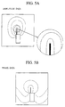
- FIG. 5 is views of a field distribution of two-dimensional sweep measured data with sampling noises removed by the algorithm of the present embodiment, i.e., sampling noise removed data F(x,y) developed on the two-dimensional plane.
- FIG. 5A is a plane distribution of amplitude data.
- FIG. 5B is a plane distribution of phase data. As shown, the distributions of these two-dimensional images are smooth, and it is seen that the measured data F 0 (x,y) have been properly corrected.
- the field distribution measuring method in which the probe is continuously moved, sweeping a plurality of sampling points, measuring electric fields or magnetic fields to thereby measure a spatial distribution of the electric fields or magnetic fields, wherein a displacement amount of a sampling point is judged based spurious spectra generated by the displacement between positions of the probe and timings of the measurement, and, in consideration of an amount of the displacement, a distribution of electric fields or magnetic fields is measured, whereby measuring noises generated by the displacement between probe positions and measuring timings can be properly removed.
- the field distribution measurement screen 10 is two-dimensional.
- the field distribution measurement screen 10 may be three-dimensional.
- the adjustment data have 2 or more groups.
- the adjustment parameters are 2 or more, and the spatial frequency power spectra for the evaluation are two or more dimensional.
- a shift amount dx of sampling points is constant.
- a shift amount may be a variable in consideration of acceleration of the sweep of the probe.
- dx may be a function of x, dx(x).
- Fourier transform is used for the evaluation of spatial frequency power spectra.
- Walsh transform or wavelet transform may be used.
- Spatial frequency power spectra may be subjected to window function to evaluate the spectra.
- a shift amount for minimizing an accumulated values of spatial frequency power spectra is utilized to remove measuring noises, but a shift amount for minimizing an accumulated value of spatial frequency power spectra may not be used.
- a shift amount for minimizing an accumulated value of spatial frequency power spectra is used as a most desirable state.
- the effect of the present invention is achieved by setting a shift amount dx at a value which makes an accumulated value of spatial frequency power spectra smaller than that without measuring noises removed.
- measuring noises may be removed by utilizing a shift amount which makes an accumulated value of spatial frequency power spectra below a prescribed value, e.g., below 1/10 of an accumulated value of spatial frequency power spectra without measuring noises removed.
- the field distribution measuring method and apparatus in measuring spatial distribution of electric fields or magnetic fields by the probe continuously sweeping, measuring at a plurality of sampling points, spurious spectra generated due to displacement between positions of the probe and measuring timings, a shift amount of the sampling is computed, and a distribution of electric fields or magnetic fields is measured in consideration of the shift amount, whereby measuring noises generated due to offsets of sweeping positions of the probe and the measuring timings can be properly removed.
- the present invention is useful as field distribution methods and apparatuses for measuring two-dimension distributions of electric fields or magnetic fields of small-antenna directivity evaluating apparatuses, electromagnetic wave monitor visualizing apparatuses, etc.
Landscapes
- Physics & Mathematics (AREA)
- General Physics & Mathematics (AREA)
- Electromagnetism (AREA)
- Condensed Matter Physics & Semiconductors (AREA)
- Measuring Magnetic Variables (AREA)
Abstract
Description

Claims (10)
- A field distribution measuring method for measuring an electric field or a magnetic field by a probe measuring at a plurality of sampling points while continuously sweeping, wherein
a shift amount of the sampling points is computed, based on a spurious spectrum generated by a displacement between a position of the probe and a measuring timing, and a distribution of the electric field or the magnetic field is measured in consideration of the shift amount. - A field distribution measuring method according to claim 1, comprising:storing a plurality of measured data measured by the probe sweeping in a first direction together with position information of the probe as reference data;storing a plurality of measured data measured by the probe sweeping in a second direction opposite to the first direction together with position information of the probe as adjustment data;interpolating the adjustment data to compute interpolated data with data between the sampling points interpolated;computing spatial frequency power spectra for the reference data and the interpolated data; andcomputing the shift amount of the sampling points, based on the spatial frequency power spectra.
- A field distribution measuring method according to claim 2, wherein
the shift amount of the sampling points is computed based on an accumulated value of the spatial frequency power spectra. - A field distribution measuring method according to claim 3, wherein
the shift amount of the sampling points is judged, based on a point where the accumulated value of the spatial frequency power spectra is below a prescribed value. - A field distribution measuring method according to claim 3 or 4, wherein
the shift amount of the sampling points is judged, based on a point where the accumulated value of the spatial frequency power spectra is minimum. - A field distribution measuring method according to any one of claims 1 to 5, wherein
the shift amount of the sampling points is computed in consideration of acceleration and deceleration of the probe. - A field distribution measuring method according to any one of claims 1 to 6, wherein
the probe sweeps on a two-dimensional plane. - A field distribution measuring method according to any one of claims 1 to 6, wherein
the probe sweep in a three-dimensional space. - A field distribution measuring apparatus comprising:a probe for detecting an electric field or a magnetic field at a plurality of sampling points while continuously sweeping on a plane or in a space;measuring unit for measuring the electric field or the magnetic field detected by the probe;storing unit for storing data of the electric field or the magnetic field measured by the measuring unit together with position data of the probe;data processing unit for computing a shift amount of sampling points generated by a displacement between a position of the probe and a measuring timing, based on data stored in the storing unit; andcomputing unit for computing a spatial distribution of the electric field or the magnetic field detected by the probe, in consideration of the shift amount of the sampling points computed by the data processing unit.
- A field distribution measuring apparatus according to claim 9, wherein
the data processing unit computes the shift amount of the sampling points, based on a spurious spectrum generated by the displacement between the position of the probe and the measuring timing.
Applications Claiming Priority (3)
| Application Number | Priority Date | Filing Date | Title |
|---|---|---|---|
| JP2000129802A JP2001311756A (en) | 2000-04-28 | 2000-04-28 | Field distribution measurement method and apparatus |
| JP2000129802 | 2000-04-28 | ||
| PCT/JP2001/003344 WO2001084165A1 (en) | 2000-04-28 | 2001-04-19 | Field distribution measuring method and device |
Publications (2)
| Publication Number | Publication Date |
|---|---|
| EP1191340A1 true EP1191340A1 (en) | 2002-03-27 |
| EP1191340A4 EP1191340A4 (en) | 2008-08-20 |
Family
ID=18639017
Family Applications (1)
| Application Number | Title | Priority Date | Filing Date |
|---|---|---|---|
| EP01921903A Withdrawn EP1191340A4 (en) | 2000-04-28 | 2001-04-19 | Field distribution measuring method and device |
Country Status (8)
| Country | Link |
|---|---|
| US (1) | US6804617B2 (en) |
| EP (1) | EP1191340A4 (en) |
| JP (1) | JP2001311756A (en) |
| KR (1) | KR100608175B1 (en) |
| CN (1) | CN1246701C (en) |
| CA (1) | CA2377959A1 (en) |
| TW (1) | TW544519B (en) |
| WO (1) | WO2001084165A1 (en) |
Cited By (1)
| Publication number | Priority date | Publication date | Assignee | Title |
|---|---|---|---|---|
| EP3483615A1 (en) * | 2017-11-10 | 2019-05-15 | Rohde & Schwarz GmbH & Co. KG | Measuring system and measuring method for over the air measurement of electric field potential |
Families Citing this family (18)
| Publication number | Priority date | Publication date | Assignee | Title |
|---|---|---|---|---|
| JP2006003229A (en) * | 2004-06-17 | 2006-01-05 | Ntt Docomo Inc | Measuring position control device and method |
| JP4680572B2 (en) * | 2004-11-09 | 2011-05-11 | 株式会社日立製作所 | Magnetic field measuring method and magnetic field measuring system |
| EP1837666A4 (en) * | 2005-01-11 | 2011-08-24 | Taiyo Yuden Kk | Electromagnetic field distribution measuring method and apparatus thereof, computer program and information recording medium |
| JP4619799B2 (en) * | 2005-01-20 | 2011-01-26 | 太陽誘電株式会社 | Electric field vector calculation method and apparatus, electric field vector calculation program, and recording medium recording the program |
| US8447539B2 (en) | 2007-06-29 | 2013-05-21 | Nec Corporation | Electromagnetic field distribution measurement apparatus |
| JP2011030318A (en) * | 2009-07-23 | 2011-02-10 | Sony Corp | Contactless power supply apparatus, contactless power receiving apparatus, method of displaying priority in contactless power supply apparatus, and method of displaying priority in contactless power receiving apparatus |
| CN102759667A (en) * | 2011-04-29 | 2012-10-31 | 深圳光启高等理工研究院 | Field distribution measuring method and field distribution measuring system |
| CN102768237B (en) * | 2011-04-30 | 2016-04-06 | 深圳光启高等理工研究院 | A kind of scan method of three-dimensional near-field vector and device |
| CN102778657B (en) * | 2011-05-08 | 2015-04-29 | 中国石油化工集团公司 | Magnetic pipe nipple testing device |
| CN103033690B (en) * | 2011-08-23 | 2016-08-31 | 深圳光启高等理工研究院 | A kind of three-dimensional near-field scanning system |
| CN103267902B (en) * | 2013-05-20 | 2016-08-03 | 中国电子科技集团公司第四十一研究所 | A kind of fast antenna based on hardware trigger test device and method |
| EP2930651B1 (en) * | 2014-04-11 | 2016-06-22 | MagCam NV | Method and device for measuring a magnetic field distribution of a magnet along a main surface of said magnet |
| CN105512463A (en) * | 2015-11-27 | 2016-04-20 | 国网重庆市电力公司电力科学研究院 | Power-distribution workshop busbar power-frequency magnetic field calculating method and system |
| CN105676006B (en) * | 2016-01-22 | 2018-09-28 | 电子信息系统复杂电磁环境效应国家重点实验室 | A kind of electronic equipment based on measured data endangers radiation field prediction technique and system |
| TWI603099B (en) * | 2016-02-26 | 2017-10-21 | Near Field Antenna Measurement and Measurement System | |
| JP6944906B2 (en) * | 2018-06-19 | 2021-10-06 | アンリツ株式会社 | Antenna measuring device and antenna measuring method |
| CN109884413A (en) * | 2019-02-25 | 2019-06-14 | 西安交通大学 | A calculation method of electric field distribution of insulators based on frequency division GIS under lightning impulse |
| CN117517811A (en) * | 2022-07-29 | 2024-02-06 | 广东美的厨房电器制造有限公司 | Test equipment and test methods |
Family Cites Families (9)
| Publication number | Priority date | Publication date | Assignee | Title |
|---|---|---|---|---|
| JPS60192271A (en) * | 1984-03-13 | 1985-09-30 | Toshiba Corp | Neighborhood electric field measuring device |
| JPH0348776A (en) * | 1989-07-17 | 1991-03-01 | Mitsubishi Electric Corp | Alignment adjusting device for measuring neighboring area of antenna |
| US5028866A (en) * | 1990-05-30 | 1991-07-02 | General Motors Corporation | Method and apparatus for mapping printed circuit fields |
| US5300879A (en) * | 1990-06-18 | 1994-04-05 | Nec Corporation | Bidimensional electromagnetic emission level monitoring equipment |
| JPH06242163A (en) * | 1993-02-19 | 1994-09-02 | Mitsubishi Electric Corp | Antenna measuring device |
| JPH10185972A (en) * | 1996-12-20 | 1998-07-14 | Advantest Corp | Antenna scanning measurement device |
| JP3709708B2 (en) * | 1998-04-17 | 2005-10-26 | 株式会社日立製作所 | Electromagnetic wave source exploration device and exploration method thereof |
| US6249248B1 (en) * | 1998-04-17 | 2001-06-19 | Advantest Corporation | Radio wave visualizing method and apparatus |
| JP2000304790A (en) * | 1999-04-23 | 2000-11-02 | Hitachi Ltd | Apparatus for locating electromagnetic wave source, its method and its analysis method |
-
2000
- 2000-04-28 JP JP2000129802A patent/JP2001311756A/en active Pending
-
2001
- 2001-04-19 KR KR1020017016714A patent/KR100608175B1/en not_active Expired - Fee Related
- 2001-04-19 EP EP01921903A patent/EP1191340A4/en not_active Withdrawn
- 2001-04-19 WO PCT/JP2001/003344 patent/WO2001084165A1/en not_active Ceased
- 2001-04-19 US US10/019,181 patent/US6804617B2/en not_active Expired - Fee Related
- 2001-04-19 CA CA002377959A patent/CA2377959A1/en not_active Abandoned
- 2001-04-19 CN CNB018011365A patent/CN1246701C/en not_active Expired - Fee Related
- 2001-04-27 TW TW090110135A patent/TW544519B/en not_active IP Right Cessation
Cited By (1)
| Publication number | Priority date | Publication date | Assignee | Title |
|---|---|---|---|---|
| EP3483615A1 (en) * | 2017-11-10 | 2019-05-15 | Rohde & Schwarz GmbH & Co. KG | Measuring system and measuring method for over the air measurement of electric field potential |
Also Published As
| Publication number | Publication date |
|---|---|
| US6804617B2 (en) | 2004-10-12 |
| CN1372644A (en) | 2002-10-02 |
| KR20020028162A (en) | 2002-04-16 |
| US20030109997A1 (en) | 2003-06-12 |
| TW544519B (en) | 2003-08-01 |
| EP1191340A4 (en) | 2008-08-20 |
| CN1246701C (en) | 2006-03-22 |
| JP2001311756A (en) | 2001-11-09 |
| WO2001084165A1 (en) | 2001-11-08 |
| KR100608175B1 (en) | 2006-08-04 |
| CA2377959A1 (en) | 2001-11-08 |
Similar Documents
| Publication | Publication Date | Title |
|---|---|---|
| US6804617B2 (en) | Field distribution measuring method and device | |
| Shimizu et al. | Precise subpixel estimation on area‐based matching | |
| JPH05298446A (en) | Image edge detector | |
| KR920008901B1 (en) | Detecting method of picture moving vector | |
| Ikram et al. | Fast quadratic phase transform for estimating the parameters of multicomponent chirp signals | |
| JP5435631B2 (en) | Electromagnetic wave source visualization apparatus and method | |
| Abdou | Practical approach to the registration of multiple frames of video images | |
| JP5650420B2 (en) | Signal processing apparatus, radar apparatus, signal processing method, and signal processing program | |
| EP0538042A2 (en) | Apparatus for judging a hand movement of an image | |
| EP1440581A2 (en) | Unit for and method of motion estimation, and image processing apparatus provided with such motion estimation unit | |
| JP2002372558A (en) | Electromagnetic wave measurement device | |
| US20040100244A1 (en) | Frequency analyzing method, frequency analyzing apparatus, and spectrum analyzer | |
| JP5921169B2 (en) | Electromagnetic noise distribution detector | |
| JP4827330B2 (en) | Radar wave measuring method and apparatus | |
| US20180217099A1 (en) | Virtual channels for eddy current array probes | |
| US7541967B2 (en) | Sounding transformation and recognition | |
| US9971029B2 (en) | Radar apparatus | |
| JP4764082B2 (en) | Antenna element phase correction method radio wave emission source visualization device | |
| EP4361679A1 (en) | System and method for forming an image of ultrasound reflectivity | |
| JP7598607B2 (en) | Buried object exploration device and buried object exploration method | |
| JP2001066336A (en) | Apparatus for measuring reflected electromagnetic waves | |
| JP3137084B2 (en) | Motion detection apparatus and method | |
| US20030060992A1 (en) | Method and apparatus for accurately determining the crossing point within a logic transition of a differential signal | |
| Jahne | Motion determination in space-time images | |
| JP2000346890A (en) | Far-field estimation device for electromagnetic noise |
Legal Events
| Date | Code | Title | Description |
|---|---|---|---|
| PUAI | Public reference made under article 153(3) epc to a published international application that has entered the european phase |
Free format text: ORIGINAL CODE: 0009012 |
|
| 17P | Request for examination filed |
Effective date: 20011203 |
|
| AK | Designated contracting states |
Kind code of ref document: A1 Designated state(s): AT BE CH CY DE DK ES FI FR GB GR IE IT LI LU MC NL PT SE TR |
|
| AX | Request for extension of the european patent |
Free format text: AL;LT;LV;MK;RO;SI |
|
| RAP1 | Party data changed (applicant data changed or rights of an application transferred) |
Owner name: MINISTRY OF PUBLIC MANAGEMENT, HOME AFFAIRS, POSTS Owner name: ADVANTEST CORPORATION |
|
| RBV | Designated contracting states (corrected) |
Designated state(s): DE |
|
| RAP1 | Party data changed (applicant data changed or rights of an application transferred) |
Owner name: ADVANTEST CORPORATION Owner name: MINISTRY OF INTERNAL AFFAIRS AND COMMUNICATIONS |
|
| A4 | Supplementary search report drawn up and despatched |
Effective date: 20080718 |
|
| 17Q | First examination report despatched |
Effective date: 20081121 |
|
| STAA | Information on the status of an ep patent application or granted ep patent |
Free format text: STATUS: THE APPLICATION IS DEEMED TO BE WITHDRAWN |
|
| 18D | Application deemed to be withdrawn |
Effective date: 20090402 |